

Page 1

MICROWAVE HOOD COMBINATION
INSTALLATION INSTRUCTIONS
This product is suitable for use above electric or gas cooking products up to and including 24" (61.0 cm) wide. See “Installation
Requirements” section for further details.
BEFORE BEGINNING PLEASE NOTE:
■ Read these Installation Instructions in their entirety before starting.
■ Vent system is required for this installation. See “Venting Requirements” section.
■ When installation is complete, the microwave oven’s galvanized upper component housing will be visible above the microwave oven.
The housing may be covered using a stainless steel filler panel (not provided) or with customized cabinetry. See “Complete
Installation” section.
ENSEMBLE FOUR À MICRO-ONDES/HOTTE
INSTRUCTIONS D’INSTALLATION
Ce produit peut être installé au-dessus de produits de cuisson électriques ou à gaz d'une largeur maximale de 24" (61 cm). Voir la section
“Exigences d'installation” pour plus de détails.
AVANT DE COMMENCER, NOTER LES POINTS SUIVANTS :
■ Lire la totalité de ces instructions d'installation avant de commencer.
■ Cette installation nécessite un système d'évacuation. Voir la section “Exigences du circuit d'évacuation”.
■ Une fois l'installation terminée, le compartiment supérieur galvanisé du four à micro-ondes sera apparent au-dessus du four à micro-
ondes. Le compartiment peut être recouvert d'un panneau de remplissage en acier inoxydable (non fourni) ou d'un élément de
placard personnalisé. Voir la section “Achever l'installation”.
Table of Contents / Table des matières
MICROWAVE HOOD COMBINATION SAFETY .....................2
INSTALLATION REQUIREMENTS...........................................2
Tools and Parts.......................................................................2
Location Requirements ..........................................................3
Product Dimensions ..............................................................3
Electrical Requirements..........................................................4
Venting Requirements ............................................................4
INSTALLATION INSTRUCTIONS.............................................6
Install L-Brackets....................................................................6
Prepare Upper Cabinet...........................................................6
Install Stainless Steel Panel Kit (optional steps) ....................6
Install the Microwave Oven ....................................................7
Install Damper Assembly........................................................7
Install Bottom Plate ................................................................8
Install Rear Trim......................................................................8
Install Visor..............................................................................9
Install Charcoal Filter Kit (for recirculation venting only)........9
Install Grease Filter .................................................................9
Complete Installation............................................................10
ASSISTANCE ...........................................................................11
Replacement Parts ...............................................................11
Kits ........................................................................................11
SÉCURITÉ DE L’ENSEMBLE FOUR À MICRO-ONDES/HOTTE.........12
EXIGENCES D'INSTALLATION........................................................12
Outils et pièces...............................................................................12
Exigences d’emplacement.............................................................13
Dimensions du produit ...................................................................13
Spécifications électriques .............................................................. 14
Exigences du circuit d'évacuation.................................................14
INSTRUCTIONS D'INSTALLATION.................................................16
Installation des supports en “L”.....................................................16
Préparation du placard mural.........................................................16
Installation du panneau en acier inoxydable (étapes facultatives).........17
Installation du four à micro-ondes .................................................17
Installation du clapet anti-retour ....................................................18
Installation de la plaque inférieure..................................................18
Installation de la garniture arrière...................................................19
Installation de l'écran mobile..........................................................19
Installation du filtre à charbon (pour une installation avec
recyclage uniquement)...................................................................20
Installation du filtre à graisse..........................................................20
Achever l’installation.......................................................................21
ASSISTANCE.....................................................................................22
Pièces de rechange........................................................................22
Ensembles ......................................................................................22
W11174207A
Page 2

MICROWAVE HOOD COMBINATION SAFETY
You can be killed or seriously injured if you don't immediately
You
can be killed or seriously injured if you don't
follow
All safety messages will tell you what the potential hazard is, tell you how to reduce the chance of injury, and tell you what can
happen if the instructions are not followed.
Your safety and the safety of others are very important.
We have provided many important safety messages in this manual and on your appliance. Always read and obey all safety
messages.
This is the safety alert symbol.
This symbol alerts you to potential hazards that can kill or hurt you and others.
All safety messages will follow the safety alert symbol and either the word “DANGER” or “WARNING.”
These words mean:
follow instructions.
instructions.
DANGER
WARNING
INSTALLATION REQUIREMENTS
Tools and Parts
Tools Needed
Gather the required tools and parts before starting installation.
Read and follow the instructions provided with any tools
listed here.
■ Measuring tape
■ Pencil
■ Box cutter
■ No. 3 Phillips screwdriver
■ Drill
■ 1¹⁄₂" (3.8 cm) diam. hole drill
bit for wood
■ 2 mm drill bit
■ 3/4" (19 mm) hole saw
■ Keyhole saw
■ Duct tape
■ Level
Materials needed
■ Standard fittings for venting. See “Venting Requirements”
section.
2
Page 3
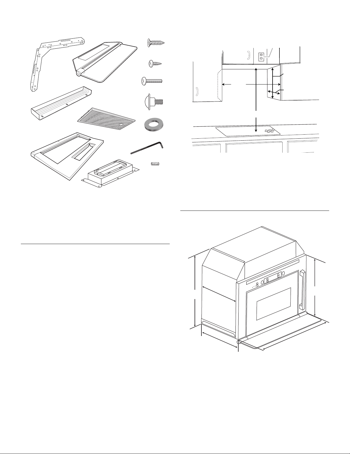
Parts Supplied
A
B
C
D
E
F
G
H
I
J
K
L
M
A
11¹⁵⁄₁₆" (30.3 cm) min.
13³⁄₄" (34.9 cm) max.
21" (53.3 cm) min.
21⁵⁄₈" (54.9 cm)**
39" (99.1 cm) min.
23
⁷⁄₈"
(60.6 cm) min.*
24
¹⁄₈"
(61.2 cm) max.*
23⁹⁄₁₆" (59.8 cm)
12⁵⁄₈" (32.0 cm)
20⁷⁄₁₆"
(51.9 cm)
16¹⁄₈"
(40.9 cm)
11¹³⁄₁₆" (30.0 cm)
For information on ordering, see “Replacement Parts” section.
A. L-brackets (2)
B. Rear trim
C. Bottom plate
D. Visor
E. Grease filter
F. Damper assembly
G. 16 mm wood screws (10)
H. 9.5 mm metal screws (10)
I. 16 mm round-head bolts (2)
J. 17 mm shoulder screws (2)
K. Washers (2)
L. Hex key
M. Leveling screws (4)
Installation Dimensions
NOTE: The grounded 3 prong outlet must be inside the upper
cabinet. See “Electrical Requirements” section.
A. Grounded 3 prong outlet
*Measure from the front edges of the side cabinets.
**For installation with stainless steel filler panel.
NOTE: To avoid stress on the power cord, a minimum of 1¹⁄₂"
(3.8 cm) must exist between the top surface of the microwave
oven’s upper component housing and the bottom of the upper
cabinet.
Product Dimensions
Location Requirements
Check the opening where the microwave oven will be installed.
The location must provide:
■ Minimum installation dimensions. See “Installation
Dimensions” illustration.
■ Side cabinets: Support for weight of 75 lbs (34 kg) each,
which includes microwave oven and items placed inside the
microwave oven and side cabinets.
■ Grounded electrical outlet inside upper cabinet. See
“Electrical Requirements” section.
NOTES:
■ Installation requires venting above the microwave oven.
■ Recirculation installation requires venting through a kitchen
soffit. See “Venting Requirements” section. A charcoal filter
kit should be used for recirculation. See “Assistance” section
for information on ordering.
■ If you are using a rectangular to round transition piece, 3"
(7.6 cm) clearance needs to exist above the damper
assembly so that the damper blade can open freely and fully.
See “Rectangular to Round Transition” illustration in “Venting
Requirements” section.
■ Some cabinet and building materials are not designed to
withstand the heat produced by the microwave oven for
cooking. Check with your builder or cabinet supplier to make
sure that the materials used will not discolor, delaminate or
sustain other damages.
3
Page 4
Electrical Requirements
Electrical Shock Hazard
Plug into a grounded 3 prong outlet.
Do not remove ground prong.
Do not use an adapter.
Do not use an extension cord.
Failure to follow these instructions can result in death,
fire, or electrical shock.
WARNING
GROUNDING INSTRUCTIONS
SAVE THESE INSTRUCTIONS
■
For all cord connected appliances:
The microwave oven must be grounded. In the event of
an electrical short circuit, grounding reduces the risk of
electric shock by providing an escape wire for the electric
current. The microwave oven is equipped with a cord
having a grounding wire with a grounding plug. The plug
must be plugged into an outlet that is properly installed
and grounded.
WARNING: Improper use of the grounding plug can
result in a risk of electric shock. Consult a qualified
electrician or serviceman if the grounding instructions are
not completely understood, or if doubt exists as to whether
the microwave oven is properly grounded.
Do not use an extension cord. If the power supply cord is
too short, have a qualified electrician or serviceman install
an outlet near the microwave oven.
Observe all governing codes and ordinances.
Required:
■ A 120 volt, 60 Hz, AC only, 15- or 20-amp electrical supply
with a fuse or circuit breaker.
Recommended:
■ A time-delay fuse or time-delay circuit breaker.
■ A separate circuit serving only this microwave oven.
Venting Requirements
This section is intended for architectural designer and
builder/contractor reference only.
NOTES:
■ If installing for recirculation, venting must be routed up and
out through an exhaust register (not provided) in a kitchen
soffit. A charcoal filter kit (not provided) should be used. See
“Assistance” section for information on ordering.
■ Vent materials needed for installation are not provided with
microwave hood combination.
■ We do not recommend using a flexible metal vent.
■ To avoid possible product damage, be sure to vent air
outside, unless using recirculation installation. Do not vent
exhaust air into concealed spaces, such as spaces within
walls or ceilings, attics, crawl spaces or garages.
For optimal venting installation, we recommend:
■ using roof or wall caps that have back draft dampers
■ using a rigid metal vent
■ using the most direct route by minimizing the length of the
vent and number of elbows to provide efficient performance
■ using uniformly sized vents
■ using duct tape to seal all joints in the vent system
■ using caulking compound to seal exterior wall or roof opening
around cap
■ for optimal hood performance, do not install 2 elbows
together
If rectangular to round transition is used, be sure there is at least
3" (7.6 cm) of clearance between the top of the damper assembly
and the transition piece. See “Rectangular to Round Transition”
illustration.
4
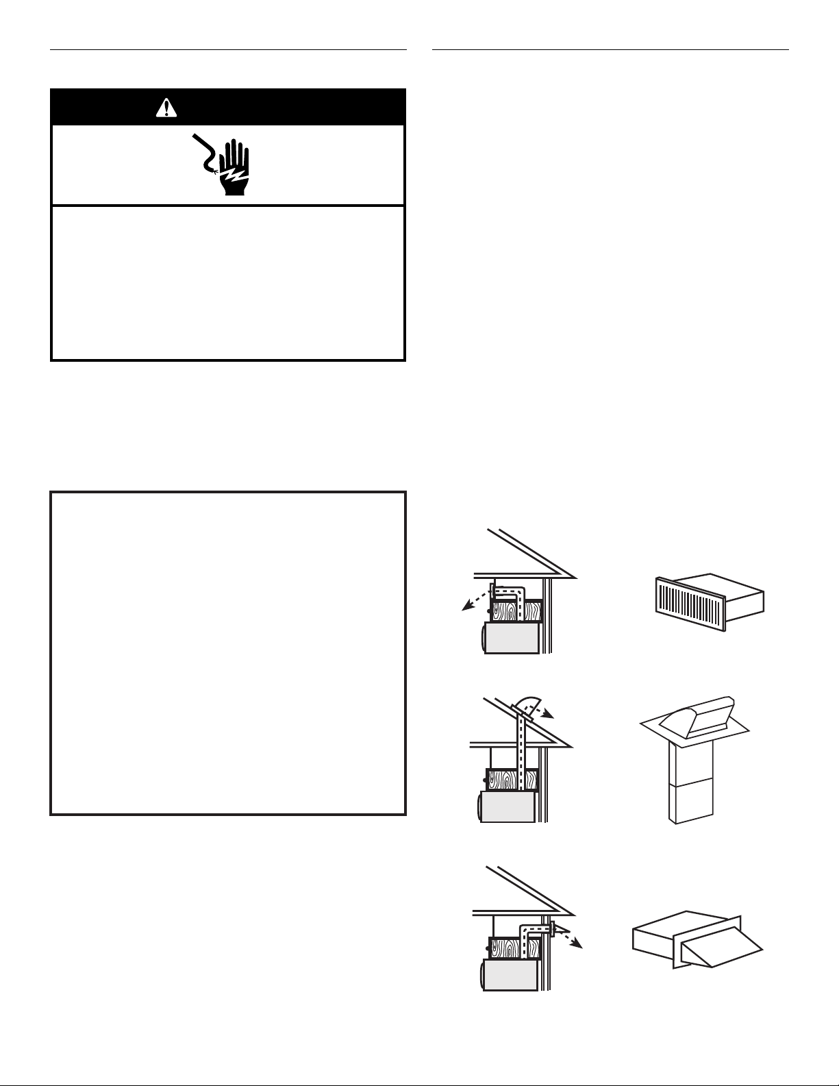
Recirculation venting Exhaust register
Roof venting Roof cap
Wall venting Wall cap
Page 5
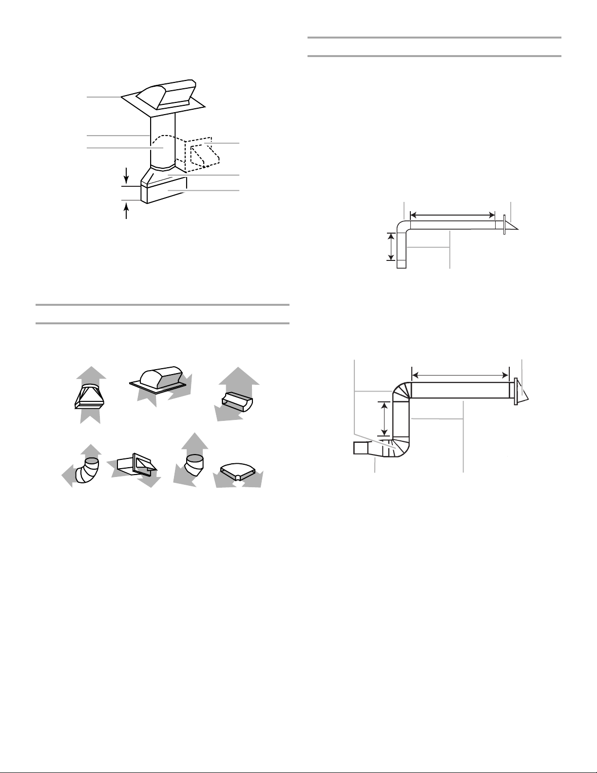
Rectangular to Round Transition
A
B
C
E
F
D
3" (7.6 cm)
A B C
D E F G
A B
C
6 ft (1.8 m)
2 ft
(0.6 m)
A B
C D
6 ft (1.8 m)
2 ft
(0.6 m)
NOTE: The minimum 3" (7.6 cm) clearance must exist between
the top of the damper assembly and the rectangular to round
transition piece so that the damper can open freely and fully.
A. Roof cap
B. 6" (15.2 cm) min. diameter round vent
C. Elbow (for wall venting only)
D. Wall cap
E. 3
¹⁄₄
" x 10" to 6" (8.3 x 25.4 cm to 15.2 cm)
rectangular to round transition piece
F. Vent extension piece, at least 3" (7.6 cm) high
Recommended Standard Fittings
Recommended Vent Length
A 3¹⁄₄" x 10" (8.3 x 25.4 cm) rectangular or 6" (15.2 cm) round vent
should be used.
The total length of the vent system including straight vent,
elbow(s), transitions and wall or roof caps must not exceed the
equivalent of 140 ft (42.7 m) for either type of vent. See
“Recommended Standard Fittings” section for equivalent lengths.
For best performance, use no more than three 90° elbows.
To calculate the length of the system you need, add the equivalent
lengths of each vent piece used in the system. See the following
examples:
3¹⁄₄" x 10" (8.3 x 25.4 cm) vent system = 73 ft (22.2 m) total
A. One 3
B. 1 wall cap = 40 ft (12.2 m)
C. 2 ft (0.6 m) + 6 ft (1.8 m) straight = 8 ft (2.4 m)
¹⁄₄
" x 10" (8.3 x 25.4 cm) 90° elbow = 25 ft (7.6 m)
The following length equivalents are for use when figuring vent
length. See the examples in “Recommended Vent Length.”
¹⁄₄
A. Rectangular to round transition piece: 3
(8.3 x 25.4 cm to 15.2 cm = 1.5 m)
B. Roof cap: 3
C. 90° elbow: 3
D. 90° elbow: 6" = 10 ft (15.2 cm = 3 m)
E. Wall cap: 3
F. 45° elbow: 6" = 5 ft (15.2 cm = 1.5 m)
G. 90° flat elbow: 3
¹⁄₄
" x 10" = 24 ft (8.3 x 25.4 cm = 7.3 m)
¹₄
" x 10" = 25 ft (8.3 x 25.4 cm = 7.6 m)
¹⁄₄
" x 10" = 40 ft (8.3 x 25.4 cm = 12.2 m)
¹⁄₄
" x 10" = 10 ft (8.3 x 25.4 cm = 3 m)
" x 10" to 6" = 5 ft
6" (15.2 cm) vent system = 73 ft (22.2 m) total
A. Two 90° elbows = 20 ft (6.1 m)
B. 1 wall cap = 40 ft (12.2 m)
C. 1 rectangular to round transition piece = 5 ft (1.5 m)
D. 2 ft (0.6 m) + 6 ft (1.8 m) straight = 8 ft (2.4 m)
If the existing vent is round, a rectangular to round transition piece
must be used. In addition, a rectangular 3" (7.6 cm) extension vent
between the damper assembly and rectangular to round transition
piece must be installed to keep the damper from sticking.
5
Page 6
INSTALLATION INSTRUCTIONS
18¹⁄₈" (46.0 cm) min.
A
B
C
¹¹⁄₁₆" (1.8 cm) min.
AB
CC
7" (17.8 cm) 7" (17.8 cm)
Rear wall
Centerline
Upper
cabinet
bottom
5" (12.7 cm)
2¹⁄₄"
(5.7 cm)
1
¹⁄₂" (3.8 cm)
diam.
A
B
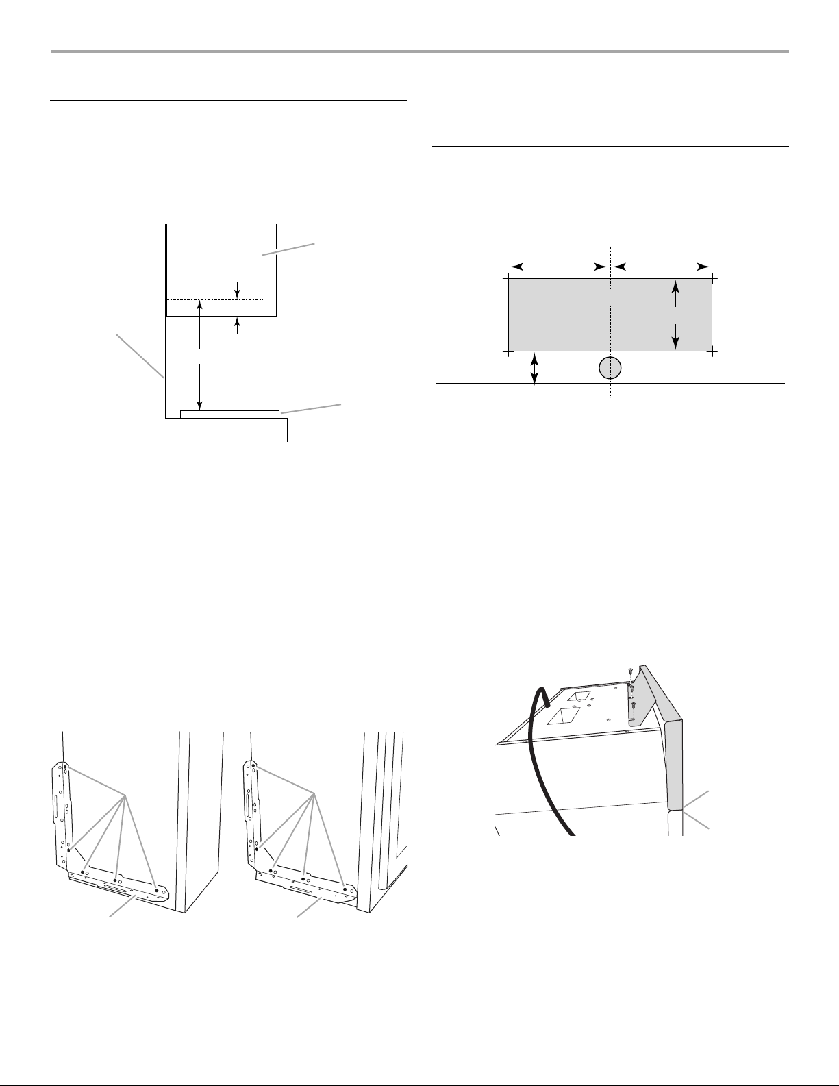
Install L-Brackets
1. Measure and mark a line on each of the side cabinets at least
18¹⁄₈" (46.0 cm) above the surface of the cooktop. See
“Installation Dimensions” in the “Location Requirements”
section.
Make sure each line is level front to back, and that the lines
are level to each other.
A. Rear wall
B. Side cabinet
C. Cooktop surface
2. Hold L-bracket against the side cabinet, with the bottom of
the horizontal arm aligning with the line drawn in Step 1, and
the vertical arm against the rear wall.
NOTES:
■ If installing into frameless or flush face-frame cabinetry (no
front face or protruding trim), position each bracket so that
the narrow arm is horizontal, and the wide arm is against
the rear wall.
■ If installing into face-frame cabinetry, position each
bracket so that the wide arm is horizontal, and the narrow
arm is against the rear wall.
3. Mark 3 holes through the horizontal arm onto the side cabinet,
then mark 2 holes through the vertical arm onto the side
cabinet, 1 at the top and 1 at the bottom.
Installation into frameless or
flush face-frame cabinetry
Installation into face-
frame cabinetry
4. Using 2 mm drill, drill holes marked in Step 3.
5. Secure L-brackets to side cabinets with ten 16 mm wood
screws, 5 in each L-bracket.
Prepare Upper Cabinet
1. Find the centerline of the installation space. Mark the
centerline on the bottom of the upper cabinet.
2. Measure and mark the power cord and vent holes, as shown,
making sure they are centered on the centerline.
3. Cut the power cord hole using the 1¹⁄₂" (3.8 cm) hole drill bit.
4. Cut 3/4" (19 mm) hole at one corner of the vent hole marking.
5. Using a keyhole saw, cut out the rectangular vent area.
Install Stainless Steel Panel Kit
(optional steps)
If you decide to cover the upper component housing with the
stainless steel panel (not provided), you will need to order the
stainless steel panel kit. See “Assistance” section for information
on ordering.
The panel must be attached to the microwave oven before
installation.
1. Peel off adhesive strip covers on bottom edge of panel, and
place the panel on the top edge of the front facing of the
microwave oven.
6
A. Narrow arm
B. Wide arm
C. Mounting holes
A. Bottom edge of stainless steel panel
B. Top edge of microwave oven front facing
2. Secure panel to upper component housing with 3 mounting
screws.
Page 7
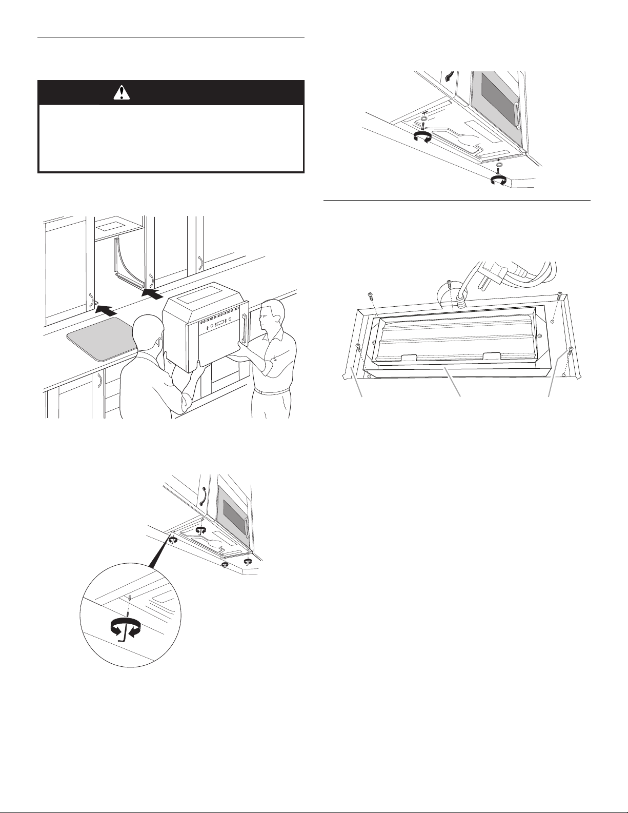
Install the Microwave Oven
WARNING
Excessive Weight Hazard
Use two or more people to move and install
microwave oven.
Failure to do so can result in back or other injury.
A B C
1. Remove any contents of the microwave oven.
2. Using 2 or more people, lift microwave oven, and place it onto
the L-brackets. Gently slide the microwave oven back against
the rear wall.
5. Place a washer on each 16 mm round-head bolt, then install
each bolt through the L-bracket base slot, into the mounting
hole in the bottom of the microwave oven. Do not overtighten.
Install Damper Assembly
1. Insert damper assembly through the upper cabinet cutout,
and orient it so that the 3 mounting holes are toward the back
of the microwave oven.
3. Check level of microwave oven.
4. Start the leveling screws in the front and back holes of the
L-bracket bases, and adjust the level using the hex key, if
necessary.
A. Damper assembly
B. Upper cabinet cutout
C. 9.5 mm metal screws (5)
2. Secure the damper assembly to the upper component
housing with five 9.5 mm metal screws.
7
Page 8
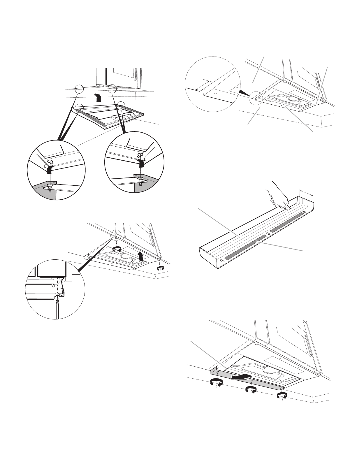
Install Bottom Plate
A
C
D
B
A
B
A
NOTE: Pre-tap front mounting holes prior to bottom plate
attachment. (See Step 2.)
1. Hook the heads of the screws through the keyholes at the
back of the microwave oven bottom, as shown, then slide
bottom plate back.
Install Rear Trim
1. Measure the distance from the rear wall to the front edge of
the rear frame of the bottom plate.
A. Left side cabinet bottom
B. Bottom plate
C. Rear frame of bottom plate
D. Rear wall
2. Cut the rear trim to the same measurement.
2. Secure bottom plate onto microwave oven bottom using two
9.5 mm metal screws through the front mounting holes
.
A. Rear trim
B. Adhesive cover
3. Peel off adhesive strip covers, and place the rear trim against
the rear wall and microwave oven bottom.
NOTE: Make sure trim does not cover the opening for grease
filter.
A. Opening for grease filter
4. Secure rear trim with three 9.5 mm metal screws.
8
Page 9
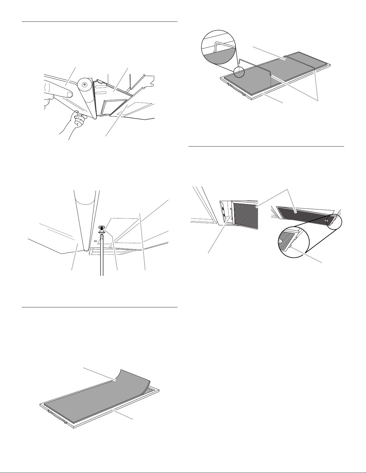
Install Visor
B
C
A
A B C
A
B
A
B
C
A
B
C
1. Open visor, and slide its mounting tray – with the mounting
tray edges facing down – into the slot between the microwave
oven bottom and the bottom plate, as shown.
2. Insert wire rods to hold charcoal filter in place.
A. Charcoal filter
B. Grease filter
C. Wire rods
3. Install grease filter. See “Install Grease Filter” section.
A. Visor
B. Visor mounting tray
C. Bottom plate
2. Secure visor by installing two 17 mm shoulder screws through
the bottom plate into the visor mounting tray.
A. Visor
B. 17 mm shoulder
C. Bottom plate
screws
Install Charcoal Filter Kit
(for recirculation venting only)
The charcoal filter kit should be used. See “Assistance” section
for information on ordering.
Install Grease Filter
1. Place bracket end of the grease filter into one side of the
bottom plate opening, push toward the bracket end, and
swing up the tabbed end of the grease filter.
A. Grease filter
B. Tabs
C. Bracket
2. Push the tabbed end of the grease filter up until the tabs are
above the opening, then release the tension.
To Install Charcoal Filter:
1. Cover the inside of the grease filter with the charcoal filter.
A. Charcoal filter
B. Grease filter
9
Page 10
Complete Installation
Electrical Shock Hazard
Plug into a grounded 3 prong outlet.
Do not remove ground prong.
Do not use an adapter.
Do not use an extension cord.
Failure to follow these instructions can result in death,
fire, or electrical shock.
WARNING
A
B
A
1. Connect all venting and ductwork necessary for the type of
installation (roof venting, wall venting or recirculation). See
“Venting Requirements” section.
2. Install turntable support and turntable.
3. Plug microwave oven into grounded 3 prong outlet.
4. Check the operation of microwave oven by placing 1 cup
(250 mL) of water on the turntable, and programming a cook
time of 1 minute at 100% power. Test vent fan and exhaust by
operating the vent fan.
5. If the microwave oven does not operate:
■ Check that a household fuse has not blown, or that a
circuit breaker has not tripped. Replace the fuse or reset
the circuit breaker. If the problem continues, call an
electrician.
■ Check that the power supply cord is plugged into a
grounded 3 prong outlet.
■ See the Use and Care Guide for troubleshooting
information.
Installation is now complete.
Save Installation Instructions for future use.
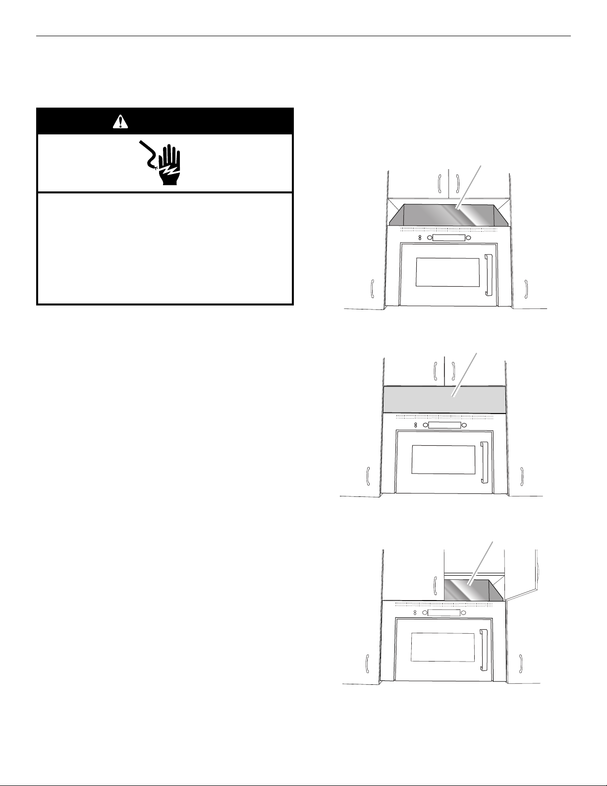
NOTE: After installation is complete, the upper component
housing on the top of the microwave oven will be visible (Figure 1).
The housing may be covered using a stainless steel panel kit
(Figure 1A). See “Assistance” section for information on ordering.
The housing may also be covered using cabinet customization
(Figure 1B). Check with your cabinet supplier/builder.
Figure 1
Figure 1A
10
Figure 1B
A. Upper component housing
B. Stainless steel panel
Page 11

ASSISTANCE
Call your authorized dealer or service center. When you call, you will need the microwave oven model number and serial number. Both
numbers can be found on the model and serial number plate, which is located behind the microwave oven door on the front frame of
the microwave oven.
If you need additional assistance, call us at our toll free number or visit our website listed in the Use and Care Guide.
Replacement Parts
If any of the installation hardware needs to be replaced, call us at
our toll free number listed in the Use and Care Guide.
Following is a list of available replacement parts. You will need
your model number located on the front facing of the microwave
oven opening, behind the door.
■ Damper Assembly
■ Visor
■ Rear Trim
■ Mounting Screw Kit (includes parts G-M in “Parts Supplied” in
the “Tools and Parts” section)
■ L-brackets
Kits
The following kits are not provided but may be ordered.
■ Charcoal Filter Kit (Part Number W10610033) Includes:
1 charcoal filter
2 wire rods
■ Stainless Steel Panel Kit (Part Number W11170104) Includes:
1 stainless steel panel
3 mounting screws
1 Installation Instruction
11
Page 12

W11174207A
©2017. Used under license in Canada. All rights reserved.
Utilisé sous licence au Canada. Tous droits réservés.
12/17
Printed in Italy
Imprimé en Italie
 Loading...