

Whirlpool SF388PEWN0 User Manual
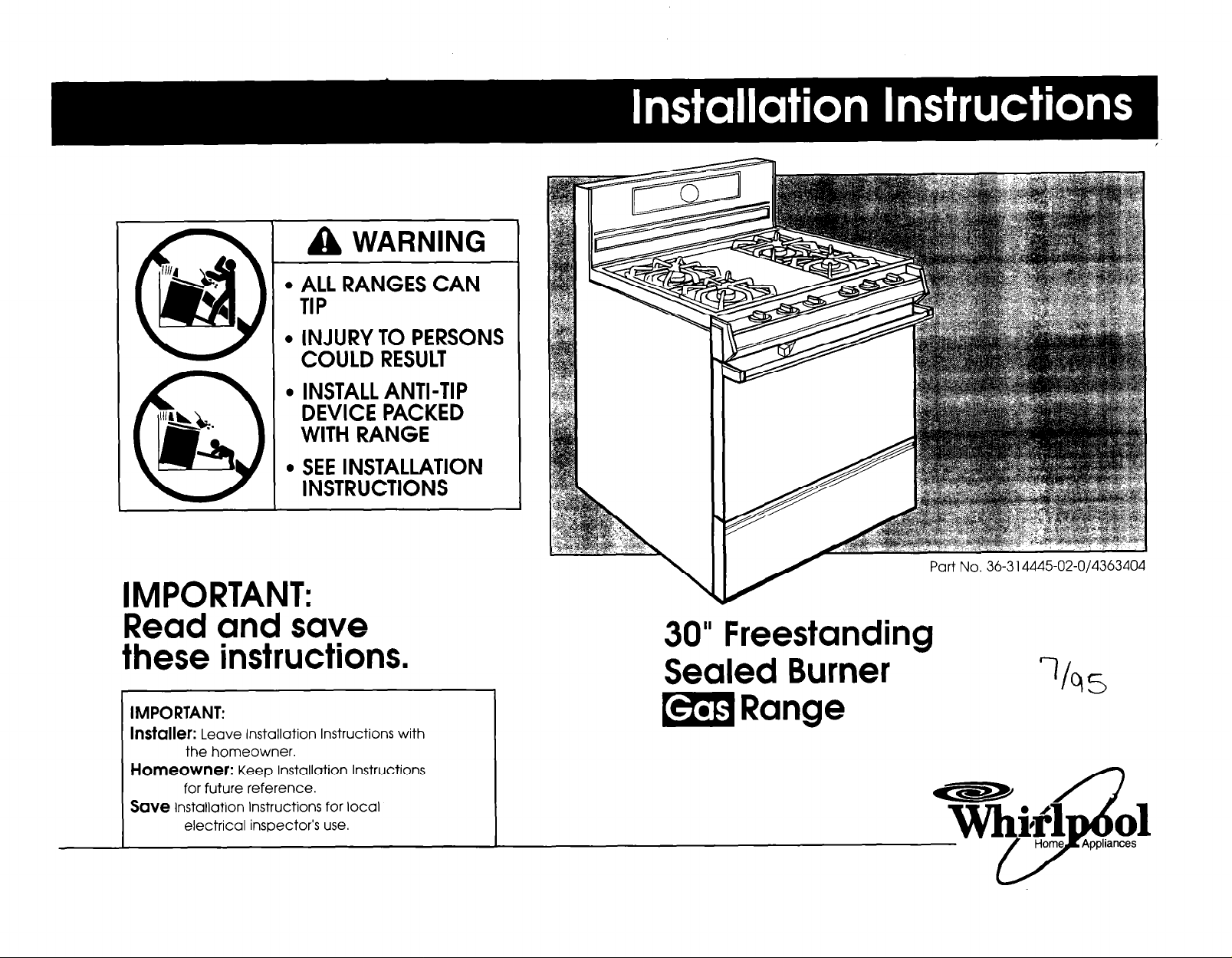
] A WARNING
. ALL RANGES CAN
TIP
. INJURY TO PERSONS
COULD RESULT
. INSTALL ANTI-TIP
DEVICE PACKED
WITH RANGE
. SEE INSTALLATION
INSTRUCTIONS
IMPORTANT:
Part No. 36-3 14445-02-O/4363404
Read and save
these instructions.
IMPORTANT:
IIlStdkr: Leave Installation Instructions with
the homeowner.
Homeowner:
for future reference.
Save
Installation Instructions for local
electrical inspector’s use.
Keep Installation Instructions
30” Freestanding
Sealed Burner
m Range
Before you start...
Proper installation; your responsibility. A qualified
technician should install this range. Make sure you
have everything necessary for correct installation. It is
the responsibility of the installer to comply with the
installation clearances specified on the serial/rating
plate. The serial/rating plate is located on the oven
frame behind the oven door.
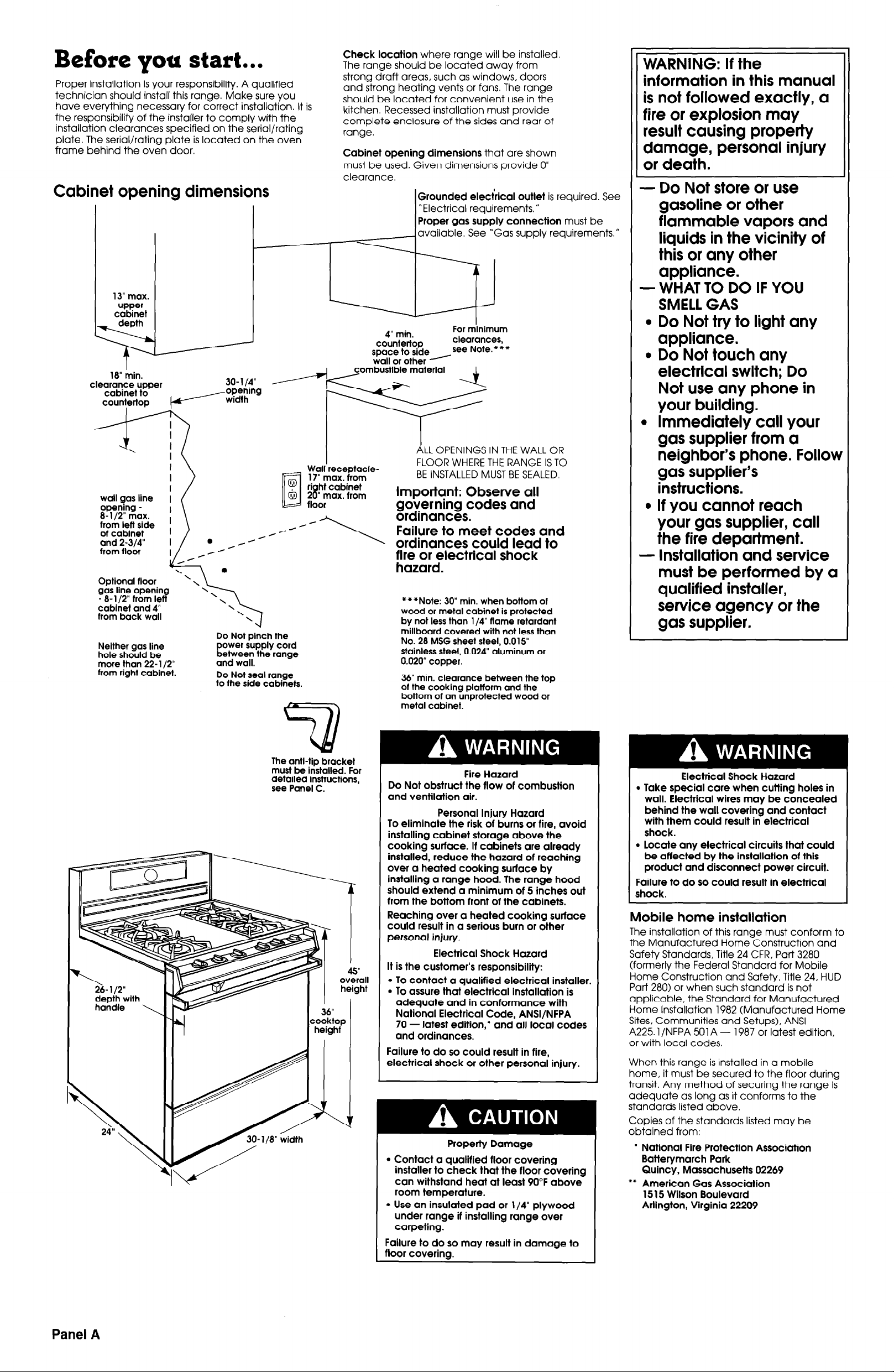
Cabinet opening dimensions
13” max.
upper
cabinet
. 16” min.
clearance upper
cabinet to
countertop
7 17” max. from
wall gas line
opening 8- l/2” max.
from left side
of cabinet
and 2-314”
from floor
Optional floor
gas line opening
- 8- l/2” from left
cabinef and 4”
from back wall
Neither gas line
hole should be
more than 22-l/2”
from right cabinet.
\
\
\
\
\
\
Do
power supply cord
between the range
and wall.
Do Not seal range
fo fhe side cabinets.
\
\
\
Not pinch the
Check location
The range should be located away from
strong draft areas, such as windows, doors
and strong heating vents or fans. The range
should be located for convenient use in the
kitchen. Recessed installation must provide
complete enclosure of the sides and rear of
range.
Cabinet opening dimensions
must be used. Given dimensions provide 0”
clearance.
I
I
Wall receptacle-
where range will be installed
that are shown
IGrounded electrical outlet
1 “Electrical requirements.”
Proper gas supply connection
available. See ‘Gas supply requirements.”
4” min.
countertop
space to sideySee Nofe.*’
wall or other
ALL OPENINGS IN THE WALL OR
FLOOR WHERE THE RANGE IS TO
BE INSTALLED MUST BE SEALED.
For minimur
clearance -
Important: Observe all
tirirz;;zlectrical shock
.
***Note: 30” min. when bottom of
wood or metal cabinet is protected
by not less than l/4” flame retardant
millboard covered with not less than
No. 28 MSG sheet steel, 0.015”
stainless steel, 0.024” aluminum or
0.020” copper.
36” min. clearance between the top
of the cooking platform and the
bottom of an unprotected wood or
metal cabinet.
is required. See
must be
WARNING: If the
information in this manual
is not followed exactly, a
fire or explosion may
result causing property
damage, personal injury
or death.
- Do Not store or use
gasoline or other
flammable vapors and
liquids in the vicinity of
this or any other
appliance.
- WHAT TO DO IF YOU
SMELL GAS
l
Do Not try to light any
appliance.
l
Do Not touch any
electrical switch; Do
Not use any phone in
your building.
l
Immediately call your
gas supplier from a
neighbor’s phone. Follow
gas supplier’s
instructions.
l
If you cannot reach
your gas supplier, call
the fire department.
- Installation and service
must be performed by a
qualified installer,
service agency or the
gas supplier.
L
J
depth with
handle \
The anti-tip bracket
must be installed. For
detailed instructions,
see Panel C.
cooktop
heighf
Fire Hazard
Do Not obstruct the flow of combustion
and ventilation air.
Personal Injury Hazard
To eliminate the risk of burns or fire, avoid
installing cabinet storage above the
cooking surface. If cabinets are already
installed, reduce the hazard of reaching
over a heated cooking surface by
installing a range hood. The range hood
should extend a minimum of 5 inches out
from the bottom front of the cabinets.
Reaching over a heated cooking surface
could result in a serious burn or other
personal injury.
Electrical Shock Hazard
It is the customer’s responsibility:
l
To contact a qualified electrical installer.
. To assure that electrical installation is
adequate and in conformance with
National Electrical Code, ANSI/NFPA
70 - latest edition,* and all local codes
and ordinances.
Failure to do so could result in fire,
electrical shock or other personal injury.
L
Property Damage
l
Contact a qualified floor covering
installer to check that the floor covering
can withstand heat at least 90°F above
room temperature.
l
Use an insulated pad or l/4” plywood
under range if installing range over
carpeting.
Failure to do so may result in damage to
floor coverina.
Electrical Shock Hazard
l
Take special care when cutting holes in
wall. Electrical wires may be concealed
behind the wall covering and contact
with them could result in electrical
shock.
l
Locate any electrical circuits that could
be affected by the installation of this
product and disconnect power circuit.
Failure to do so could result in electrical
shock.
Mobile home installation
The installation of this range must conform to
the Manufactured Home Construction and
Safety Standards, Title 24 CFR. Part 3280
(formerly the Federal Standard for Mobile
Home Construction and Safety, Title 24, HUD
Part 280) or when such standard is not
applicable, the Standard for Manufactured
Home Installation 1982 (Manufactured Home
Sites, Communities and Setups), ANSI
A225.1 /NFPA 501 A - 1987 or latest edition,
or with local codes.
When this range is installed in a mobile
home, it must be secured to the floor during
transit. Any method of securing the range is
adequate as long as it conforms to the
standards listed above.
Copies of the standards listed may be
obtained from:
l
National Fire Protection Association
Batterymarch Park
Quincy, Massachusetts 02269
l
* American Gas Association
15 15 Wilson Boulevard
Arlington, Virginia 22209
Panel
A
Tools needed for
shutoff valve
Recommended
installation:
l
hand or electric drill
concrete/ceramic floors: Q/16” masonry drill bit
wood floors: 3/32” drill bit
l
gas line shutoff valve
l
L.P.-resistant pipe-joint compound
l
A.G.A. design-certified flexible metal connector
(A-5 feet)
wrench V
‘V
c
Gas supply requirements
I
r
n
The supply line shall be equipped with
an approved shutoff valve. This valve should
be located in the same room as the range
and should be in a location that allows ease
of opening and closing. Do Not block
access to shutoff valve.
supply
pipe fittings must
obtain an in-line
range. All strains must be removed from the
supply and fuel lines so range will be level
and in line.
line, a corn
H
n
should be as follows for both operation and
checking regulator setting:
NATURAL GAS:
Set pressure 5 inches
Maximum inlet pressure 14 inches
L.P. GAS:
Set pressure 11 inches
Maximum inlet pressure 14 inches
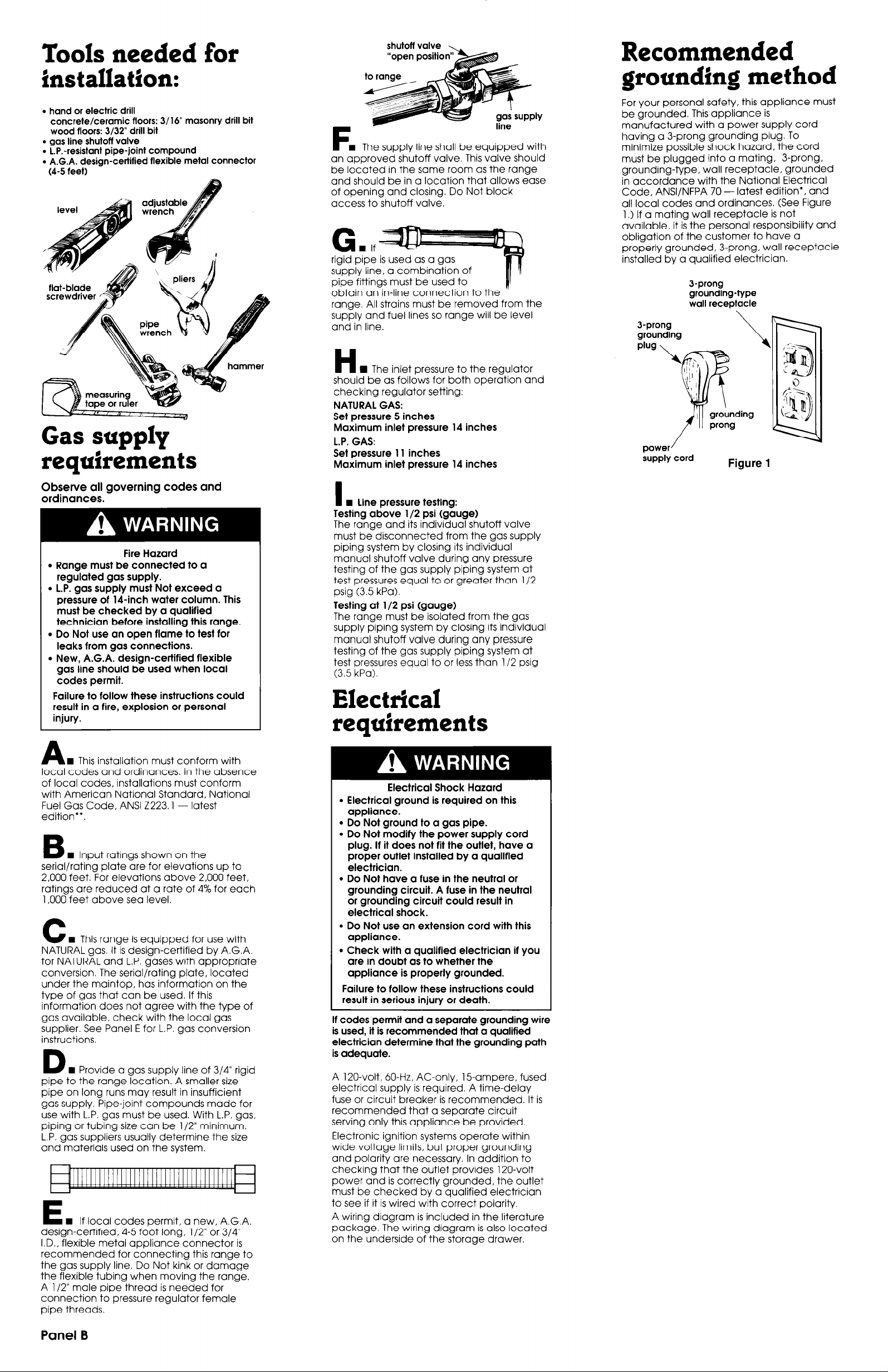
The inlet pressure to the regulator
grounding method
For your personal safety, this appliance must
be grounded. This appliance is
manufactured with a power supply cord
having a 3-prong grounding plug. To
minimize possible shock hazard, the cord
must be plugged into a mating, 3-prong,
grounding-type, wall receptacle, grounded
in accordance with the National Electrical
Code, ANSVNFPA 70 - latest edition*, and
all local codes and ordinances. (See Figure
1.) If a mating wall receptacle is not
available, it is the personal responsibility and
obligation of the customer to have a
properly grounded, 3-prong, wall receptacle
installed by a qualified electrician.
J-prong
grounding-type
wall receptacle
J-prong
grounding
plug
/
power
supply cord
Figure 1
Observe all governing codes and
ordinances.
Fire Hazard
l
Range must be connected to a
regulated gas supply.
. L.P. gas supply must Not exceed a
pressure of 14-inch water column. This
must be checked by a qualified
technician before installing this range.
l
Do Not use an open flame to test for
leaks from gas connections.
l
New, A.G.A. design-certified flexible
gas line should be used when local
codes permit.
Failure to follow these instructions could
result in a fire, explosion or personal
injury.
n
A
local codes and ordinances. In the absence
of local codes, installations must conform
with American National Standard, National
Fuel Gas Code, ANSI 2223.1 - latest
edition**.
B
serial/rating plate are for elevations up to
2,000 feet. For elevations above 2,000 feet,
ratings are reduced at a rate of 4% for each
1,000 feet above sea level.
C
NATURAL gas It is design-certified by A.G.A.
for NATURAL and L.P. gases with appropriate
conversion. The serial/rating plate, located
under the maintop, has information on the
type of gas that can be used. If this
information does not agree with the type of
gas available, check with the local gas
supplier. See Panel E for L.P. gas conversion
instructions.
D
pipe to the range location. A smaller size pipe on long runs may result in insufficient
gas supply. Pipe-joint compounds made for
use with L.P. gas must be used. With L.P. gas,
piping or tubing size can be l/2” minimum.
L.P. gas suppliers usually determine the size
and materials used on the system.
E
design-certified, 4-5 foot long, l/2” or 314”
I.D., flexible metal appliance connector is
recommended for connecting this range to
the gas supply line. Do Not kink or damage
the flexible tubing when moving the range.
A l/2” male pipe thread is needed for
connection to pressure regulator female
pipe threads.
This installation must conform with
n
Input ratinas shown on the
n
This range is equipped for use with
n
Provide a gas supply line of 3/4” rigid
n
If local codes permit, a new, A.G.A.
I W Line pressure testing:
Testing above l/2 psi (gauge)
The range and its individual shutoff valve
must be disconnected from the gas supply
piping system by closing its individual
manual shutoff valve during any pressure
testing of the gas supply piping system at
test pressures equal to or greater than l/2
psig (3.5 kPa).
Testing at l/2 psi (gauge)
The range must be isolated from the gas
supply piping system by closing its individual
manual shutoff valve during any pressure
testing of the gas supply piping system at
test pressures equal to or less than l/2 psig
(3.5 kPa).
Electrical requirements
Electrical Shock Hazard
l
Electrical ground is required on this
appliance.
l
Do Not ground to a gas pipe.
l
Do Not modify the power supply cord
plug. If it does not fit the outlet, have a
proper outlet installed by a qualified
electrician.
l
Do Not have a fuse in the neutral or
grounding circuit. A fuse in the neutral
or grounding circuit could result in
electrical shock.
l
Do Not use an extension cord with this
appliance.
l
Check with a qualified electrician if you
are in doubt as to whether the
appliance is properly grounded.
Failure to follow these instructions could
result in serious injury or death.
If codes permit and a separate grounding wire
is used, it is recommended that a qualified
electrician determine that the grounding path
is adequate.
A 120-volt, 60-Hz, AC-only, 15.ampere, fused
electrical supply is required. A time-delay
fuse or circuit breaker is recommended. It is
recommended that a separate circuit
serving only this appliance be provided.
Electronic ignition systems operate within
wide voltage limits, but proper grounding
and polarity are necessary. In addition to
checking that the outlet provides 120-volt
power and is correctly grounded, the outlet
must be checked by a qualified electrician
to see if it is wired with correct polarity
A wiring diagram is included in the literature
package. The wiring diagram is also located
on the underside of the storage drawer.
Panel B
 Loading...