

Whirlpool RHH 2300 User Manual
INSTALLATION
and
OPERATING INSTRUCTIONS
f
or
~irlpool VENTED RANGE HOOD RHH 2300SERlES
TO INSTALL RANGE HOOD
For most efficient operation, the top of the hood should be
approximately 66 inches (137.6 cm) from the floor. See
Figure 5 for examples of two typical ductwork
installations. Choose the best method for your
installation.
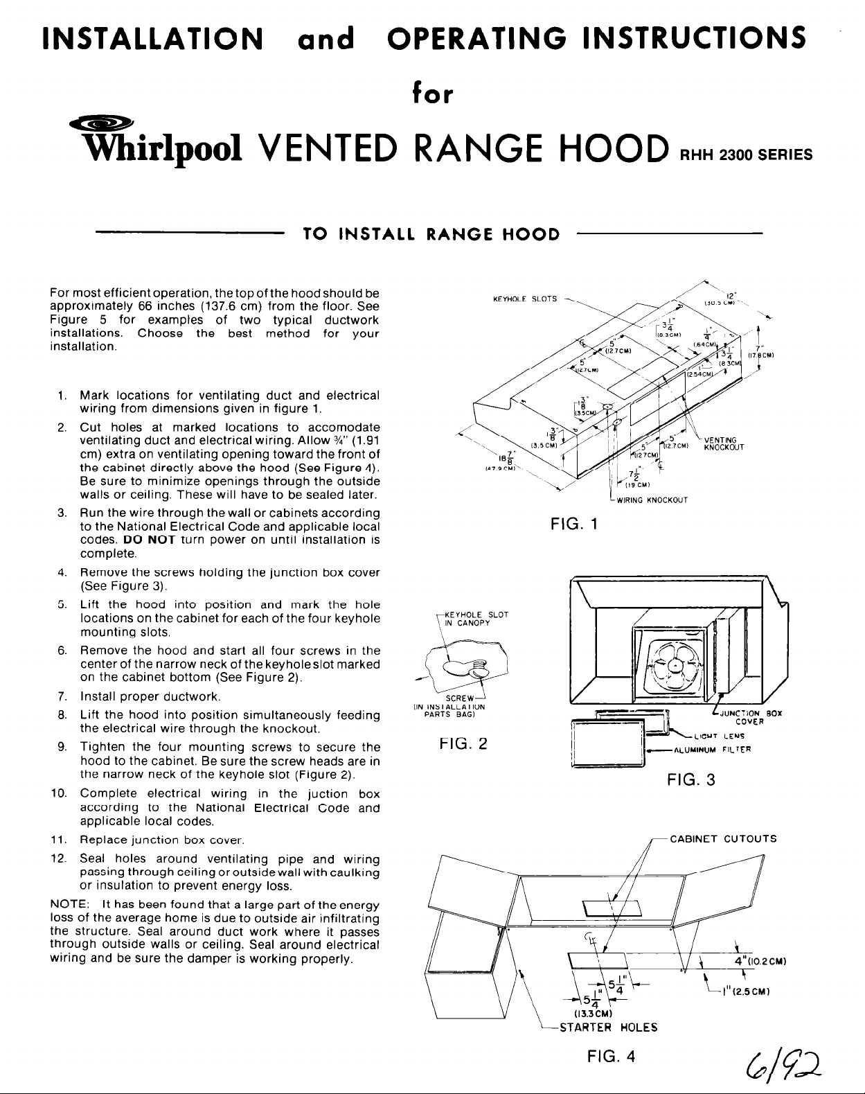
Mark locations for ventilating duct and electrical
1.
wiring from dimensions given in figure 1.
Cut holes at marked locations to accomodate
2.
ventilating duct and electrical wiring. Allow %” (1.91
cm) extra on ventilating opening toward the front of
the cabinet directly above the hood (See Figure 4).
Be sure to minimize openings through the outside
walls or ceiling. These will have to be sealed later.
3.
Run the wire through the wall or cabinets according
to the National Electrical Code and applicable local
codes. DO NOT turn power on until installation is
complete.
4.
Remove the screws holding the junction box cover
(See Figure 3).
5.
Lift the hood into position and mark the hole
locations on the cabinet for each of the four keyhole
mounting slots.
Remove the hood and start all four screws in the
6.
center of the narrow neck of the keyholeslot marked
on the cabinet bottom (See Figure 2).
7.
Install proper ductwork.
Lift the hood into position simultaneously feeding
8.
the electrical wire through the knockout.
9.
Tighten the four mounting screws to secure the
hood to the cabinet. Be sure the screw heads are in
the narrow neck of the keyhole slot (Figure 2).
10.
Complete electrical wiring in the juction box
according to the National Electrical Code and
applicable local codes,
11.
Replace junction box cover.
12.
Seal holes around ventilating pipe and wiring
passing through ceiling oroutsidewall with caulking
or insulation to prevent energy loss.
NOTE:
loss of the average home is due to outside air infiltrating
the structure. Seal around duct work where it passes
through outside walls or ceiling. Seal around electrical
wiring and be sure the damper is working properly.
It has been found that a large part of the energy
KEYHOLE SLOT
IN CANOPY
IIN INSTALLATION
PARTS BAG1
FIG. 2
KEYHOLE SLOTS
FIG. 1
--i
L
WIRING KNOCKOUT
FIG. 3
/-CABINET CUTOUTS
LJUNCTION BOX
COVER
STARTER HOLES
OPERATION AND CARE OF UNIT
CARE OF FILTERS:
ALUMINUM FILTER: For greater efficiency, the
permanent type aluminum filter should be removed and
cleaned periodically.
To clean, the filter should be soaked in hot water and
detergent, and thoroughly rinsed. The aluminum filter can
be cleaned in a dishwasher.
LIGHTS:
Do not use bulb larger than 60 watts in light socket.
CARE OF FAN MOTOR:
Fan motor has life time sealed bearings that never need
oiling under normal usage. A few drops on each bearing
after three years of heavy usage will prolong the motor
life. Clean motor with a damp cloth and grease cutting
detergent when a heavy coating of grease has
accumulated.
CARE OF EXTERIOR SURFACES:
Your range hood is a beautifully finished addition to your
kitchen and requires only the care you give your range to
preserve its lasting beauty. Clean with a mild detergent to
preserve finish. DO NOT use abrasive cleaners.
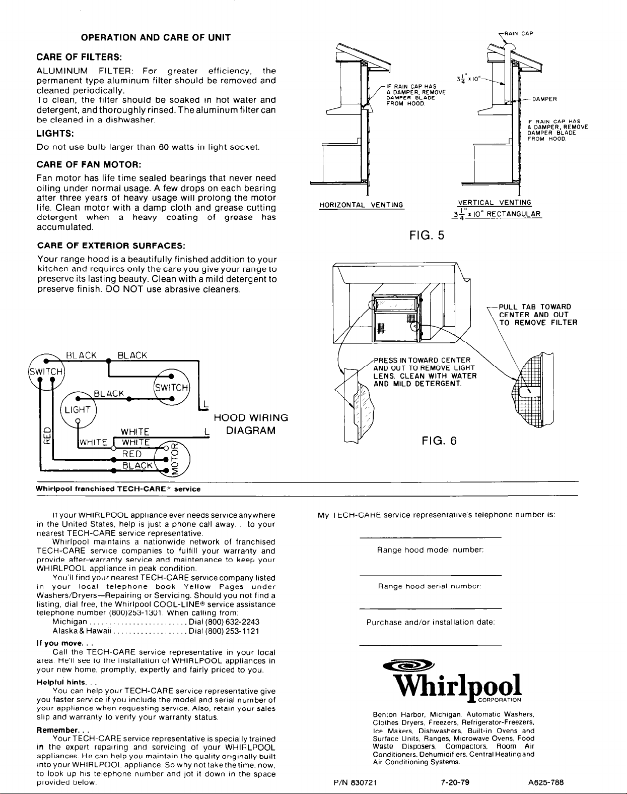
IF RAIN CAP HAS
A DAMPER. REMOVE
DAMPER BLADE
FROM HOOD.
HORIZONTAL VENTING
FIG. 5
TRAIN CAP
IF RAIN CAP HAS
A DAMPER, REMOVE
DAMPER BLADE
FROM HOOD.
VERTICAL VENTING
.,
II
&‘x IO RECTANGULAR
ULL TAB TOWARD
ENTER AND OUT
0 REMOVE FILTER
,,,--., BLACK _ BLACK
I
HOOD WIRING
DIAGRAM
Whirlpool franchised TECH-CARE” service
If your WHIRLPOOL appliance ever needs serviceanywhere
in the United States, help is just a phone call away. .to your
nearest TECH-CARE service representative.
Whtrlpool malntalns a nationwide network of franchised
TECH-CARE service companies to fulfill your warranty and
provide after-warranty service and maintenance to keep your
WHIRLPOOL appliance in peak condition.
You’ll find your nearest TECH-CARE servlcecompany listed
in your local telephone book Yellow Pages under
Washers/Dryers-Repairing or Servicing. Should you not find a
listing. dial free, the Whirlpool COOL-LINE@ service assistance
telephone number (800)253-1301. When calling from:
Michigan Dial (800) 632-2243
Alaska& Hawall Dial (800) 253-l 121
If you move.
Call the TECH-CARE service representative in your local
area He’ll see to the installation of WHIRLPOOL appliances in
your new home, promptly, expertly and fairly priced to you.
Helpful hints. .
You can help your TECH-CARE service representative give
you faster service if you include the model and serial number of
your appliance when requesting service. Also, retain your sales
slop and warranty to verify your warranty status.
Remember..
Your TECH-CARE service representative is specially trained
In the expert repairing and servicing of your WHIRLPOOL
appliances He can help you maintain the quality orIgInally built
mto your WHIRLPOOIL appliance. So why not take thelime. now,
to look up his telephone number and jot it down In the space
provided below.
RESS IN TOWARD CE
ND OUT TO REMOVE
ENS. CLEAN WITH
ND MILD DETERGE
My TECH-CARE service representative’s telephone number
Range hood model number:
Range hood senal number:
Purchase and/or installation date:
P/N 830721
Tklpool
Benton Harbor, Mlchlgan Automatic Washers,
Clothes Dryers, Freezers, Relngerator-Freezers.
Ice Makers, DIshwashers, Built-in Ovens and
Surface Umts, Ranges, MIcrowave Ovens, Food
Waste Disposers, Compactors. Room Air
Conditioners. Dehumldlflers. Central Heating and
Air Conditioning Systems.
7-20-79 A625788
CORPORATlON
IS:
 Loading...