

Whirlpool RH8930XLS User Manual
VENTED KITCHEN RANGE HOOD
FOR 120 V. OPERATION
READ AND SAVE THESE INSTRUCTIONS
Before you begin, read the following instructions
completely and carefully. If followed, they will simplify
the installation job.
IMPORTANT: OBSERVE ALL GOVERNING CODES
AND ORDINANCES
SAVE THESE INSTRUCTIONS FOR THE LOCAL
I
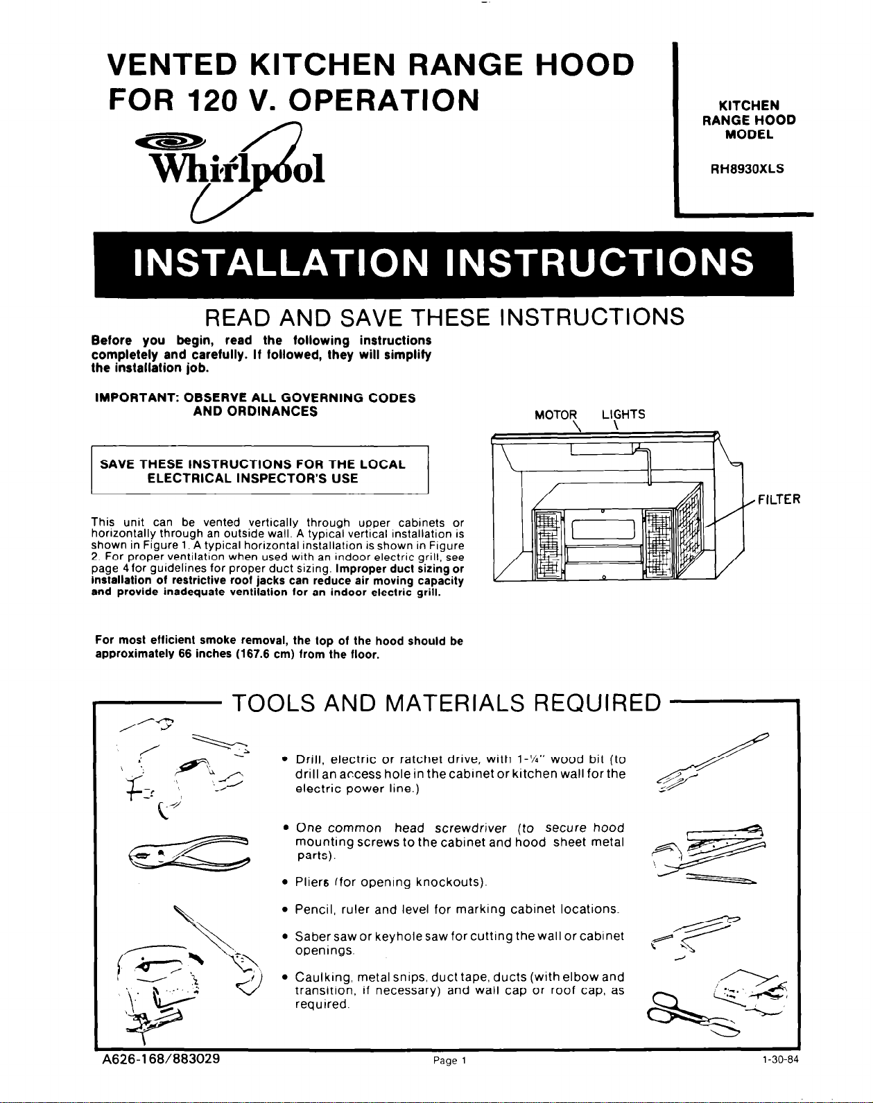
This unit can be vented vertically through upper cabinets or
horlzontally through an outside wall. A typical vertical installation is
shown in Figure 1. A typical horizontal installation is shown in Figure
2. For proper ventilation when used with an indoor electric grill, see
page 4for guidelines for proper duct sizing. Improper duct sizing or
lnsfallation of restrictive roof jacks can reduce air
and provide inadequate ventilation ior an indoor electric
ELECTRICAL INSPECTOR’S USE
moving
capacity
grill.
MOTOR
KITCHEN
RANGE HOOD
MODEL
RH8930XLS
LIGHTS
FILTER
For most
approximately 66 inches (167.6 cm) from the floor.
eflicient smoke removal, the top of the hood should be
TOOLS AND MATERIALS REQUIRED
/-T
/
;
1
J FL;
T
I+
bl
‘,-/
l
Drill, electric or ratchet drive, with l-‘/4” wood bit (to
drill
an access hole in the cabinet or kitchen wall for the
electric power line.)
l
One common head screwdriver (to secure hood
mounting screws to the cabinet and hood sheet metal
parts).
l
Pliers ffor opening knockouts).
l
Pencil, ruler and level for marking cabinet locations.
l
Saber saw or keyhole saw for cutting the wall or cabinet
openings.
l
Caulking, metal snips, duct tape, ducts (with elbow and
transitron. if necessary) and wall cap or roof cap, as
required.
/
29
A626-168/883029
Page
1
l-30-84
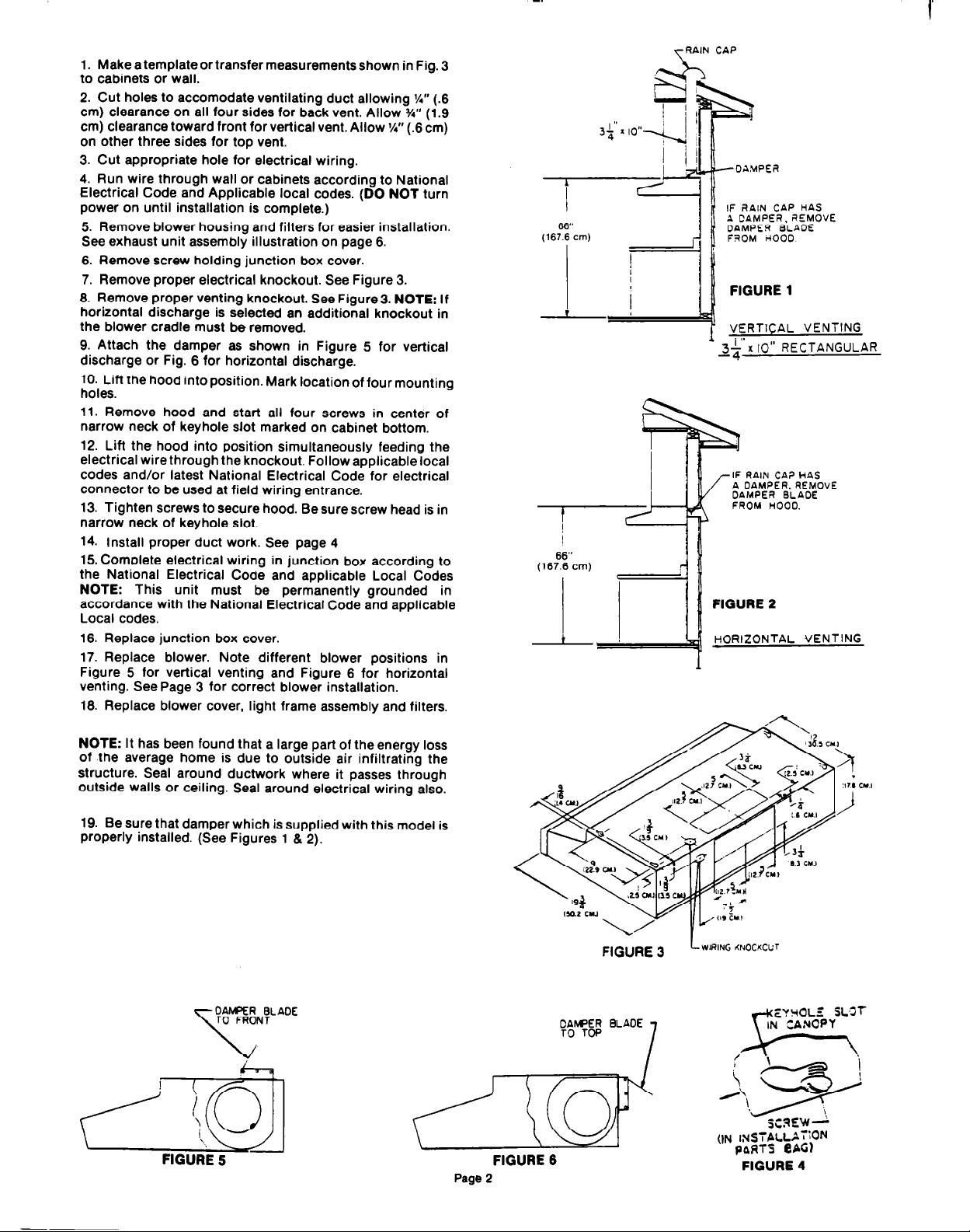
Make a template or transfer measurements shown in Fig. 3
1.
to cabinets or wall.
2. Cut holes to accomodate ventilating duct allowing W’ (.6
cm) clearance on all four sides for back vent. Allow J/4” (1.9
cm) clearance toward front for vertical vent. Allow %” (.6 cm)
on other three sides for top vent.
3. Cut appropriate hole for electrical wiring.
4. Run wire through wall or cabinets according to National
Electrical Code and Applicable local codes. (DO NOT turn
power on until installation is complete.)
5. Remove blower housing and filters for easier installation.
See exhaust unit assembly illustration on page 6.
6. Remove screw holding junction box cover.
7. Remove proper electrical knockout. See Figure 3.
8. Remove proper venting knockout. See Figure3. NOTE: If
horizontal discharge is selected an additional knockout in
the blower cradle must be removed.
9. Attach the damper as shown in Figure 5 for vertical
discharge or Fig. 6 for horizontal discharge.
10. Lift the hood into position. Mark location of four mounting
holes.
11. Remove hood and start all four screws in center of
narrow neck of keyhole slot marked on cabinet bottom.
12. Lift the hood into position simultaneously feeding the
electrical wire through the knockout. Follow applicable local
codes and/or latest National Electrical Code for electrical
connector to be used at field wiring entrance.
13. Tighten screws to secure hood. Be sure screw head is in
narrow neck of keyhole slot.
14. Install proper duct work. See page 4
15. Complete electrical wiring in junction box according to
the National Electrical Code and applicable Local Codes
NOTE: This unit must be permanently grounded in
accordance with the National Electrical Code and applicable
Local codes.
16. Replace junction box cover.
17. Replace blower. Note different blower positions in
Figure 5 for vertical venting and Figure 6 for horizontal
venting. See Page 3 for correct blower installation.
18. Replace blower cover, light frame assembly and filters.
TRAIN CAP
IF RAIN CAP HAS
A CAMPER, REMOVE
DAMPEF) BLADE
FROM rCOO0
FIGURE 1
VERTICAL VENTING
,a
3%. x IO” RECTANGULAR
IF RAIN CAP HAS
A DAMPER. REMOVE
DAMPER BLAOE
FROM HOOD.
FIGURE 2
HORIZONTAL VENTING
NOTE: It has been found that a large part of the energy loss
of the average home is due to outside air infiltrating the
structure. Seal around ductwork where it passes through
outside walls or ceiling. Seal around electrical wiring also.
Be sure that damper which is supplied with this model is
19.
properly installed. (See Figures 1 8 2).
6-1
c5mf
FIG&E 5
Page 2
FIGURE 6
FIGURE 4
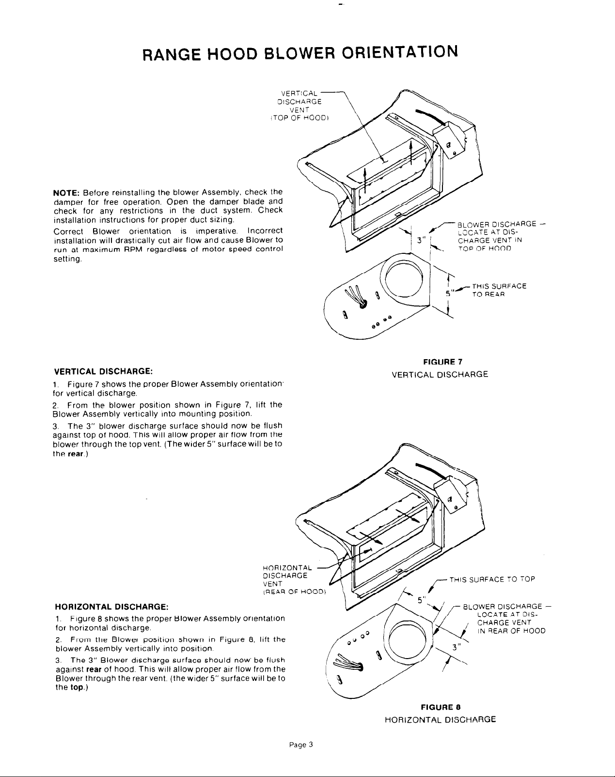
RANGE HOOD BLOWER ORIENTATION
(TOP OF HOOD1
NOTE:
damper for free operation. Open the damper blade and
check for any restrictions in the duct system. Check
installation instructions for proper duct sizing.
Correct Blower orientation is imperative. Incorrect
tnstallatron will drastically cut atr flow and cause Blower to
run at maximum RPM regardless of motor speed control
setting.
Before reinstalling the blower Assembly, check the
VERTICAL DISCHARGE:
1, Figure 7 shows the proper Blower Assembly ortentatton’
for vertical discharge.
2. From the blower position shown in Figure 7. lift the
Blower Assembly verttcally Into mounting position.
3. The 3” blower drscharge surface should now be flush
against top of hood. This will allow proper air flow from the
blower through the top vent. (The wider 5” surface will be to
the rear.)
BLOWER DISCHARGE ‘LXATE AT OIS-
CHARGE VENT IN
TOP OF HOOD
,,/ THIS SURFACE
TO REAR
FIGURE 7
VERTtCAL DISCHARGE
HORIZONTAL
DISCHARGE
VENT
(REAR OF HOOD)
HORIZONTAL DISCHARGE:
1. Figure 8 shows the proper Blower Assembly orientation
for horizontal discharge.
2. From the Blower position shown in Figure 8. lift the
blower Assembly vertrcally into position
3. The 3” Blower drscharge surface should now’ be flush
against rear of hood. This
Blower through the rear vent. (the wider 5” surface will be to
the top.)
will
allow proper air flow from the
Page 3
THIS
SURFACE TO TOI=
BLOWER DISCHARGE -
LOCATE AT DIS-
FIGURE 8
HORIZONTAL DISCHARGE
 Loading...