

Whirlpool RGH 8300-1, RGH 8300-2 User Manual
TO INSTALL RANGE HOOD
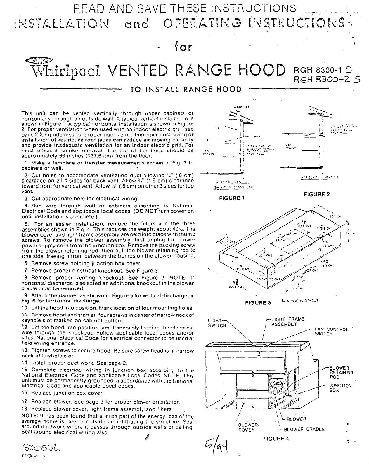
This unit can be vented vertically through uoper cabine!s or
horrzontally through an outside wall. A typical vertical installet~on iS
shown in Figure 1. A ryolcal horizonial rnstallatron IS shown In Figure
2. For proper ventila:ron when used wrth an indoor electrrc grill. see
paoe 2 for gurctelines for proper auct sizing. Improper duct sizing or
ins:alletion of restrictive roof jacks can reduce air moving capacity
and provide inadequate ventilation for an indoor electric grill. For
mcst efficient smoke removal, the top of the hood should be
approximately 56 Inches (13T.6 cm) from the floor.
1. Make a template or transfer measurements shown in Fig. 3 to
cabinets or wall.
2. Cut holes to accomodate ventilating duct allowing ‘4” (-6 cm)
clearance on all 4 srdes for back vent. Allow !.” (1.9 cm) clearance
toward front for vertical vent. A!low I%” (.6 cm) on other3 sides for top
vent.
3. Cut appropriate hole for electrical wiring.
4. Run wire through wall or cabinets according to Nattonal
Electrical Code and applrcable local codes. (DO NOT turn power on
until installation is complete.)
5, For an easrer rnstallaiion. remove the filters and the three
assembltes shown in Frg. 4. Thus reduces the weight about 40%. The
blower cover and light frame assembly are held into place with thumb
screws. To romove the blower assembly, first unplug the blower
power supply cord f:om the junction box. Remove the packing screw
from the b!ower retarnrno rod. then pull the blower retalntng rod to
one side. freeing it from between the bumps on the blower housing.
6. Remove screw holding junction box cover.
7. Remove proper electrical knockout, See Figure 3.
8. Remove proper venting knockout. See Figure 3. NOTE: If
horizonta! discharge is selected an additronal knockout in the blower
cradle must be removed.
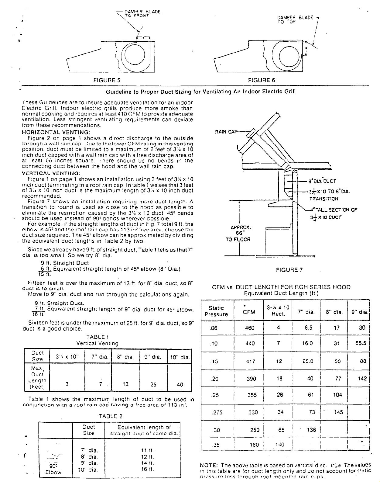
9. Attach !he damoer as shown in Figure 5 for vertical discharge or
Fig. 6 for horizontal discharge.
10. Lift the hood into position. Mark location of four mounting holes.
11. Remove hood and start all four screws in center of narrow neck of
keyhole slot marked on cabmet bottom.
72. Lift the hood into posrrion simultaneously feeding the electrical
wire through the knockout. Fojlow aoplicable local codes and/or
latest Nattonal Electrrcal Code for electrical connector to be used at
field wiring entrance.
13. Tighten screws to secure hood. Be sure screw head is in narrow
neck of keyhole slot.
14. Install proper duct work. See page 2.
16. COmplete electrical wiring -in junction box according to the
National Electrical Code and applicable Local Codes. NOTE: This
Unit must be permanently grounded in accordance with the National
Electrical Code and applrcable Local codes.
16. Replace junction box cover,
17. Replace blower. See page 3 for proper blower orientation
18. Replace blower cover. light frame assembly and filters.
NOTE: It has been found that a large part of the energy loss of the
average home IS due to outslde air InfIltratIng the structure, Sea)
around duc!work wncre It passes through outside walls or ceilrng.
Sea-l around electrical wrrrng also.
L4
. .
.
.
FIGURE 3
,-LIGHT FRAME
COVER
FIGURE 4
RGHt!S3m-25
FIGURE 2
L V,lPil,G -,:.r,:*=w;
\
i
"I
,/-9LOWER
- J’JYCTION
-BLOWER CRADLE
RETAINING
ROD
90x
.
.
RGH 8300-l '%
- CAMPER BLADE
~~~~
TO FRONT
.
’
.
b
FIGURE 5 FIGURE 6
.
These Guidelines are to insure adequate ventilation for an indoor
Electric Grill. Indoor electnc grills produce more smoke than
normal cooking and requtres at least 41 O CFM to provide adequate
ventllatton. Less sinngent venttlating requtrements can deviate
from these recommendations.
HORIZONTAL VENTING:
Frgure 2 on page 1 shows a direct discharge to the outside
through a wall rain cap. Due to the lower CFM rating in this venting
posItron. duct must be limtted to a maximum of 2 feet of 3;/r x 10
Inch duct capped with a wall rain cap with a free discharge area of
al least 66 inches square. There should be no bends in the
connec:lng duct between the hood and the wall ratn cap.
VERTICAL VENTING:
Figure 1 on page 1 shows an installation using 3 feet of 3% x 10
inch duct term:nating in a roof rain cap. In table 1 we see that 3 feet
of 3:. x 10 inch duct is the maxlmum lengtn of 3’;; x 10 Inch duct
recommended.
Figure 7 shcws an installation requiring more duct length. A
transr!lon to round is used as close to the hood as possible to
elrmtnate the restriction caused by the 3’; x 10 duct. 4jJ bends
should be used Instead of 90g bends wherever possible.
For example, if the straight lengihs of duct In FIN. 7 total 9 ft. the
elbow
IS
duct size required. The -15; elbow can be approximated by dividing
the equivalent duct !engths In Table 2 by two.
dia.
duct
duct IS
I
COnjunct;on wltn a roof rain cap i-,avlng a free area of 113 II-I?.
.
.
45’ and the roof rain cap has 113 in’ free area. choose the
Since we already have9 ft. of straight duct, Table 1 tells us that 7”
IS
too small. So we try 8” dia.
9 ft. Straight Duct
6 Equrvalent straight length of 4.Y elbow (8” Dia.)
15 ft.
Frfteen feet is ever the maximum of 13 ft. for 8” dia. duct, so 8”
IS
to small.
!-dove to 9” dia. duct and run :hrough the calculations again.
9 ft. Straight Duct.
7 ft. Equrvalent stratght leng!h cf 9” dia. duct for 45” elbow.
i-6-K
Sixteen fee!
Duct
Size I
,uax
Duct
Length
(Feet)
Table 1 shows the maxlmum length of duct to be used In
IS
a gocd chotce.
--
under the maxrmum of 25 ft. for 9” dia. duct, so 9”
Vertical Venting
3’/. x 10”
3
l
90”
Elbow
TABLE I
7” dm I 8” dia.
I
Duct
Size
9” dia. 14 ft.
10” dta.
\
Guideline to Proper Duct Sizing for Ventilating An Indoor Electric Grill
9” dia.
I
7. 13
TABLE 2
Equivalent length of
straight ducr of same dia.
11 ft.
12 ft.
:6 ft.
1 10” dia. 1
25 40
FIGURE 7
CFM vs. DUCT LENGTH FOR F?GH SERIES HOOD
Equivalent Duct Length (ft.)
Static
Pressure
.06 460 4 8.5 17 30 i
.lO 440
/ cFh4 j 3-;;t:0 / 7” dia. 1 8” dia. 1 9” dia.1
I L I
7 16.0 31 55.5 1
I i
.15 417 12 25.0 50
.20
.25 355
.30 250 65 1 1361 -I
.35
c
NOTE: Tne above table
In lhls !able are for duct length only and co not account for Sldtic
pressure loss :hroucn roof mounted rain c. 0s
/
390 /
330
180
18
1
40 1
?40 i .;
IS
basec on-~ertlcal disc
77 /
I
IT&?. Thevaiues
142!
4
:
 Loading...