

Whirlpool RCH3660 User Manual
VENTED KITCHEN SHELF HOOD
FOR 120 V. OPERATION
AVhiTlDool
FOR VENTLESS INSTALLATION, DIS
REGARD THIS INSTRUCTION SHEET.
USE VENTLESS KIT INSTRUCTION
SHEET FOR MODEL RCH3660.
INSTALLATION INSTRUCTIONS
READ AND SAVE THESE INSTRUCTIONS
Before you begin, read the following instructions
completely and carefully. If followed, they will simplify
the installation job.
’ ^ORTANT: OBSERVE ALL GOVERNING CODES
AND ORDINANCES
SAVE THESE INSTRUCTIONS FOR THE LOCAL
ELECTRICAL INSPECTOR’S USE
KITCHEN
RANGE HOOD
MODEL
IMPORTANT
RH3330XL-1
BEFORE YOU USE YOUR SHELF HOOD:
Be sure your shelf hood is installed on an appropriate wall
strong enough to support this appliance.
NOTE: The shelf hood is designed to support a microwave
oven with a net weight of up to 75 pounds, plus approved
accessories, cookbooks, utensils, and food.
The area used for the installation must be suitable for the
size, function, and protection (from elements) of the shelf
hood.
FOR USE WITH WHIRLPOOL “J ” AND
LINE MICROWAVE OVENS
FOR USE OVER WHIRLPOOL CONVENTIONAL
GAS AND ELECTRIC RANGE COOKTOPS
THAT DO NOT HAVE A GRILLE.
TOOLS AND MATERIALS REQUIRED
• Drill, electric or ratchet drive, with 3/8", 3/16” and 1/8"
wood bit (for drilling starter holes) and 1-1/4" wood bit
(to drill an access hole in the cabinet or kitchen wall for
the electric power line.)
• One common and one phillips head screwdriver (to
secure hood mounting screws to the cabinet and hood
sheet metal parts).
• Pliers (for opening knockouts).
• Pencil, ruler and level for marking cabinet locations.
WARNING: THE WEIGHT OF THE MICROWAVE MAY
EXCEED YOUR LIFTING ABILITY. WE RECOMMEND
ASSISTANCE.
CAUTION: When mounting the shelf hood to a wall, you
must locate 2 studs in the wail. Do not attempt to install the
hood if the 2 wall studs are not found.
Be careful when drilling holes into a wall. Electrical wires and
water pipes may be concealed behind the wall covering.
/gg^/Tf
• Sabersaworkeyhoiesawforcuttingthewall or cabinet
openings.
• Caulking, metal snips, duct tape, ducts (with elbow and
transition, if necessary) and wall cap or roof cap, as
required.
Page 1
5-22-85
INSTALLATION
REQUIREMENTS
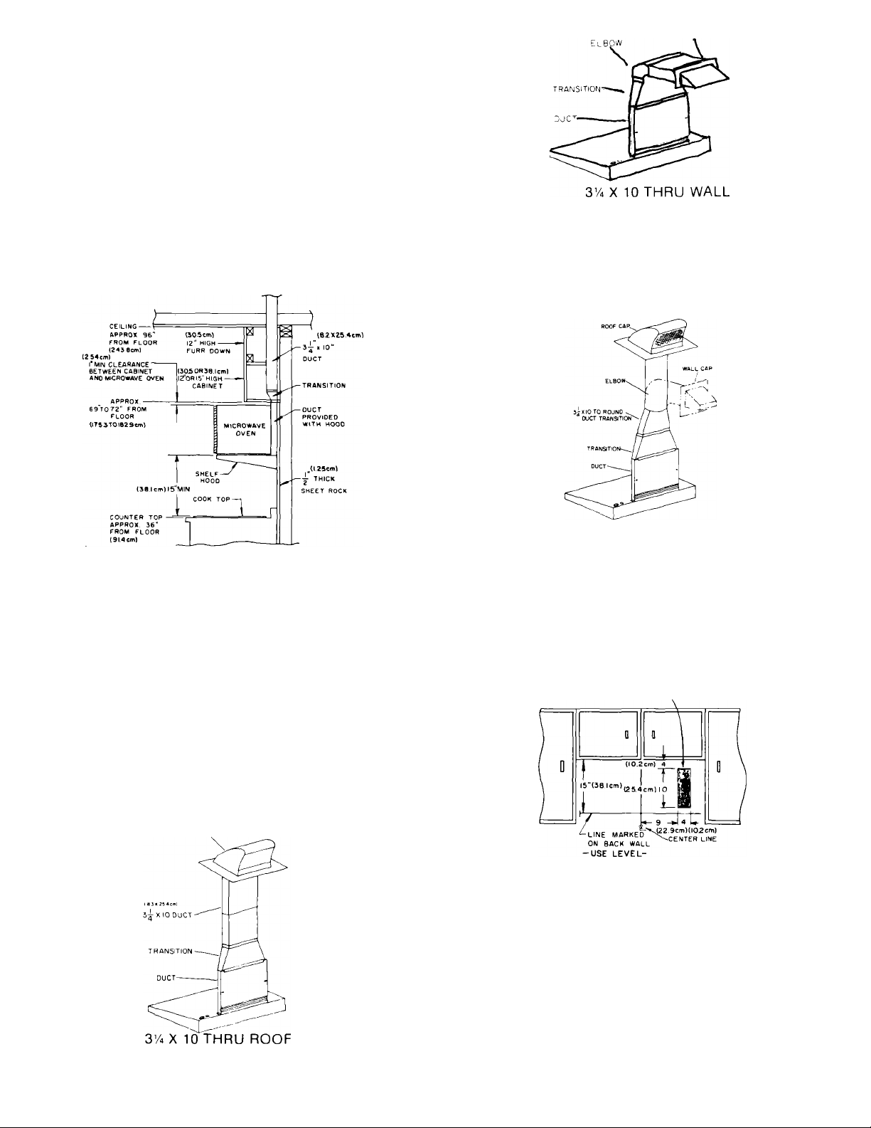
A. Space Requirements
A typical installation can be seen in Figure 1. Study Figure 1
before proceeding. The shelf hood requires an opening that
is 30" wide. It is recommended that the cabinet above the
cooktop- be a maximum of 15” high. This provides the
adequate space btween the range cooktop and the shelf
hood.
B. Electrical Requirements
A 120 Volt, 60 Hz, AC only, 20 Ampere fused electrical supply
is required (Time delay fuse or circuit breaker is
recommended). It is recommended that a separate circuit
serving only this appliance be provided.
(8.3 X 25.4 cm)
Figure 3
IMPORTANT: WALL AND ROOF CAPS MUST HAVE BACKDRAFT DAMPER.
NOTE: Ductwork, wall and roof caps not supplied with hood.
Figure 1
VENTING REQUIREMENTS
Before you begin, determine where the ductwork will run.
For best performance, keep the length of ductwork and the
number of elbows to a minimum.
Illustrated are some of the more common methods. (Figures
2,3, and 4).
IMPORTANT: THE VENTING SYSTEM MUST TERMINATE
TO THE OUTSIDE. DO NOT TERMINATE THE VENT IN AN
ATTIC OR OTHER ENCLOSED SPACE. THIS MAY RESULT
IN A FIRE HAZARD.
Figure 2
Page 2
Z'A" X 10 to ROUND (7" MIN. DIAMETER)
THRU ROOF
Figure 4
INSTALLATION
1. Select the area for Installation, making sure you have an
electrical supply available. See the shaded area (Figure 5).
This is the area the electrical supply must enter.
ELECTRICAL
ROUGH-IN AREA
Figure 5
CAUTION: Due to the amount of weight the shelf hood must
support, make sure the hood is mounted to two vertical 2x4
wall studs with the four lag bolts and into the wall covering
('h" sheet rock minimum) with the four anchor bolts. Lag
bolts and anchor bolts (eight in all) are supplied in the Instal
lation Assembly.
2. If the shelf hood is mounted to a wall that does NOT meet
the above recommendations, the weight of the microwave
oven may cause the hood to pull away from the wall resulting
in personal injury or property damage.
3. Mark a line on the back wall 15" down from the upper
cabinets centered between the side cabinets or the allotted
space. Use a level. (Figure 5).
 Loading...