

Whirlpool RC8700ED, RC8700EDB Installation Instructions Manual
Part No. 208040 A
4381589
© 1995
Benton Harbor, Michigan 49022
Printed in U.S.A.
Quick Reference
Table of Contents:
Pages
Before you start
Cutout dimensions
Clearance dimensions
Product dimensions
Tools and materials needed
Parts supplied
Electrical requirements
Venting requirements
Installation steps
Cooktop removal
Wiring diagram
Need assistance?
Check your Use and Care Guide for a toll-free number to call, or call
the dealer from whom you purchased the appliance when you:
Have questions about the cooktop installation or operation.
Need to obtain the name and number of an authorized service
company.
The dealer is listed in the Yellow Pages of your phone directory
under “Appliances — Household — Major — Service and Repair.”
When you call, you will need:
The cooktop model number.
The cooktop serial number.
Both numbers are listed on the model/serial rating plate, located on
the left side of the downdraft plenum.
Write both numbers down now before installing cooktop.
Model # ______________________ Serial # ______________________
1
1
1
1
1
1
4
2-3
4-5
Back cover
Back cover
IMPORTANT:
Read and save these instructions.
Installation Instructions
IMPORTANT:
Installer: Leave Installation Instructions with the homeowner.
Homeowner: Keep Installation Instructions for future reference.
Save Installation Instructions for local electrical inspector's use.
Part No.
208040 A
4381589
When you call, you will need the cooktop model
number and serial number. Both numbers can be
found on the model/serial rating plate located on
the left side of the plenum.
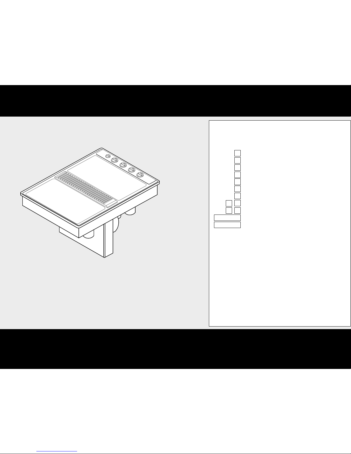
30" ELECTRIC
Downdraft Cooktop
Modules selected at time of purchase
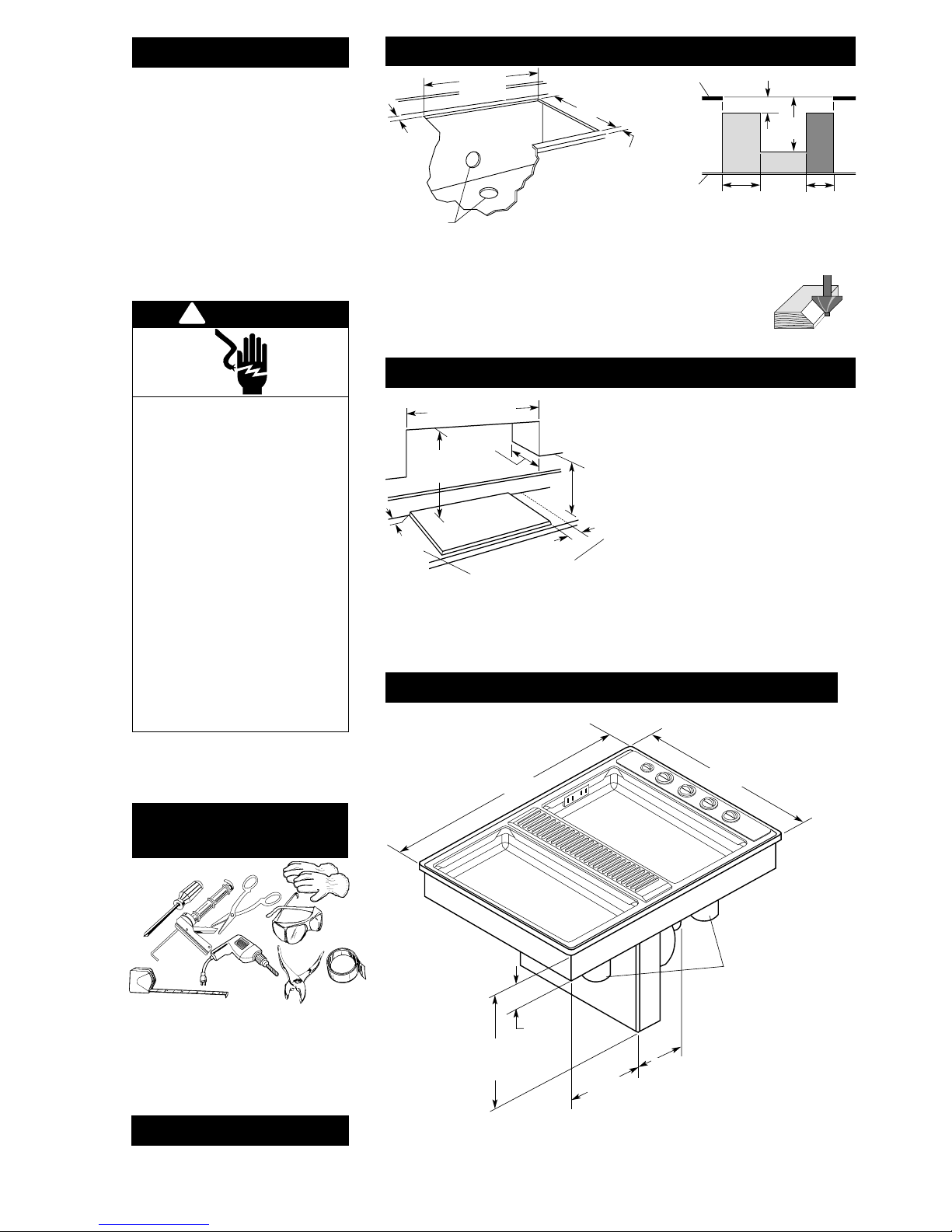
Cutout preparation:
Decorative laminate —
Chamfer all exposed edges to
prevent chipping laminate.
Cut radius corners and file to
smooth edges and to prevent
cracking.
Page 1
Cutout dimensions
Clearance dimensions
Before you start...
Important: Observe all governing codes
and ordinances.
Proper installation is your responsibility.
• Make sure you have everything necessary for
correct installation.
• Have a qualified technician install this cooktop.
• Comply with the installation clearances specified
on the model/serial rating plate.
Model/serial rating plate is located on the left side
of the downdraft plenum.
Cooktop location should be away from strong
draft areas, such as windows, doors and strong
heating vents or fans. Locate cooktop for
convenient use in kitchen.
Grounded electrical system is required. See
“Electrical requirements,” Page 4.
Venting duct must terminate outdoors.
All openings in the wall or floor where cooktop is
to be installed must be sealed.
This appliance is Not approved for use in mobile
homes.
*Copies of the standards listed may be obtained from:
National Fire Protection Association
Batterymarch Park
Quincy, Massachusetts 02269
!
WARNING
Electrical Shock Hazard
It is the customer’s responsibility to contact a
qualified electrical installer, to make sure that
the electrical installation is correct, and to
make sure the electrical installation follows the
National Electrical Code, ANSI/NFPA 70 —
latest edition*, and all local codes and
ordinances.
Take special care when cutting holes into a
wall. Electrical wires may be behind the wall
covering and could cause an electrical shock if
you touch them.
Disconnect the power to any electrical circuits
that could be affected by the installation of this
product.
Failure to do so could result in death or serious
injury.
Injury Hazard
To eliminate the risk of burns or fires, Do Not
install cabinets or store things above the
cooktop. If cabinets are already installed above
the cooktop, install a range hood to the
bottom of the cabinet to prevent reaching over
a heated cooking surface. The range hood
should stick out a minimum of 5 inches
(12.7 cm) from the front of the cabinets.
Reaching over a heated cooking surface could
result in a serious burn or other injury.
If cabinet has drawers, drawers will need to
be removed and drawer fronts installed on
front of cabinet.
1-7/8" (4.8 cm)
minimum space
to front edge of
countertop
Install rear
wall junction
box in shaded
area. Darker
shaded area
is preferred.
Select required
duct cutout
(see Page 2 for
exhaust duct
cutout location).
Countertop must be
supported within
3" (7.6 cm) of cutout.
28-7/8"
(73.3 cm)
cutout width
15/16" (2.4 cm)
minimum
distance to
backsplash
or vertical
wall
20-7/8"
(53.2 cm)
cutout depth
Side clearance — 6" (15.2 cm) minimum
clearance between side of cooktop and
side wall is recommended for maximum
ventilation performance.
Rear clearance — 3/4" (1.9 cm) clearance
between rear edge of appliance and rear
wall is required.
Motor/blower clearance — 2" (5.1 cm)
minimum clearance between motor and
cabinet is required for proper cooling. 6"
(15.2 cm) clearance is recommended for
servicing access.
Do Not seal
cooktop to
countertop.
Minimum distance to nearest
combustible vertical surface extending
18" (45.7 cm) above cooktop
3/4"
(1.9 cm)
See Note**
for minimum
clearances.
18" (45.7 cm)
minimum
clearance upper
cabinet
to countertop
6" both sides
(15.2 cm)
Installation location
should provide
sufficient room for
removing grease
containers.
30" (76.2 cm) minimum
when higher than 18"
(45.7 cm)
13" (33 cm)
maximum
upper
cabinet
depth
tape measure
hand or
electric drill
metal
snips
duct tape
pliers
gloves
safety
glasses
caulking
gun with
weatherproof
caulking
Phillips
screwdriver
Not shown:
• wall or roof cap
• metal ductwork
• 2 sheet metal screws to attach transition duct to venting adapter
• Two U.L.-listed 1/2" conduit connectors
• Flexible, armored or non-metallic sheathed copper cable
(with grounding wire) that conforms to existing codes (see
“Electrical requirements” Page 4). Length required depends
on your installation.
• Twist-on connectors. Number and size will depend on your
installation. See “Electrical connection,” Page 5.
Tools and materials
needed:
Parts supplied:
Remove parts from packages. Check that all parts
were included.
• literature pack
• exhaust flow rate tester card
Product dimensions
Minimum base cabinet dimensions —
30" (76.2 cm) base cabinet
24" (61.0 cm) base cabinet depth
25" (63.5 cm) countertop depth
Blower can be
swiveled 90°.
3-3/4"
(9.5 cm)
burner box
depth
grease
containers
Appliance junction
box is located
under right side
of cooktop.
16-7/16"
(41.8 cm)
blower
housing
depth
29-7/8" (75.9 cm)
width
21-1/2" (54.6 cm)
depth
12-7/16"
(31.6 cm)
11-7/8"
(30.2 cm)
Note: 24" (61.0 cm) minimum when bottom of wood or metal
cabinet is protected by not less than 1/4" flame retardant
millboard covered with not less than No. 28 MSG sheet steel,
0.015" stainless steel, 0.024" aluminum or 0.020" copper.
30" (76.2 cm) minimum clearance between the top of the cooking
platform and bottom of unprotected wood or sheet metal.
**
5" (12.7 cm)
17"
(43.2 cm)
11"
(27.9 cm)
8"
(20.3 cm)
countertop
floor
Page 2
Venting requirements
WARNING
!
Fire Hazard
The venting system MUST end outdoors.
Do Not end the ductwork in an attic, wall,
ceiling or other enclosed space.
Do Not use 4" laundry-type wall caps.
Do Not use plastic-type duct.
Do Not block the flow of ventilation air.
Failure to follow these instructions could result
in a fire.
Duct materials needed for installation is not
supplied.
Before making cutouts, make sure there is proper
clearance within the wall or floor for the exhaust
duct.
Do Not cut a joist or stud unless absolutely
necessary. If a joist or stud must be cut, then a
supporting frame must be constructed.
Determine which venting method to use. See
“Venting methods,” Page 2.
Next, determine the equivalent duct length using
chart on Page 3. This cooktop is equipped with a
dual range blower. The equivalent duct length (not
actual) determines whether blower is set at the
“Low” or “High” range. The blower is set at the
“Low” range setting at the factory.
The blower housing must be rotated or swiveled to
the proper angle needed for your installation. The
blower can be swiveled 90°. The blower maybe
rotated horizontally or vertically. Reach through the
ventilation chamber to loosen, but Do Not remove,
the nuts around blower inlet to adjust the blower.
This downdraft cooktop is rated at 60 feet of
straight duct.
• If duct length is 10 feet (3 m) or less, 5" diameter
round ductwork may be used.
• If duct length is more than 10 feet (3 m), use 6"
diameter round or 3-1/4" x 10" rectangular duct.
Thermal breaks: In areas of extreme cold weather, it
may be necessary to provide a short length of
nonmetallic duct as close to the wall as possible to
prevent thermal conduction along the metal duct.
For altitudes above 4,500 ft (1,350 m), reduce
recommended duct run by 20%.
For the most efficient and
quietest operation:
Use 26-gauge minimum galvanized or 25-gauge
minimum aluminum metal duct. Poor-quality
pipe fittings can reduce air flow. (Note: Local
codes may require a heavier-gauge material.)
Flexible metal duct is Not recommended.
Do Not exhaust more than one downdraft
cooktop into a single duct system.
The length of duct and number of elbows
should be kept to a minimum to provide
efficient performance.
The size of the duct should be uniform.
Use no more than three 90° elbows.
Do Not install two elbows together.
Make sure there is a minimum of 18" (45.7 cm)
of straight duct between the elbows if more
than one elbow is used. (Elbows too close
together cause excess turbulence that reduces
airflow.)
Do Not use a 5" elbow in a 6" or 3-1/4" x 10"
system. Instead, use a 5" to 6" transition
followed by a 6" elbow, or a 5" to 3-1/4" x 10"
elbow transition.
Do Not reduce back to 5" system after using 6"
or 3-1/4" x 10" fittings.
Avoid forming handmade crimps. Handmade
crimps may restrict airflow.
Use the recommended duct caps for proper
performance. If an alternate wall or roof cap is
used, be certain cap size is not reduced and that
it has a backdraft damper.
Use duct tape to seal all joints in the duct
system.
Use caulking to seal exterior wall or roof
opening around the cap.
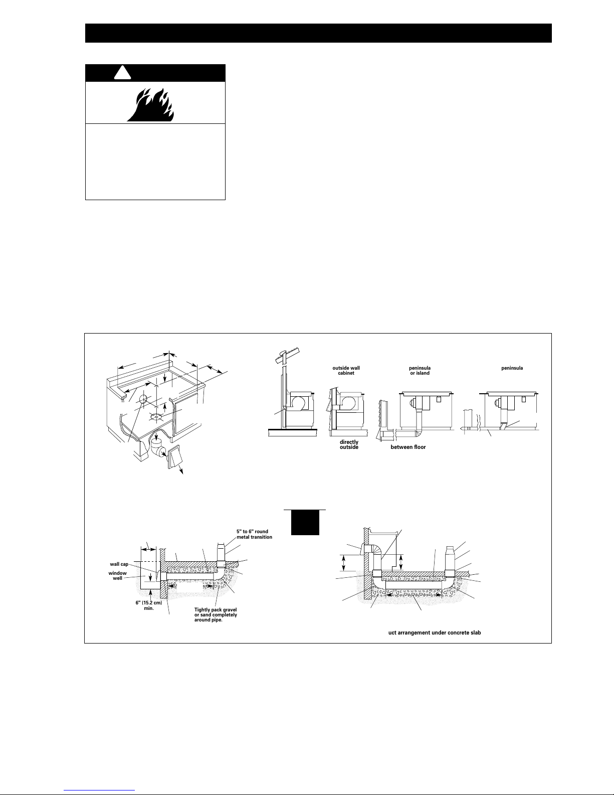
The cooktop may be vented through the rear wall or
floor. Common venting methods and the types of
materials needed are shown.
Make sure there is proper clearance within the wall or
floor for exhaust duct before making cutouts.
a
a
a
a
a
a
a
aa
a
aa
aa
a
a
a
a
a
a
a
a
aa
a
a
aa
a
a
a
a
a
aa
aa
a
a
a
a
a
a
a
a
a
a
a
a
a
a
a
a
a
a
a
a
a
aa
a
a
a
a
a
a
a
a
a
a
a
a
a
a
a
a
a
a
a
a
a
a
a
a
a
a
aa
a
aa
aaa
a
a
a
a
a
a
a
aa
a
a
a
aaa
window
well
wall cap
6" (15.2 cm)
min.
Tightly pack gravel
or sand completely
around pipe.
5" to 6" round
metal transition
6" round metal duct
6" round
PVC coupling
6" round
sewer pipe
6" round
90° PVC sewer pipe elbow
concrete
slab
42’ (10.7 m)
max.
6" round
PVC coupling
12" (30.5 cm)
minimum
6" round
PVC sewer
pipe
Seal the space
between the
outside of wall
cap inlet inside
of PVC coupling
with caulking
metal.
optional duct arrangement through window well under concrete slab
a
a
aa
a
aaa
a
a
a
a
a
a
a
aa
a
a
aa
a
a
a
a
a
aa
aa
a
a
a
a
aa
a
a
a
a
a
a
a
a
a
a
a
a
a
a
a
aa
a
a
a
a
a
a
a
a
a
a
a
a
a
a
a
a
a
aa
a
aaa
a
a
a
a
a
a
a
aa
a
a
aa
a
a
a
a
a
aa
a
inside wall
cabinet
3-1/4" x 10"
transition
elbow
3-1/4" x 10"
transition
elbow
inside wall to roof
or overhang
optional duct arrangement under concrete slab
outside wall
cabinet
directly
outside
peninsula
or island
peninsula
between floor joists
cabinet toe space
to outside
wall cap
6" round PVC
coupling
6" round PVC
sewer pipe
6" round metal duct
Tightly pack gravel
or sand completely
around pipe.
5" to 6" round metal transition
6" round metal duct
6" round PVC coupling
concrete slab
6" PVC sewer pipe
6" round 90°
PVC sewer
pipe elbow
6" round 90°
PVC sewer
pipe elbow
16" (40.6 cm)
maximum
12" minimum
(30.5 cm)
30' (9.1 m)
maximum
14-3/4"
(37.5 cm)
Venting methods
28-7/8"
(73.3 cm)
20-7/8"
(53 cm)
6-15/16"
(17.6 cm)
17-1/2"
(44.5 cm)
opening
for venting
through floor
opening for venting
through rear wall
SBCCI
 Loading...