

CONSUMER SERVICES TECHNICAL
EDUCATION GROUP PRESENTS
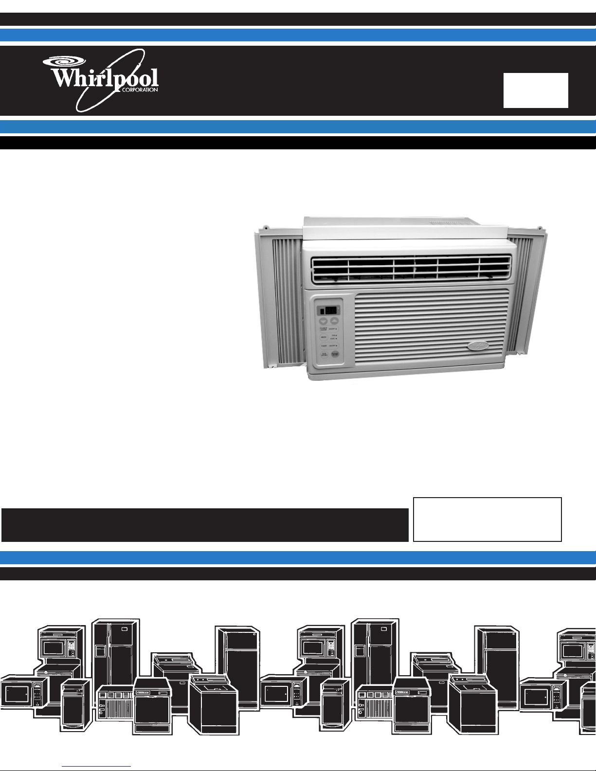
“P” MODEL AIR
CONDITIONER
R-94
JOB AID
Part No. 8178039

FORWARD
This Whirlpool Job Aid, “P” Model Air Conditioner (Part No. 8178039), provides the technician with
information on the installation and service of the “P” Model Air Conditioner. It is to be used as a
training Job Aid and Service Manual. For specific information on the model being serviced, refer
to the “Use and Care Guide,” or “Tech Sheet” provided with the air conditioner.
The Wiring Diagrams and Strip Circuits used in this Job Aid are typical and should be used for
training purposes only. Always use the Wiring Diagram supplied with the product when servicing
the unit.
GOALS AND OBJECTIVES
The goal of this Job Aid is to provide detailed information that will enable the service technician to
properly diagnose malfunctions and repair the “P” Model Air Conditioner.
The objectives of this Job Aid are to:
• Understand and follow proper safety precautions.
• Successfully troubleshoot and diagnose malfunctions.
• Successfully perform necessary repairs.
• Successfully return the air conditioner to its proper operational status.
WHIRLPOOL CORPORATION assumes no responsibility for any repairs made
on our products by anyone other than Authorized Service Technicians.
Copyright © 2001, Whirlpool Corporation, Benton Harbor, MI 49022
- ii -

TABLE OF CONTENTS
Page
GENERAL............................................................................................................................... 1-1
Safety First......................................................................................................................... 1-1
Electrical Power Supply & Grounding Requirements ................................................... 1-1
Weight Handling Requirements.................................................................................... 1-2
Electrostatic Discharge (ESD) Sensitive Electronics.................................................... 1-2
Whirlpool Model & Serial Number Designations ................................................................ 1-3
Model & Serial Number Label Location ............................................................................. 1-4
Specifications..................................................................................................................... 1-5
Whirlpool Air Conditioner Warranty ................................................................................... 1-6
INSTALLATION INFORMATION ........................................................................................... 2-1
COMPONENT ACCESS ......................................................................................................... 3-1
Component Locations ........................................................................................................ 3-1
Removing The Front Grille Assembly & Cabinet ............................................................... 3-2
Removing The Control Panel & Display PCB .................................................................... 3-4
Removing The Power Cord ............................................................................................... 3-5
Removing The Thermistor, The Capacitor, & The Main PCB ............................................ 3-6
Removing The Fan Motor .................................................................................................. 3-8
Removing The Overload Protector And The Compressor ............................................... 3-12
Removing The Evaporator ............................................................................................... 3-14
Removing The Condenser ............................................................................................... 3-16
COMPONENT TESTING ........................................................................................................ 4-1
Thermistor.......................................................................................................................... 4-1
Line Fuse ........................................................................................................................... 4-2
Capacitor ........................................................................................................................... 4-2
Fan Motor ......................................................................................................................... 4-3
Overload Protector............................................................................................................. 4-4
Compressor ....................................................................................................................... 4-4
WIRING DIAGRAMS .............................................................................................................. 5-1
Wiring Diagram (Models ACD052PK & ACM062PK) ........................................................ 5-1
Wiring Diagram (Models ACQ052PK & ACQ062PK) ........................................................ 5-2
- iii -

— NOTES —
- iv -
GENERAL
SAFETY FIRST
Your safety and the safety of others is very important.
We have provided many important safety messages in this Job Aid and on the appliance. Always
read and obey all safety messages.
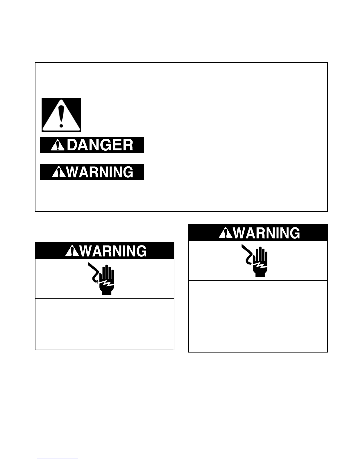
This is the safety alert symbol.
This symbol alerts you to hazards that can kill or hurt you and others.
All safety messages will follow the safety alert symbol and either the word
“DANGER” or “WARNING.” These words mean:
You can be killed or seriously injured if you don’t
immediately follow instructions.
You can be killed or seriously injured if you don’t
follow instructions.
All safety messages will tell you what the potential hazard is, tell you how to reduce the chance
of injury, and tell you what can happen if the instructions are not followed.
ELECTRICAL POWER SUPPLY &
GROUNDING REQUIREMENTS
Electrical Shock Hazard
Disconnect power before servicing.
Replace all panels before operating.
Failure to do so can result in death or
electrical shock.
Electrical Shock Hazard
Plug into a grounded 3-prong outlet.
Do not remove ground prong.
Do not use an adapter.
Do not use an extension cord.
Failure to follow these instructions can
result in death, fire, or electrical shock.
1-1
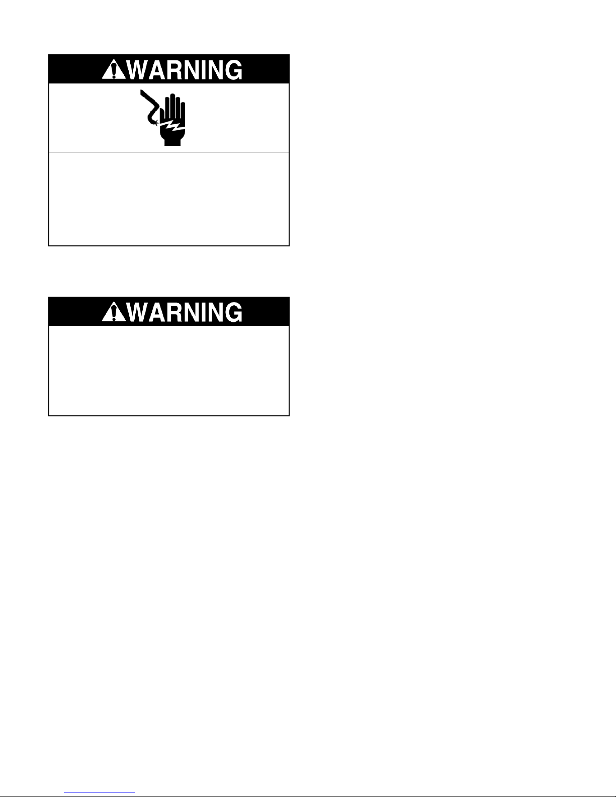
Electrical Shock Hazard
ELECTROSTATIC DISCHARGE
(ESD) SENSITIVE ELECTRONICS
ESD problems are present everywhere. ESD
may damage or weaken the electronic control
assembly. The new control assembly may appear to work well after repair is finished, but
failure may occur at a later date due to ESD
stress.
Connect green ground wire to ground
screw.
Failure to do so can result in death or
electrical shock.
WEIGHT HANDLING
REQUIREMENTS
Excessive Weight Hazard
Use two or more people to move and
install the air conditioner.
Failure to do so can result in back, or
other injury.
• Use an antistatic wrist strap. Connect the
wrist strap to a green ground connection
point or unpainted metal in the appliance; or
touch your finger repeatedly to a green ground
connection point or unpainted metal in the
appliance.
• Before removing the part from its package,
touch the antistatic bag to a green ground
connection point or unpainted metal in the
appliance.
• Avoid touching electronic parts or terminal
contacts. Handle the electronic control assembly by the edges only.
• When repackaging the failed electronic control assembly in an antistatic bag, observe
the above instructions.
1-2
WHIRLPOOL MODEL & SERIAL NUMBER DESIGNATIONS
MODEL NUMBER
MODEL NUMBER A C Q 05 2 P K 0
PRODUCT GROUP:
A = AIR CONDITIONER
PRODUCT IDENTIFICATION:
C = WARRANTY
D = DEHUMIDIFIER
O = ROOM A/C CABINETS
MODEL TYPE:
C = CASEMENT
E = ELECTRIC PUMP
H = HEAT PUMP
M = VALUE SERIES
P = PLUG-IN (7.5 AMPS OR LESS)(BEFORE 1999)
P = PREMIUM / ELECTRONICS MODELS (AFTER 1998)
Q = DESIGNER STYLE
R = REVERSE CYCLE WITH ELECTRIC HEAT
S = SLIDER
U = THROUGH-WALL
W = THROUGH-WALL (BUILT-IN)
APPROXIMATE CAPACITY: (30,000 B.T.U. / HR. MAXIMUM)
ELECTRICAL CODE:
2 = 115V, 60 HZ, 1 PHASE
3 = 230V, 60 HZ, 1 PHASE
4 = 230V-208V, 60 HZ, 1 PHASE
5 = 208V, 60 HZ, 2 PHASE
FEATURE CODE:
“P” MODEL
YEAR OF INTRODUCTION:
H = 1999. J = 2000, K = 2001
ENGINEERING CHANGE:
0, 1, 2, ETC.
SERIAL NUMBER
SERIAL NUMBER QL L 08 08012
MANUFACTURING RESPONSIBILITY
YEAR OF PRODUCTION:
K = 2000, L = 2001, M = 2002
WEEK OF PRODUCTION:
8th WEEK
PRODUCT SEQUENCE NUMBER
1-3
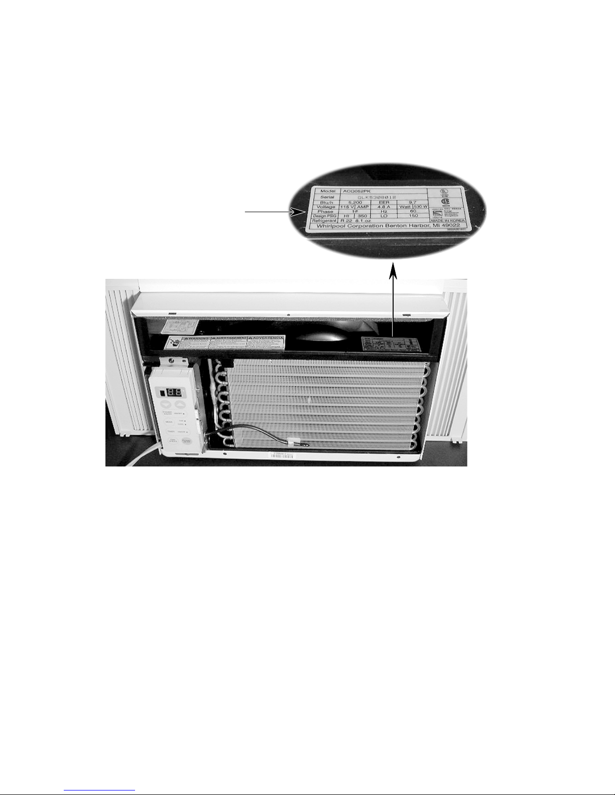
MODEL & SERIAL NUMBER LABEL LOCATION
The Model/Serial Number label location is shown below.
Model & Serial
Number Location
1-4
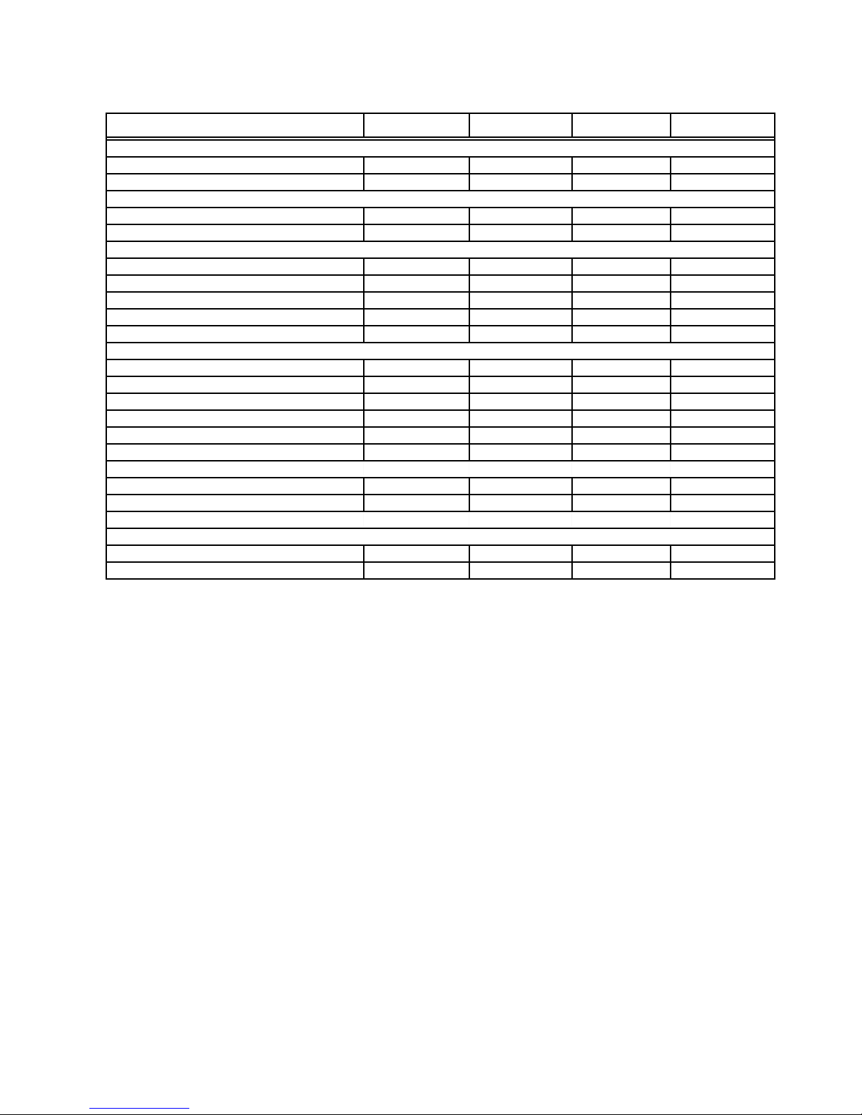
SPECIFICATIONS
Model Number ACD052PK ACM062PK ACQ052PK ACQ062PK
Ratings
BTU - Cool 5000 6000 5200 6000
Energy Efficiency Rating # 9.7 9.7 9.7 9.7
Air Features
Air Flow on Turbo (CFM) 14 0 140 14 0 1 4 0
Air Flow on Low (CFM) 115 115 115 115
Features
Cooling Speed Selections 2 3 3 3
Timer-Clock (On/Off) No No Yes Yes
Power Saver No No Yes Yes
Fan Only Yes-1 Speed Yes-1 Speed Yes-3 Speed Yes-3 Speed
Remote No No Yes Yes
Electrical
Volts 115 115 115 115
Frequency (Hz) 60 6 0 60 6 0
Amps (Cooling) 4.8 5.8 5.0 5.8
Fuse Size (Amps) 15 15 15 15
Power Cord Length (ft) - Cabinet to Wall 6 ft. 6 ft. 6 ft. 6 ft.
Power Cord Length (m) - Cabinet to Wall 1.8 m. 1.8 m. 1.8 m. 1.8 m.
Exterior
Fan Control Rotary Rotary Electronic Electronic
Thermostat Control Rotary Rotary Electronic Electronic
Miscellaneous
Warranty
Full 1 Year 1 Year 1 Year 1 Year
Full Sealed System 1 Year 5 Years 5 Years 5 Years
1-5

WHIRLPOOL AIR CONDITIONER WARRANTY
LENGTH OF
WARRANTY:
FULL ONE-YEAR
WARRANTY
FROM DATE OF
PURCHASE.
FULL FIVE-YEAR
WARRANTY
FROM DATE OF
PURCHASE.
(THIS WARRANTY
DOES NOT APPLY
TO MODEL
ACD052PK.)
WHIRLPOOL
WILL PAY FOR:
Replacement parts
and repair labor costs
to correct defects in
materials or workmanship. Service must be
provided by a Whirlpool-designated
service company.
Replacement parts
and repair labor costs
to correct defects in
materials or workmanship in the sealed
refrigeration system.
These parts are:
1. Compressor
2. Evaporator
3. Condenser
4. Accumulator
5. Conecting Tubing
Service must be
provided by a Whirlpool-designated
service company.
WHIRLPOOL WILL NOT PAY FOR:
A. Service calls to:
1. Correct the installation of the air conditioner.
2. Instruct you how to use the air conditioner.
3. Replace house fuses or correct house
wiring.
4. Clean or replace the air filter.
B. Pickup and delivery. The air conditioner is
designed to be repaired in the home.
C. Damage to the air conditioner caused by
accident, misuse, fire, flood, acts of God,
or use of products not mentioned in the
Use and Care Guide.
D. The removal or reinstallation of the air
conditioner if it is installed in an overhead
or other inaccessible location, or is not
installed in accordance with published installation instructions.
E. Repairs to parts or systems resulting from
unauthorized modifications made to the
appliance.
F. Replacement parts or repair labor costs for
units operated outside the United States or
Canada.
WHIRLPOOL CORPORATION SHALL NOT BE LIABLE FOR INCIDENTAL OR CONSEQUENTIAL DAMAGES. Some states or provinces do not allow the exclusion or limitation of incidental
or consequential damages, so this exclusion or limitation may not apply to you. This warranty
gives specific legal rights and you may also have other rights which vary from state-to-state or
province-to-province.
Outside the United States and Canada a different warranty may apply. For details, please
contact your local Whirlpool dealer.
If you need service, first see the “Troubleshooting” section of the Use & Care Guide. After checking “Troublesooting,” additional help can be found by checking the “Requesting Assistance Or
Service” section, or by calling the Whirlpool Consumer Assistance Center telephone number, 1-
800-253-1301, from anywhere in the U.S.A. For service in Canada, see “If You Need Assistance
Or Service In Canada” in the Use and Care Guide for the service branch in your area.
1-6
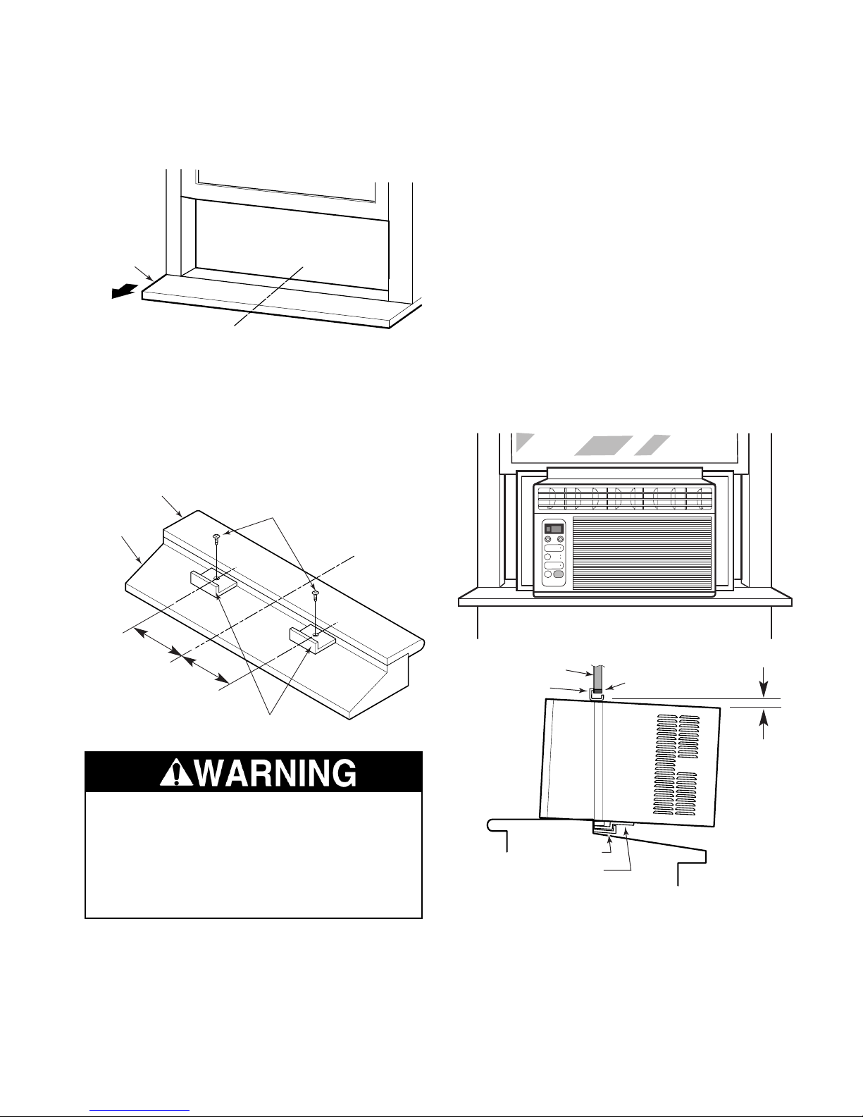
INSTALLATION INFORMATION
1. Open the window and mark the centerline
of the inner sill.
Inner Sill
Room
Centerline
2. Use two short screws, and attach the two
L-brackets 8˝ from both sides of the
centerline so they are flush against the
back of the inner sill, with the short side of
the bracket positioned vertically.
Inner Sill
Short Screws
Outer Sill
INSIDE
Centerline
IMPORTANT NOTES:
• Make sure that you maintain a good grip
on the air conditioner so that it does not
fall out of the window opening during the
installation.
• Make sure that you center the unit in the
window so that the L-brackets mate with
the bottom guides. If the unit is not centered properly, it could slide out of the
opening.
3. Carefully lift the air conditioner, and center
it in the window opening, then slide it into
place so that the bottom guides drop into
the two L-brackets you installed in step 2.
8″
(20.3 cm)
OUTSIDE
8″
(20.3 cm)
L-Brackets
Excessive Weight Hazard
Use two or more people to move and
install the air conditioner.
Failure to do so can result in back, or
other injury.
Window Frame
Upper Guide
L-Bracket
Bottom Guide
Seal
about
1/4″
(6.3 mm)
4. Lower the window sash so it is behind the
upper guide of the air conditioner. NOTE:
the back of the air conditioner should tilt
down slightly, as shown above.
2-1

REMOVING THE AIR CONDITIONER
FROM THE WINDOW
Excessive Weight Hazard
Use two or more people to move and
install the air conditioner.
Failure to do so can result in back, or
other injury.
1. Unplug the air conditioner or disconnect
the power.
2. Remove the L brackets and screws that
are installed through the top and bottom of
the guide panels.
L Bracket
Short Screw
Sash
Seal
3. Close the guide panels.
4. Raise the window sash and carefully tilt
the air conditioner backward to drain any
condensate water in the base.
5. Lift the air conditioner from the window
and remove the sash seal from between
the windows.
Wood Screw
2-2

COMPONENT ACCESS
This section instructs you on how to service each component inside the air conditioner. The
components and their locations are shown below.
COMPONENT LOCATIONS
Overload Protector
Compressor
Capacitor
Control Panel
& Display PCB
Main PCB
Condenser
Fan Motor
Thermistor
Evaporator
3-1

REMOVING THE FRONT GRILLE ASSEMBLY & CABINET
b) Remove the screw from the grille as-
sembly.
Electrical Shock Hazard
Disconnect power before servicing.
Replace all panels before operating.
Failure to do so can result in death or
electrical shock.
NOTE: Sharp edges may be present.
1. Unplug the air conditioner or disconnect
the power.
2. Remove the air conditioner from the window (see page 2-2 for the procedure).
3. To remove the front grille:
a) Pull out on the two indented areas on
both sides of the grille to release the
tabs from the clips, and open the grille
as far as it will go.
Indent
Clip & Tab
Screw
c) Raise the grill and secure it.
d) Pull out on both sides of the grille frame
and unhook the tabs from the cabinet
slots.
Grille Frame
Slot
Pull Forward
Pull Out
Pull Grille
Forward
3-2

e) Pull the bottom of the grille assembly
out, unhook it at the top, and remove
the assembly.
Unhook
c) Remove the five side screws and the
four rear screws.
Pull Out
4. To remove the cabinet:
a) Remove the four screws from both cur-
tain frames.
b) Slide the left and right curtain frame
assemblies off the sides of the unit.
2 Screws
(3 On Other
Side)
d) Lift the cabinet off the unit.
4 Screws
Slide Out
4 Curtain
Frame Screws
3-3

REMOVING THE CONTROL PANEL & DISPLAY PCB
5. Push down on the top two clips of the control panel and unhook them from the chassis slots, then lift the panel assembly off
the unit, and remove it.
Electrical Shock Hazard
Disconnect power before servicing.
Replace all panels before operating.
Failure to do so can result in death or
electrical shock.
NOTE: Sharp edges may be present.
1. Unplug the air conditioner or disconnect
the power.
2. Remove the air conditioner from the window (see page 2-2 for the procedure).
3. Remove the grille assembly from the air
conditioner (see page 3-2 for the procedure).
4. Press in on the locking arms and disconnect the two connectors from the display
PCB.
Connector
(1 of 2)
Control Panel
Clips
6. Remove the two screws from the display
PCB, unclip the board from the control
panel, and remove the board.
Screw
Clips
Screw
Press In On
Locking Arm
Display PCB
3-4

REMOVING THE POWER CORD
Electrical Shock Hazard
Disconnect power before servicing.
Replace all panels before operating.
Failure to do so can result in death or
electrical shock.
7. Remove the top and bottom screws from
the control panel brackets.
Screw
Control Panel
Screw
NOTE: Sharp edges may be present.
1. Unplug the air conditioner or disconnect
the power.
2. Remove the air conditioner from the window (see page 2-2 for the procedure).
3. Remove the grille assembly and cabinet
from the air conditioner (see pages 3-2
and 3-3 for the procedures).
4. Remove the machine screw from the green
ground wire.
Wire Tie
Ground Wire
Machine Screw
8. Remove the screw from the power cord
strain relief clamp and remove the clamp
from the power cord.
Strain Relief
Screw
Ribbed Power
Cord Lead
Smooth Power
Cord Lead
5. Disconnect the ribbed power cord lead
from the capacitor terminal and the smooth
lead from the main PCB relay terminal.
6. Pull the two power cord leads and the
green ground wire through the wire tie.
NOTE: If the wire tie is too tight, you will
have to cut it and install a new one around
the wiring after you install the new cord.
Electrical Shock Hazard
Connect green ground wire to ground
screw.
Failure to do so can result in death or
electrical shock.
NOTE: Be sure to reinstall the ribbed power
cord lead on the capacitor terminal, the smooth
lead on the main PCB relay terminal, and the
green ground wire to the ground screw.
3-5

REMOVING THE THERMISTOR,
THE CAPACITOR, & THE MAIN PCB
Electrical Shock Hazard
Disconnect power before servicing.
Replace all panels before operating.
Failure to do so can result in death or
electrical shock.
NOTE: Sharp edges may be present.
1. Unplug the air conditioner or disconnect
the power.
b) Disconnect the 4-wire connector from
the main PCB at CN-TH1. NOTE: You
may have to move some of the wire
bundles out of the way to access the
connector.
2. Remove the air conditioner from the window (see page 2-2 for the procedure).
3. Remove the grille assembly and cabinet
from the air conditioner (see pages 3-2
and 3-3 for the procedures).
4. To remove the thermistor:
a) Unclip the thermistor from the front of
the unit.
Thermistor
Connector CN-TH1
c) Pull the thermistor through the chassis
hole and remove it.
Unclip
Thermistor
3-6

5. To remove the capacitor:
a) Remove the two screws from the top
and bottom of the control panel assembly.
Screw (black)
e) Disconnect the wires from the following
capacitor terminals:
• Yellow wire to 2-lug terminal (FAN).
• Red wire to 3-lug terminal (HERM).
• Black, (2) orange, and ribbed power
cord lead to 4-lug terminal (C).
Control Panel
Screw
b) Pull the housing out the unit and posi-
tion it as shown below.
Fan Motor
Connector
Strap
Capacitor
4-Lug
Terminal
(C)
2-Lug
Terminal
(FAN)
3-Lug
Terminal
(HERM)
6. To remove the main PCB:
a) If not already done, remove the capaci-
tor (see step 5). NOTE: It is not necessary to perform step 5e.
b) Remove the three screws from the main
PCB.
Blue Wire &
Smooth Power
Cord Lead
4-Wire
Connector
c) Discharge the capacitor by touching
one lead of a 20,000 Ω resistor to the
common (C) terminal, and the other
lead to each of the other two terminals (marked FAN & HERM next to
the terminals).
d) Slide the capacitor out of the mounting
strap.
Screw
(1 of 3)
6- & 11-Wire
Connectors
c) Disconnect the following connectors
from the main PCB:
• Fan motor connector (see the photo
to the left for the location).
• 6- & 11-wire connectors (brown wires).
• 4-wire connector (from thermistor).
• Smooth power cord lead from lug 3
and blue wire from lug 4 of the relay.
d) Unclip the PCB from the holder.
3-7

REMOVING THE FAN MOTOR
Electrical Shock Hazard
Disconnect power before servicing.
Replace all panels before operating.
Failure to do so can result in death or
electrical shock.
NOTE: Sharp edges may be present.
5. Remove the two screws from the top air
guide cover and remove the cover.
Screw
Top Air
Guide Cover
1. Unplug the air conditioner or disconnect
the power.
2. Remove the air conditioner from the window (see page 2-2 for the procedure).
3. Remove the grille assembly and cabinet
from the air conditioner (see pages 3-2
and 3-3 for the procedures).
4. Remove the top and bottom screws from
the control panel brackets and unclip the
thermistor from the front of the evaporator,
then move the control panel assembly out
of the chassis pan.
Screw
Control Panel
Screw
Screw
6. Lift both ends of the evaporator out of the
front air guide and pull the right side out so
you can access the cover behind it. NOTE:
Be careful not to bend the bottom of the
fins on the evaporator when you handle it.
Evaporator
Front Air
Guide
Cover
Pull
Out
Unclip
Thermistor
Lift Evaporator
Out Of Guide
3-8

7. Unhook the right side of the front air guide
cover from the front air guide, then lift the
cover out of the guides on both sides, push
the left side out so that it unhooks, and
remove the cover.
10. Remove the screw from the left side of the
rear air guide, and unhook the two tabs
from the condenser slots on the right side.
Rear Air Guide
Front Air
Guide
Unhook
Front Air
Guide
Cover
Lift From
Guide
8. Pull the blower off the front shaft of the fan
motor. NOTE: It may be necessary to
remove the ring clamp if the blower cannot
easily be removed. If so, use a pair of
pliers and squeeze the ring tabs together,
and pull it off the hub.
Unhook
Screw
Unhook
Condenser
11. Remove the two screws from the front air
guide.
Blower
Pull Out
Ring Clamp
9. Carefully reposition the evaporator back
inside the front air guide in its normal
mounting position to protect it during the
rest of the procedure (see step 6).
Front Air
Guide Screws
12. Slide the front air guide assembly toward
the back of the unit until the left and right
side keys clear the slots in the chassis
pan. Lift the air guide assembly, and pull it
forward over the edge of the pan just
enough to allow access to the fan motor
mounting screws.
Lift
Slide Back
Chassis Pan
Slot (Each Side)
Continued on the next page
3-9
Front Air
Guide
Assembly
Key

13. Carefully push on the center hub and slide
the fan off the rear shaft of the fan motor,
then remove the fan and the rear air duct
(the duct is removed in the photo below).
Be careful not to damage the fins on the
condenser assembly.
Slide Back
15. Disconnect the fan motor connector from
the capacitor wire connector.
Capacitor
Connector
Fan Motor
Connector
16. Remove the two black mounting screws
from the fan motor brackets and remove
the motor.
17. Remove the green ground wire from the
fan motor bracket.
Screw
Condenser
Fan
14. Remove the ring clip from the fan hub with
a pair of pliers.
Screw
Green
Ground Wire
3-10

FAN MOTOR REINSTALLATION NOTES:
Electrical Shock Hazard
Connect green ground wire to ground
screw.
Failure to do so can result in death or
electrical shock.
1. Make sure that you reconnect the green
ground wire to the same bracket location
as before (next to the power cable).
2. Position the fan motor as shown in the
photo at the bottom of the previous page,
and mount the motor to the front air guide
with two black screws.
3. Note that the fan hub hole has a “key”
inside it. Position this key over the flat of
the motor shaft, and slide the fan onto the
shaft until the end is approximately 1/4˝
from the outside of the fan hub hole.
4. Squeeze the tabs on the ring clip and slide
the clip over the fan hub.
5. Install the blower on the front fan motor
shaft as far as the “stop” at the end of the
hub opening, then install the ring clip over
the hub.
3-11

REMOVING THE OVERLOAD PROTECTOR
AND THE COMPRESSOR
Electrical Shock Hazard
Disconnect power before servicing.
Replace all panels before operating.
Failure to do so can result in death or
electrical shock.
NOTE: Sharp edges may be present.
b) Disconnect the brown wire from the
compressor terminal, and the blue wire
from the overload protector terminal.
Brown
Wire
Blue
Wire
Overload
Compressor
Terminals
Protector
1. Unplug the air conditioner or disconnect
the power.
2. Remove the air conditioner from the window (see page 2-2 for the procedure).
3. Remove the grille assembly and cabinet
from the air conditioner (see pages 3-2
and 3-3 for the procedures).
4. To remove the overload protector:
a) Remove the hex cap nut and the nylon
flat washer from the terminal cover and
remove the cover.
Hex Cap Nut
& Nylon Flat
Washer
Terminal
Cover
REASSEMBLY NOTE: When you reinstall the
terminal cover on the compressor, make sure
that the overload protector is centered in the
gasket hole, and does not sit on any portion of
the gasket.
5. To remove the compressor:
a) Remove the overload protector (see
step 4).
b) Disconnect the red wire from the S (V)
terminal and the black wire from the
R (U) terminal of the compressor.
c) Remove the gasket.
Black
Wire
Red
Wire
3-12
Compressor
Terminals
Gasket

d) Braze on an access valve and dis-
charge the sealed system refrigerant
into a refrigerant recovery bag.
e) Disconnect the high side line from the
compressor, and the suction line from
the accumulator.
Suction Line
High Side Line
To Compressor
To Accumulator
g) Lift the compressor off the three rubber
shock mounts.
Rubber Shock
Mount
f) Remove the three 1/2˝ hex nuts and
bracket washers.
1/2˝ Hex Nut
Bracket Washer
(1 of 3)
3-13

REMOVING THE EVAPORATOR
Electrical Shock Hazard
Disconnect power before servicing.
Replace all panels before operating.
Failure to do so can result in death or
electrical shock.
NOTE: Sharp edges may be present.
1. Unplug the air conditioner or disconnect
the power.
2. Remove the air conditioner from the window (see page 2-2 for the procedure).
3. Remove the grille assembly and cabinet
from the air conditioner (see pages 3-2
and 3-3 for the procedures).
4. Remove the thermistor from the mounting
clip.
5. Pull the mounting clip off the evaporator
tubing and reinstall it on the new evaporator at the same location.
Remove Clip
6. Braze on an access valve and discharge
the sealed system refrigerant into a refrigerant recovery bag.
7. Remove the foam insulation from around
the evaporator tubing.
Foam Insulation
Unclip
Thermistor
3-14

8. Measure the new evaporator inlet and
outlet tubes, and cut the existing lines to
the proper length.
9. Lift the evaporator out of the front air duct.
NOTE: Make sure that when you install
the new evaporator the small tabs seat
properly in the air duct guides on both
sides.
Evaporator
Pull
Out
Lift Evaporator
Out Of Guide
3-15

REMOVING THE CONDENSER
5. Measure the new condenser inlet and
outlet tubes, and cut the existing lines to
the proper length.
6. Remove the screw from the left side of the
rear air guide, and unhook the two tabs
from the condenser slots on the right side.
Electrical Shock Hazard
Disconnect power before servicing.
Replace all panels before operating.
Failure to do so can result in death or
electrical shock.
NOTE: Sharp edges may be present.
1. Unplug the air conditioner or disconnect
the power.
2. Remove the air conditioner from the window (see page 2-2 for the procedure).
3. Remove the grille assembly and cabinet
from the air conditioner (see pages 3-2
and 3-3 for the procedures).
4. Braze on an access valve and discharge
the sealed system refrigerant into a refrigerant recovery bag.
Rear Air Guide
Unhook
Screw
Unhook
Condenser
7. Remove the two condenser mounting
screws from the rear of the chassis pan.
ScrewScrew Chassis Pan
8. Remove the condenser from the unit.
3-16

COMPONENT TESTING
Before testing any of the components, perform
the following checks:
• The most common cause for control failure is
corrosion on connectors. Therefore, disconnecting and reconnecting wires will be necessary throughout test procedures.
• All tests/checks should be made with a VOM
or DVM having a sensitivity of 20,000 ohmsper-volt DC, or greater.
• Check all connections before replacing components, looking for broken or loose wires,
failed terminals, or wires not pressed into
connectors far enough.
• Resistance checks must be made with power
cord unplugged from outlet, and with wiring
harness or connectors disconnected.
THERMISTOR
Thermistor Connector
Test @ Pins 1 & 2
Refer to page 3-6 for the procedure for servicing the thermistor.
1. Unplug the air conditioner or disconnect
the power.
2. Disconnect the thermistor 4-wire connector at CN-TH1.
3. Insert two small test wires into pins 1 and
2 of the thermistor connector.
4. Set the ohmmeter to the R x 1K scale.
5. Clip the ohmmeter test leads to the test
wires.
Electrical Shock Hazard
Disconnect power before servicing.
Replace all panels before operating.
Failure to do so can result in death or
electrical shock.
6. The meter should indicate approximately
1100 Ω at approximately 70˚F.
4-1

Electrical Shock Hazard
Disconnect power before servicing.
Replace all panels before operating.
Failure to do so can result in death or electrical shock.
LINE FUSE
Main PCB
Line Fuse
Refer to page 3-6 for the procedure for servicing the main PCB.
1. Unplug the air conditioner or disconnect
the power.
2. Discharge the capacitor by touching
one lead of a 20,000 Ω resistor to the
common (C) terminal, and the other
lead to each of the other two terminals
(marked FAN & HERM next to the terminals).
CAPACITOR
Refer to page 3-6 for the procedure for servicing the capacitor.
1. Unplug the air conditioner or disconnect
the power.
2. Discharge the capacitor by touching
one lead of a 20,000 Ω resistor to the
common (C) terminal, and the other
lead to each of the other two terminals
(marked FAN & HERM next to the terminals).
3. Set the ohmmeter to the R x 1 scale.
4. To test the line fuse, touch the ohmmeter
test leads to the fuse clips.
5. The meter should indicate continuity (0 Ω).
NOTE: If the fuse is open, check the fan
motor windings (refer to page 4-3) to see
if the motor is defective.
6. Replace the main PCB if there is no output
to the fan motor or compressor.
3. Disconnect the wires from the capacitor
terminals.
4. Set the ohmmeter to the R x 1K scale.
5. Touch one of the ohmmeter test leads to
the common (C) terminal and the other
test lead to the FAN and HERM terminals.
6. The meter should indicate several ohms
and gradually return to infinity at both the
FAN & HERM terminals.
4-2

Electrical Shock Hazard
Disconnect power before servicing.
Replace all panels before operating.
Failure to do so can result in death or electrical shock.
FAN MOTOR
Refer to page 3-8 for the procedure for servicing the fan motor.
1. Unplug the air conditioner or disconnect
the power.
2. Disconnect the fan motor connector from
the capacitor wiring.
3. Set the ohmmeter to the R x 100 scale.
4. Clip one of the ohmmeter test leads to the
orange wire terminal and leave it there.
5. Touch the free ohmmeter test lead to the
yellow wire terminal. The meter should
indicate approximately 205 Ω.
Black
Red
Orange
Blue
Yellow
6. Touch the free test lead to the following
wire color terminals. The meter should
indicate (approximate) as shown:
Black wire (high) = 100 Ω
Blue wire (medium) = 125 Ω
Red wire (low) = 135 Ω
Fan Motor
Connector
4-3

Electrical Shock Hazard
Disconnect power before servicing.
Replace all panels before operating.
Failure to do so can result in death or electrical shock.
OVERLOAD PROTECTOR
Refer to page 3-12 for the procedure for servicing the overload protector.
1. Unplug the air conditioner or disconnect
the power.
2. Discharge the capacitor by touching
one lead of a 20,000 Ω resistor to the
common (C) terminal, and the other
lead to each of the other two terminals
(marked FAN & HERM next to the terminals).
3. Disconnect the overload protector wires.
COMPRESSOR
Compressor
Terminals
C
Black
(W)
R
Blue
(U)
Refer to page 3-12 for the procedure for servicing the compressor.
1. Unplug the air conditioner or disconnect
the power.
S
(V)
Red
4. Set the ohmmeter to the R x 1 scale.
5. Touch the ohmmeter test leads to the
overload protector terminal and connector.
6. The meter should indicate continuity (0 Ω).
2. Disconnect the three wires from the compressor terminals.
3. Set the ohmmeter to the R x 1 scale.
4. Clip an ohmmeter test lead to the overload
protector terminal C (W).
5. Touch the free test lead to the following
compressor terminals. The meter should
indicate as shown:
Terminal R (U) = 2.5 Ω
Terminal S (V) = 4.8 Ω
4-4

WIRING DIAGRAMS
ROTARY SWITCH
1
2
4
6
8
3
5
7
F
C
H
THERMOSTAT
COMP.
CAPACITOR
FAN
MOTOR
OVERLOAD
PROTECTOR
BR
BU BU
BU
RD RD
BK
BR
BK
BK
OR (BR)
OR (BR)
POWER INPUT
YL
RD
BU
BK
RD
YL
WH (BU)
BK (BR)
(SMOOTH)
(RIBBED)
GND (GN/YL)
R
S
C
H
L
M
WIRING DIAGRAM
(MODELS ACD052PK & ACM062PK)
5-1

WIRING DIAGRAM
(MODELS ACQ052PK & ACQ062PK)
POWER INPUT
FAN
MOTOR
CAPACITOR
F
C
H
RD
OR
BK
BK
BU
RD
YL
WH (BL)
BK
BU
RD
OR (BR)OR (BR)
YL
BK (BR)
(SMOOTH)(RIBBED)
GND (GN/YL)
CN-RD
RY-L
CN-WOR
THERMISTOR
CN-TH1
CN-BL
CN-BK
RY-M
RY-H
CN-DISP1 CN-DISP2
CN-SYNC
DISPLAY PCB ASM.
COMPRESS
R
S
BR
C
OVERLOAD
PROTECTOR
BK BK
RD RD
BU BU
MAIN PCB ASM.
ZNR01J
RY-COMP
LINE FUSE, 125V, 2A
TRANSFORMER
5-2

PRODUCT SPECIFICATIONS
AND
WARRANTY INFORMATION SOURCES
IN THE UNITED STATES:
FOR PRODUCT SPECIFICATIONS AND WARRANTY INFORMATION CALL:
FOR WHIRLPOOL PRODUCTS: 1-800-253-1301
FOR KITCHENAID PRODUCTS: 1-800-422-1230
FOR ROPER PRODUCTS: 1-800-447-6737
FOR TECHNICAL ASSISTANCE WHILE AT THE CUSTOMER’S HOME CALL:
THE TECHNICAL ASSISTANCE LINE: 1-800-253-2870
HAVE YOUR STORE NUMBER READY TO IDENTIFY YOU AS AN
AUTHORIZED SERVICER
FOR LITERATURE ORDERS:
PHONE: 1-800-851-4605
IN CANADA:
FOR PRODUCT SPECIFICATIONS AND WARRANTY INFORMATION CALL:
1-800-461-5681
FOR TECHNICAL ASSISTANCE WHILE AT THE CUSTOMER’S HOME CALL:
THE TECHNICAL ASSISTANCE LINE: 1-800-488-4791
HAVE YOUR STORE NUMBER READY TO IDENTIFY YOU AS AN
AUTHORIZED SERVICER

CORPORATION
 Loading...