

CONSUMER SERVICES TECHNICAL
EDUCATION GROUP PRESENTS
R-106
TRAINING MANUAL
Part No. 8178689
ICEMAKER FAMILIARIZTION
AND TROUBLESHOOTING

FORWARD
The following training manual information is provided to make you more knowledgeable
about icemaker familiarization and troubleshooting.
Training manual information is designed for the experienced service specialist. It keeps
you advised of the most recent improvements and product changes, and allows you to
service these products more efciently.
WHIRLPOOL CORPORATION assumes no responsibility for any repairs made on
our products by anyone other than authorized In-Home Service Professionals.
Copyright © 2007, Whirlpool Corporation, Benton Harbor, MI 49022
- ii -

TABLE OF CONTENTS
Icemaker Familiarization and Troubleshooting
Ice Makers ............................................................................................................... Page 1
New Generation Compact Icemaker ........................................................................... Page 1
Removing Storage Bin and Cover .......................................................................... Page 2
Bin and Cover Removed ......................................................................................... Page 2
Mid South ................................................................................................................ Page 3
Operation ................................................................................................................. Page 4
New Generation Schematic ..................................................................................... Page 7
Removing Cover ...................................................................................................... Page 8
Cover Removed ....................................................................................................... Page 8
Water Fill Adjustment ............................................................................................... Page 9
Manual Cycle Initiation ............................................................................................ Page 9
Starting a Harvest Cycle ........................................................................................ Page 10
Releasing Wire Harness Cover ..............................................................................Page 11
Cover Release ........................................................................................................Page 11
Removing Icemaker ............................................................................................... Page 12
Disconnect Electrical ............................................................................................. Page 13
Slide Out Assembly ............................................................................................... Page 13
Whirlpool Modular Icemaker ...................................................................................... Page 14
Water Adjustment .................................................................................................. Page 15
Test Points ................................................................................................................. Page 15
Operation ................................................................................................................... Page 16
Resistance Checking ............................................................................................. Page 17
Jumper Wire .......................................................................................................... Page 18
Initiating a Harvest Cycle ....................................................................................... Page 19
Troubleshooting ..................................................................................................... Page 20
Whirlpool Ice Production ........................................................................................ Page 21
Amana Iceland Refrigerators ................................................................................. Page 22
Low Ice Production .................................................................................................... Page 23
Saddle Valves ........................................................................................................ Page 25
Checking Water Charge ............................................................................................ Page 26
Checking Water Fill ................................................................................................ Page 26
No Ice Production Safety Interlock ........................................................................ Page 27
No Ice Production .................................................................................................. Page 28
- iii -

— NOTES —
- iv -
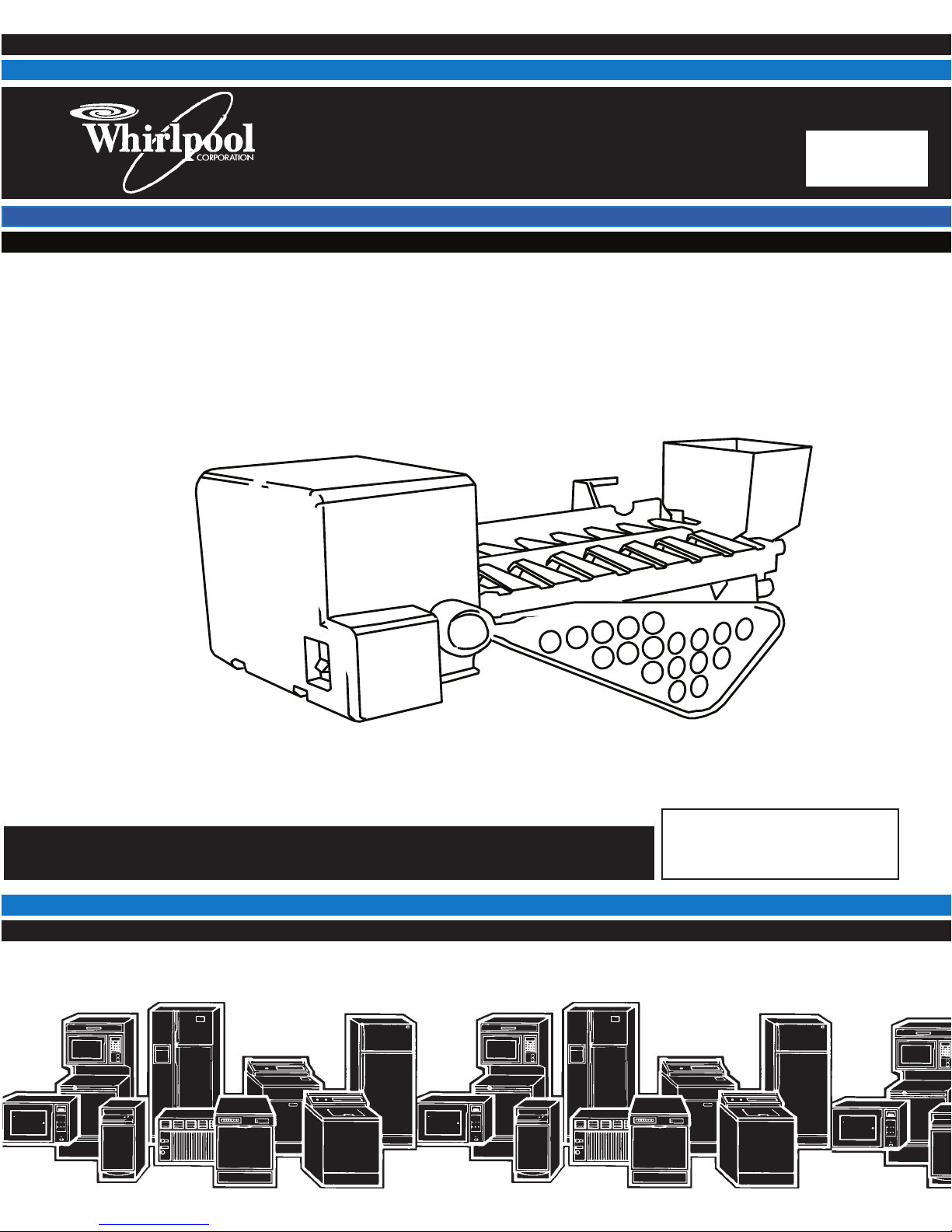
Icemaker Familiarization and Troubleshooting
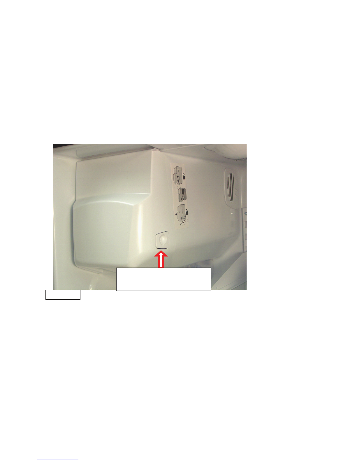
New Generation Compact Ice Maker
French Door Ice2o
To access, depress
release button
Mid-South
Ice Makers
New Generation Compact – AKA, Mid South used on French Door Refrigerators (Iceland) Ice and Water in the Door
Modular Ice Maker – AKA, Whirlpool used on just about everything else
1
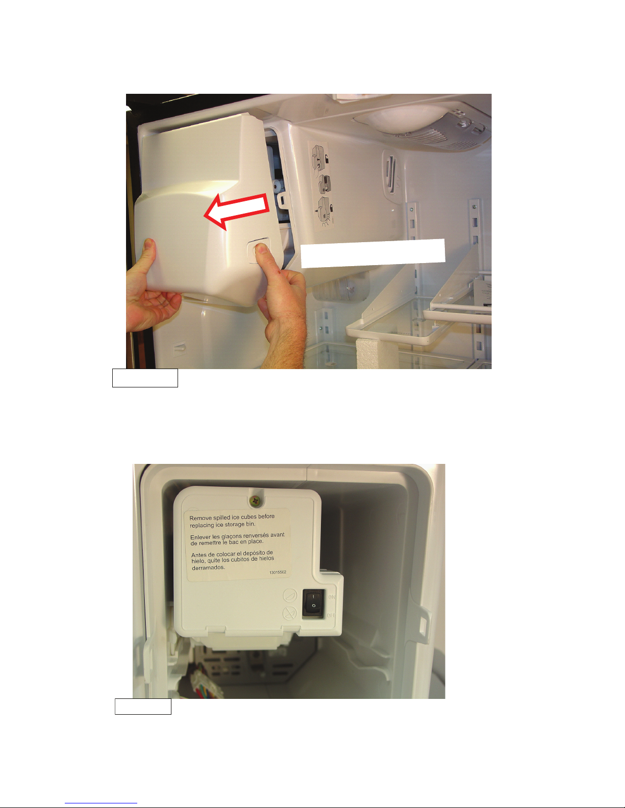
Removing Storage Bin and Cover
Slide Out Bin
Mid-South
To remove storage bin and cover, with the release button depressed slide out the
Bin and Cover Removed
Mid-South
assembly.
With the ice bin removed, the icemaker can be accessed.
2
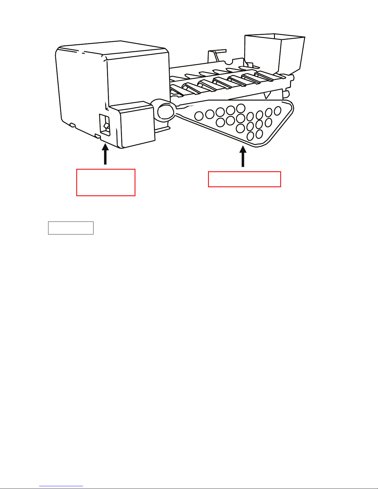
ON/OFF
Switch
Shut-off Arm
Mid-South
Mid-South
Mid South - This compact design is a variation of previous designs. Operation is
identical except for the following:
The metal feeler arm has been replaced with a plastic paddle that moves up and
down on a cam.
During the ice ejection cycle, the paddle lifts in the same manner as the feeler arm
and automatically turns the icemaker off if it senses that the bucket is full (while on its
downward movement).
3
Operation
Operation
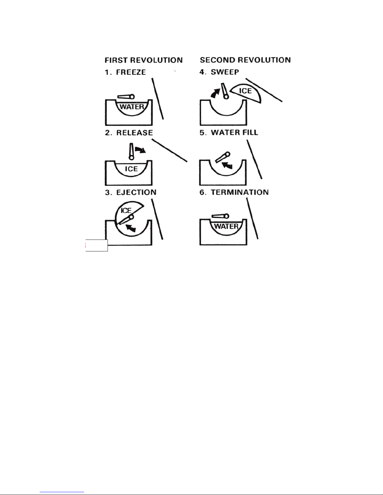
Icemaker Operational Cycle
Both the Compact and the Modular icemakers rely on a combination of electrical and
mechanical functions to create and eject ice. The complete ice cycle for the Compact
icemaker is described below and is divided into six major functions. The Modular icemaker cycle is also divided into the same six functions but requires only one revolution to complete the ejection of the ice. The six major functions are:
Freeze- Water enters the icemaker and is deposited in an ice mold. While the evaporator fan runs, part of the sub zero air that enters the freezer compartment is directed
across the top of the mold. Heat is removed from the water and the water freezes in
the mold.
Release- The temperature of the ice continues to drop until a thermostat in the icemaker closes. The thermostat is in contact with the mold and senses the temperature
of the mold and, thus, the ice within the mold. Designs vary but the mold temperature
must drop to around 15°F before the thermostat closes. This assures that the water
is completely frozen before the icemaker attempts to eject the ice. The closing of the
thermostat energizes a mold heater and starts the icemaker motor. The purpose of
the heater is to raise the temperature of the mold above 32°F.
Eject- With the mold heater energized, the ice in the mold begins to melt, freeing the
ice from the mold. At the same time, the icemaker motor turns an ejector blade which
lifts the ice out of the mold and dumps it into the ice bucket.
Sweep- The icemaker motor continues to rotate the ejector blade for another revolu-
tion. Any ice that might have not ejected during the rst sweep will be ejected.
4

Water ll- At the end of the second revolution, an internal cam in the icemaker ener-
gizes a ll switch. The switch turns on the icemaker water valve and water is allowed
to enter the icemaker.
Terminate- Once lled with water, the icemaker cycle terminates. The icemaker is
now ready to repeat the cycle.
Electrical Operation
Ejector Blade Shut off Arm
Freeze cycle
Immediately after the icemaker lls with water, the freezer air begins to cools the ice
mold. Since the mold and water are essentially at the same temperature, the mold
thermostat will remain open until the ice and mold reach a predetermined temperature
(15°F, ±3°). Notice that the ejector blades are at approximately the 9:00 o’clock position at the start of the cycle. This is known as the “home” position.
Thermostat Closes
When the mold and ice reach the set temperature, the thermostat closes. The mold
heater is energized through a parallel circuit which also energizes the motor.
First Three Seconds of Operation
All the while the icemaker is in the freeze cycle, the hold switch contact sits in a notch
on the icemaker cam. As soon as the motor begins to rotate the cam, the hold switch
contacts transfer and the switch closes. The hold switch contacts remain in this position until the cam has traveled a full 360° and the switch contact falls into the notch
again.
At the same time, the feeler arm begins to raise. Since the shut-off switch is mechanically coupled to the feeler arm, movement of the arm causes the shut-off switch
contacts to transfer. The transfer of both these switches creates a parallel current
path for the mold heater and the icemaker motor. The heater begins to thaw the ice
in the mold and the motor advances the ejector blades until they come in contact with
the ice.
Blade Contacts Ice
Upon contacting the ice, the motor stalls since the mold heater has not had sufcient
time to melt the ice enough to free it from the mold. The heater continues to warm
the mold until the ice is free and the blades can dislodge the ice and continue their
sweep.
Once free of the mold, the ice loosens and the blades resume their rotation towards
the home position (9:00 o’clock). The ice is ejected.
Water Switch Closes
Just before the blades reach their home position, the cam closes the water ll switch
for approximately 7 seconds. Since the thermostat has not yet opened and is shunting the water valve solenoid, the water valve doesn’t open at this time.
Start of the Second Revolution
Once the cam reaches the home position, the hold switch momentarily goes back to
its normally closed position. While the mold has heated sufciently to loosen the ice,
the mold has not yet reached the temperature required to open the mold thermostat.
The motor and heater continue to operate through the closed thermostat.
5

After Three Seconds
(Second Revolution)
Just as before, the cam continues its rotation and the hold switch contacts transfer to
the normally open position. The feeler arm begins to raise. The shut-off switch contacts transfer and the ejector blades resume their sweep.
If the bucket is full, the feeler arm will come to rest on top of the ice and prevent the
shut–off switch from resetting. This will keep the icemaker from producing any more
ice until the customer removes some of the ice from the bucket.
Thermostat Opens
Some time during the second revolution, the mold warms enough to open the thermostat and the heater is taken out of the circuit. The motor continues to get its power
through the normally open contacts of the hold switch.
Water Switch Closes
Just before the cam returns to the home position, the water switch is closed for the
second time. This time, the thermostat is open, eliminating the shunt to the water
valve. The water valve is energized for about 7 seconds. Current path for the valve is
from L1, through the heater and water switch.
Back to the Freeze Cycle
Once the motor advances the cam back to its home position, the hold and shut-off
switches transfer back to their normal positions and the icemaker is now ready for the
next freeze cycle. Once the mold gets down to temperature, the icemaker thermostat
closes and the ice harvest cycle repeats.
Water Fill Adjustment
Many of compact icemakers used today are equipped with a water ll adjustment.
Turning the ll adjustment screw changes the alignment between the cam and switch
and alters the amount of time the ll switch is energized. One full turn of the screw in
either direction changes the ll ±20 cc’s (approximate).
Manual Cycle Initiation
As we learned, the icemaker ejection cycle is initiated by the thermostat. If, however,
the icemaker is not ejecting, it will be necessary to manually initiate an ice ejection
cycle.
After removing the front cover, turn the motor shaft (small gear) ½ turn in the counterclockwise direction. This will rotate the cam enough to transfer the hold switch and
provide power to the motor. If the thermostat is closed at this time, the heater will
likewise be energized and the icemaker will complete the cycle.
After manual initiation, carefully feel the bottom of the mold. It should begin to heat. If
it doesn’t, either the thermostat has not yet closed or the heater is open.
Before manually initiating a cycle, check the position of the ejector arm. Assuming
the problem is in the icemaker, the position of the ejector arm will give you an indication of the failed component.
If the ejector blades are still in the home position (9 o’clock) the thermostat is most
likely at fault.
If the ejector blades stopped between the 9 and 10 o’clock positions, the hold switch
is most likely at fault.
An ejector at the 4 o’clock position normally indicates an open heater.
Any position other than the 9 or 4 o’clock positions may indicate motor problems or
broken, stripped or missing parts in the housing.
6
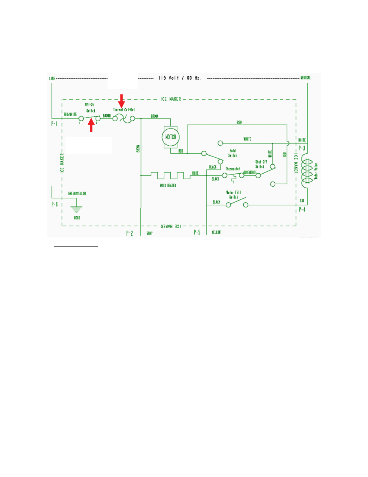
New Generation Schematic
120 Volt 60 Cycles
TCO
(New)
On/Off
Switch (New)
Mid-South
Mid South design incorporates an ON/OFF switch and Thermal Cut out. These features were not on the original Whirlpool compact design.
7
 Loading...