

Whirlpool QCAE2733BQ Installation Instructions

INSTALLATION
INSTRUCTIONS
CommerCial Washer
INSTRUCTIONS
D’INSTALLATION
laveuse CommerCiale
TABLE OF CONTENTS
Page
Washer Safety .......................................................................... 2
Tools & Parts ............................................................................ 3
Dimensions .............................................................................. 4
Location Requirements ...........................................................5
Drain System ............................................................................ 6
Electrical Requirements..........................................................7
Installation Instructions .......................................................... 8
Connect Drain Hose ................................................................ 9
Connect Inlet Hoses .............................................................. 10
Level Washer ..........................................................................11
Installing Coin Slide and Coin Box ....................................... 11
Complete Installation ............................................................ 12
Typical Full Load Sizes .......................................................... 12
Washer Maintenance.............................................................13
If You Need Assistance ......................................................... 14
Alternate Parts ....................................................................... 14
TABLE DES MATIÈRES
Page
Sécurité de la laveuse ........................................................... 15
Outillage et pièces ................................................................. 16
Dimensions ............................................................................ 17
Exigences d’emplacement ................................................... 18
Système de vidange .............................................................. 19
Spécications électriques .................................................... 20
Instructions d’installation ..................................................... 21
Raccordement du tuyau de vidange .................................... 22
Raccordement des tuyaux d’arrivée d’eau ......................... 23
Établissement de l’aplomb de la laveuse ............................ 24
Installation de la glissière et de la boîte à monnaie ........... 24
Achever l’installation ............................................................. 25
Taille typique des charges complètes ................................. 25
Entretien de la laveuse .......................................................... 26
Si vous avez besoin d’assistance ........................................ 27
Autres pièces ......................................................................... 27
W10474263E
W10474279E – SP
www.whirlpoolcommerciallaundry.com
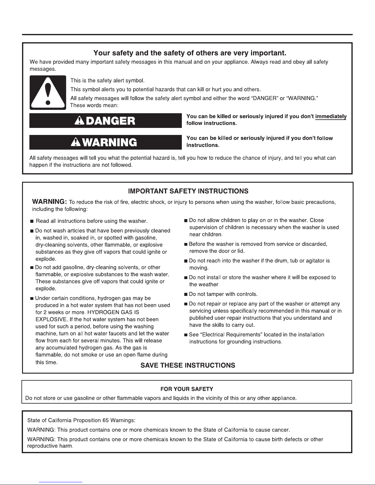
WASHER SAFETY
2
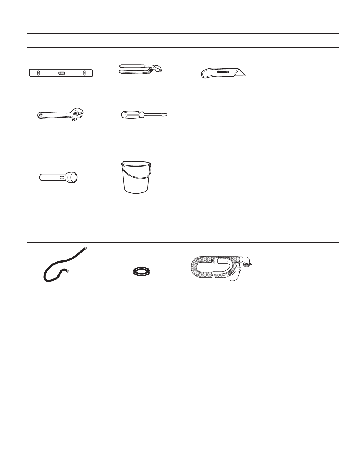
Tools Needed:
Level Pliers Utility Knife
Adjustable Wrench Flat-Blade Screwdriver
Optional tools:
TOOLS & PARTS
Flashlight Bucket
Parts Supplied:
Water Inlet Hoses (2) Inlet Hose Washers (4)
Drain hose with clamp,
U-form, and cable tie
3
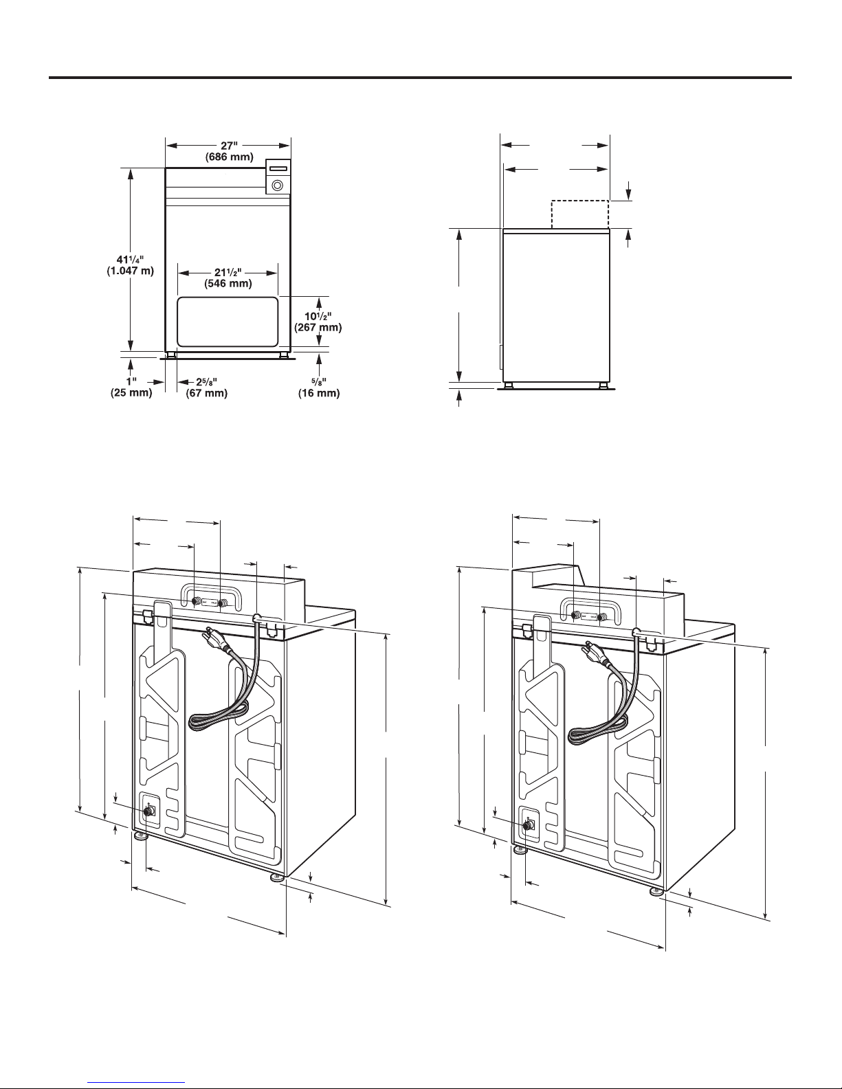
DIMENSIONS
Front View Side View
271/2"
(699 mm)
27"
(686 mm)
35"
(889 mm)
1"
NOTE: Service panel not included on some models.
(25 mm)
Non-coin-operated
models:
1
6
/4"
(159 mm)
Coin-operated
models:
81/4"
(210 mm)
Back View
Non-coin operated models Coin operated models
16"
(406 mm)
101/2"
(267 mm)
41/4"
(108 mm)
411/4"
(1.047 m)
(914 mm)
61/2"
(165 mm)
36"
16"
(406 mm)
101/2"
(267 mm)
41/4"
(108 mm)
(686 mm)
27"
51/2"
(140 mm)
1"
(25 mm)
351/2"
(902 mm)
431/4"
(1.098 m)
36"
(914 mm)
61/2"
(165 mm)
27"
(686 mm)
51/2"
(140 mm)
351/2"
(902 mm)
1"
(25 mm)
4
LOCATION REQUIREMENTS
Selecting the proper location for your washer improves
performance and minimizes noise and possible washer “walk.”
Your washer can be installed in a basement, laundry room, or
recessed area. See “Drain System.”
Companion appliance location requirements should also be
considered.
IMPORTANT: Do not install or store the washer where it will be
exposed to the weather. Do not store or operate the washer in
temperatures at or below 32°F (0°C). Some water can remain in
the washer and can cause damage in low temperatures. Proper
installation is your responsibility.
You will need:
n A water heater set to 120°F (49°C).
n A grounded electrical outlet located within 4 ft. (1.2 m) of
power cord on back of washer. See “Electrical Requirements.”
n Hot and cold water faucets located within 4 ft. (1.2 m) of hot
and cold water ll valves on washer, and water pressure
of 20-100 psi (138-690 kPa). A pressure reduction valve
should be used in the supply line where inlet pressure
entering the building exceeds 100 PSI (690 kPa) to avoid
damage to the washer mixing valve.
n Single washer installations require 12" (300 mm) minimum
risers to provide an air cushion and avoid noise and damage
to valves.
n A level oor with maximum slope of 1" (25 mm) under entire
washer. Installing on carpet is not recommended.
n
Floor must support washer’s total weight (with water and load)
of 315 lbs (143 kgs).
n A oor drain under the bulkhead. Prefabricated bulkheads
with electrical outlets, water inlet lines, and drain facilities
should be used only where local codes permit.
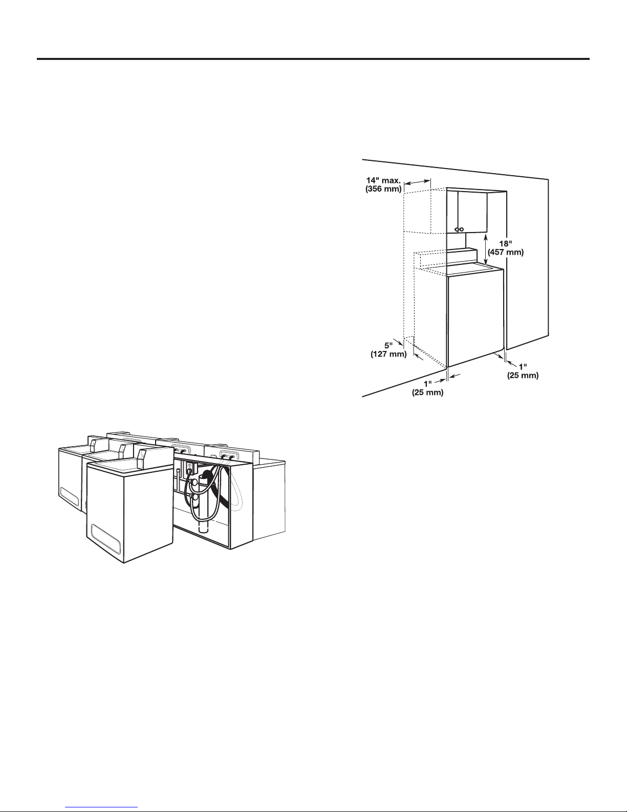
Recessed Area or Closet Installation
This washer may be installed in a recessed area or closet.
The installation dimensions shown are the minimum spaces
allowable. Additional spacing should be considered for ease of
installation and servicing. Companion appliance spacing should
be considered.
Minimum installation spacing
5
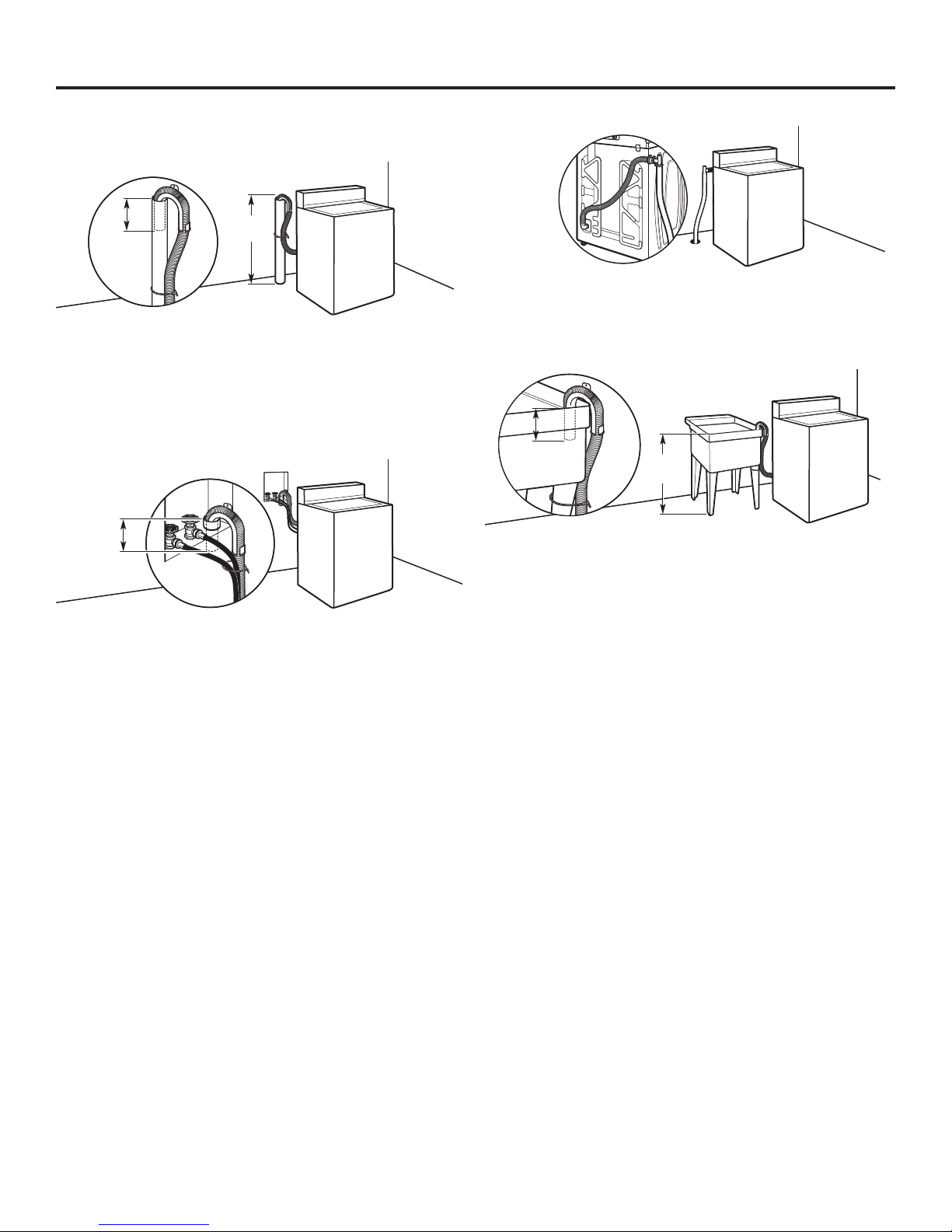
DRAIN SYSTEM
4.5"
(114 mm)
Drain system can be installed using a oor drain, wall standpipe,
oor standpipe, or laundry tub. Select method you need.
Floor standpipe drain system
39"
4.5"
(114 mm)
Minimum diameter for a standpipe drain: 2" (51 mm). Minimum
carry-away capacity: 10 gal. (38 L) per minute. Top of standpipe
must be at least 39" (990 mm) high; install no higher than
96" (2.44 m) from bottom of washer.
(990 mm)
Wall standpipe drain system
4.5"
(114 mm)
Floor drain system
Floor drain system requires a Siphon Break Kit (Part Number
285834). Minimum siphon break: 28" (710 mm) from bottom
of washer. Additional hoses may be needed.
Laundry tub drain system
39"
(990 mm)
Minimum capacity: 20 gal. (76 L). The top of the laundry tub
must be at least 39" (990 mm) above oor.
See requirements for oor standpipe drain system.
6
WARNING
Electrical Shock Hazard
Plug into a grounded 3 prong outlet.
Do not remove ground prong.
Do not use an adapter.
Do not use an extension cord.
Failure to follow these instructions can result in death,
re, or electrical shock.
n
A 120 volt, 60 Hz., AC only, 15- or 20-amp, fused electrical supply
is required. A time-delay fuse or circuit breaker is recommended.
It is recommended that a separate circuit breaker serving only
this appliance be provided.
n
This washer is equipped with a power supply cord having
a 3 prong grounding plug.
n
To minimize possible shock hazard, the cord must be plugged
into a mating, 3 prong, grounding-type outlet, grounded in
accordance with local codes and ordinances. If a mating outlet
is not available, it is the personal responsibility and obligation
of the customer to have the properly grounded outlet installed
by a qualied electrician.
n
If codes permit and a separate ground wire is used, it is
recommended that a qualied electrician determine that
the ground path is adequate.
n
Do not ground to a gas pipe.
n
Check with a qualied electrician if you are not sure the
washer is properly grounded.
n
Do not have a fuse in the neutral or ground circuit.
ELECTRICAL REQUIREMENTS
7
INSTALLATION INSTRUCTIONS
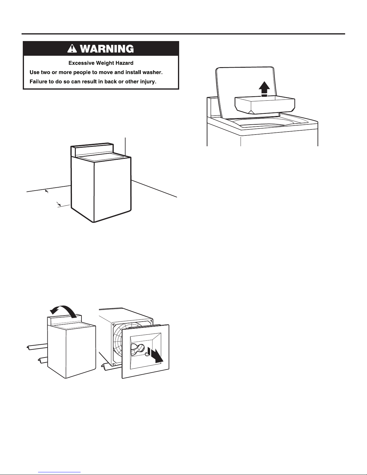
3. Remove tape from washer lid, open lid, and remove cardboard
packing tray from tub. Be sure to remove all parts from tray.
NOTE: Keep tray in case you need to move washer later.
It is necessary to remove all shipping materials for proper
operation and to avoid excessive noise from washer.
1. Move washer to within 4 ft (1.2 m) of its nal location; it must
be in a fully upright position.
NOTE: To avoid oor damage, set washer onto cardboard
before moving it and make sure lid is taped shut.
48"
(1.2 m)
2. To avoid damaging oor, place cardboard supports from
shipping carton on oor behind washer. Tip washer back
and place on cardboard supports. Remove shipping base.
Set washer upright.
IMPORTANT: Removing shipping base is necessary for proper
operation. If your washer includes a sound shield, please refer
to the instructions included with the sound shield to install it
at this time.
NOTE: Keep shipping base in case you need to move washer
later.
8
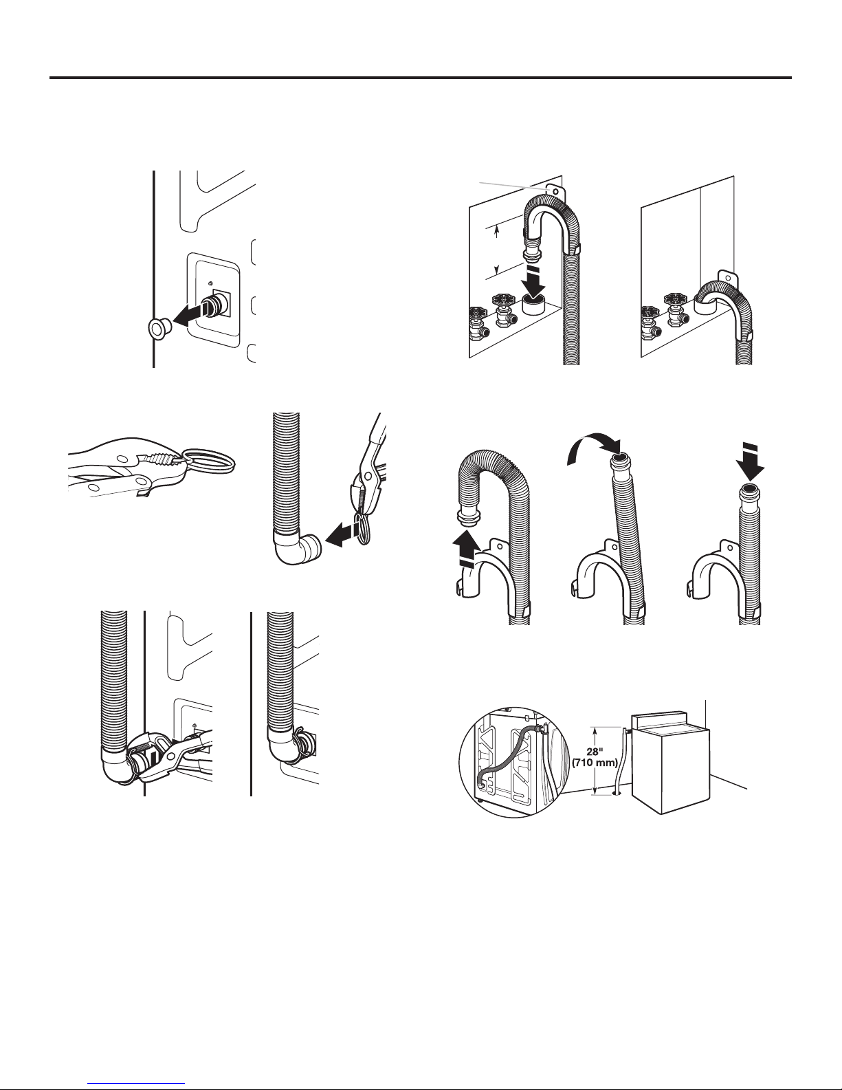
CONNECT DRAIN HOSE
Proper routing of the drain hose avoids damage to your oor
due to water leakage.
Remove drain hose from the washer drum
1. Remove tape from the washer drain port on the back of
the washer.
2. If clamp is not already in place on elbow end of drain hose,
slide it over end as shown.
5. Place hose into standpipe (shown in picture) or over side
of laundry tub.
IMPORTANT: 4.5" (114 mm) of drain hose should be inside
standpipe; do not force excess hose into standpipe or lay
on bottom of laundry tub. Drain hose form must be used.
Drain
hose form
4.5"
(114 mm)
6. For oor drain installations, you will need to remove the drain
hose form from the end of the drain hose. You may need
additional parts with separate directions. See “Tools and Parts.”
3. Squeeze clamp with pliers and slide elbow end of drain
hose onto washer drain port and secure with clamp.
4. The washer drain system can be installed using a oor drain,
wall standpipe, oor standpipe, or laundry tub.
7. The oor drain system requires a siphon break that may be
purchased separately. The siphon break (Part Number 285834)
must be a minimum of 28" (710 mm) from the bottom of the
washer. Additional hoses might be needed.
9
 Loading...