

Whirlpool NWF0600, NWF0601, NWF0602, NWF2900, NWF2901 Installation, Use & Care
...
No. Parte W10216838 Rev. C
stm02601 Rev. C
NWF0600
NWF0601
NWF0602
NWF2900
NWF2901
NWF5900
Ampara los
siguiente
Modelos:
Índice..........................................2
Este manual contiene información útil, léalo
detenidamente antes de poner a funcionar
su estufa.
Cover
the following
models:
Index......................................2
This guide contains useful information,
read it carefully.
Manual
NWF0600
NWF0601
NWF0602
NWF2900
NWF2901
NWF5900
Part No. W10216838 Rev. Cstm02601 Rev. C
Partes y Características
2
Parts and Features
2
FABRICADO POR:
INDUSTRIAS ACROS WHIRLPOOL, S,A, DE C.V. Unidad Celaya
km 280
CARRETERA PANAMERICANA C.P. 38020, CELAYA, GTO.
Tel. 01(461)6185500
MANUFACTURED BY:
INDUSTRIAS ACROS WHIRLPOOL, S,A, DE C.V. Unidad Celaya
km 280
CARRETERA PANAMERICANA C.P. 38020, CELAYA, GTO.
Tel. 01(461)6185500
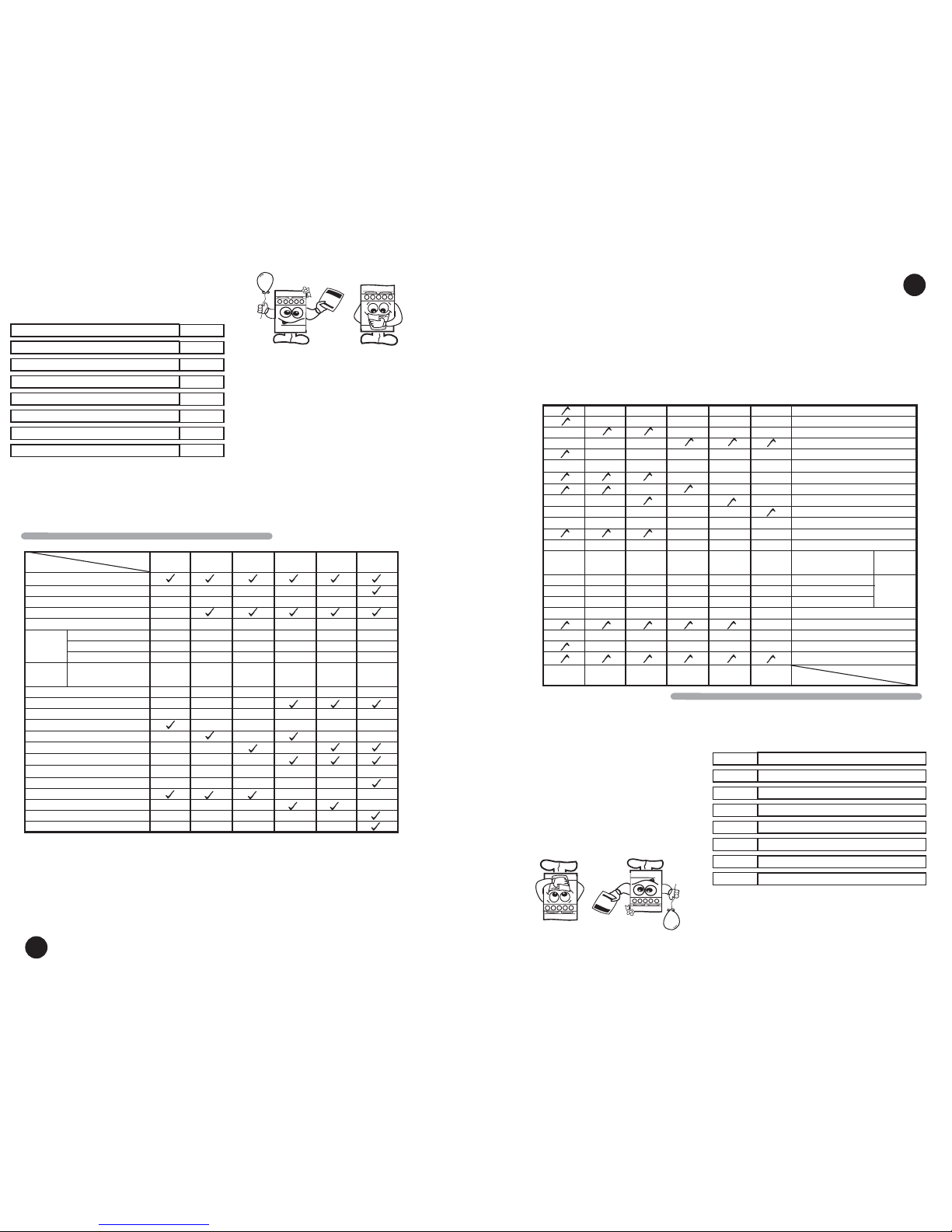
Modelo
Características
NWF0600
Manual
3
Porcelanizada
Manual
NWF0601
3
Porcelanizada
2
NWF0602 NWF2900 NWF2901 NWF5900
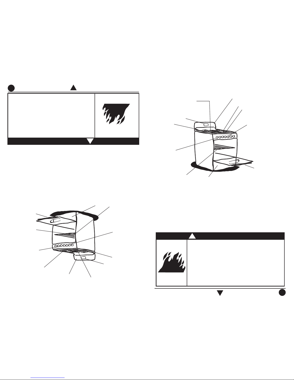
Respaldo Superior
Reloj
Parrillas Superiores
Comal de Sobreponer
Cubierta
Quemador
Estampado
Encendido Quemadores Superiores
Perilla de Seguridad
Encedido Horno
Termocontrol
Termocontrol 5 pasos
Termostato simple
Luz de horno
Parrilla de horno
Parrillas Deslizables
Ventana de Horno Estandar
Ventana de Horno Extra Larga
Quemador
de Aluminio
Ventana de Horno Panoramica
Asador
2
1
66666
Manual Manual Elect. Elect. Elect.
1
2
Manual
3
Porcelanizada
2
3
Porcelanizada
2
Manual
3
Porcelanizada
2
3
Porcelanizada
Quemador tamaño Estandar
Superquemador
Quemador alargado
Quemador tamaño
Estandar con Tapa
de Laton
Thermocontrol 5 Steps
Upper Burners Ignition
Backguard
Model
Characteristics
NWF0600
Manual
3
Porcelanized
Manual
NWF0601
3
2
NWF0602 NWF2900 NWF2901 NWF5900
Clock
Top Grates
Over Grate Griddle
Cooktop
Stamped
Burner
Safe Knobs
Oven Ignition
Thermocontrol
Simple thermostat
Oven light
Oven Racks
Slide out Oven Rack
Standard Window
Extra Large Window
Aluminum
Burner
Panoramic Door
Broiler
2
1
66666
Manual Manual Electric Electric Electric.
1
2
Manual
3
2
3
2
Manual
3
2
3
Standard Burner
Super Burner
Five Burner
Standard Burner with
Brass Cap
Porcelanized Porcelanized Porcelanized Porcelanized Porcelanized
Acaba de adquirir un producto desarrollado
con las más avanzadas técnicas de diseño
y fabricación.
Le sugerimos que antes de usar su estufa
lea cuidadosamente las instrucciones de
este manual. Consérvelo ya que la
información contenida en el mismo será
importante para el buen funcionamiento de
su estufa durante muchos años.
Partes y Características
Instalación
Conexión
Funcionamiento
Limpieza
Póliza de Garantía
Formato de Identificación
Servicio
2
4
4
5
12
14
14
15
Índice
Parts and Features
Installation
Gas Supply Connection
How to Use Your Range
Cleaning and Maintenance
Warranty
Identification Format
Service
2
4
4
5
12
14
14
15
¡ Congratulations !
This range was carefully manufactured with
the latest technical expertise. By purchasing
it, you have received quality.
Before you use your range, read the
instructions in this manual. The information
is important for best results in the use of
your range.
Index
Manual ManualManual
ManualManualManual
3
Instale su estufa en un lugar protegido de las inclemencias del tiempo y sobre una
superficie plana y resistente para soportar su peso.
No permita que la usen niños o personas que no conozcan su funcionamiento.
Proporciónele el mantenimiento adecuado.
Utilice la estufa sólo en labores del hogar. No es un aparato de uso comercial.
Quemadores Superiores
Peligro de Incendio y/o Quemaduras
No permita que los niños usen o jueguen con la estufa;
manténgalos alejados mientras está en uso.
Mantenga los alrededores del aparato libres de materiales
combustibles, gasolina y otros vapores o líquidos flamables.
No se acerque demasiado a las flamas de los quemadores, ni
use ropa suelta, ya que se puede encender y causar quemaduras.
No use su estufa para calentar habitaciones, ya que esto es
peligroso.
No seguir estas instrucciones puede ocasionar incendio,
quemaduras o la muerte.
ADVERTENCIA
!
3
Install your range in an area that is protected against weather exposure, on a level floor
strong enough to sustain its weight.
Do not allow range to be used by children or unqualified adults.
Provide for adequate maintenance.
Use the range only in home applications. It is not designed for commercial use.
Parrillas Superiores
Parrilla de
Horno
Fire or Explosion Hazard
Do not allow children to use or play with the range;
keep children away while range is in use.
Keep the range surroundings free of flammable material,
gasoline and other vapors or flammable liquids.
Do not get too close to the flame produced by the
burners or wear loose clothing; your clothes may ignite
if contact by open flames.
Do not use your range to warm rooms, because this is
dangerous.
Failure to do so can result in death, fire or explosion.
WARNING
!
Termocontrol o
Termocontrol de 5 pasos
Termostato simple
(ver tabla pag. 2)
Asador
Perilla
Comal de sobreponer
Puerta de Horno
Thermocontrol or
Thermocontrol 5 steps
Simple Thermostat
see table page 2
Oven Grates
Broiler
Over Grate Griddle
Oven Door
Oven Rack
Top Burners
Knobs
Respaldo Superior
Cubierta
Cooktop
Backguard
Clock
Reloj
4
4
Installation
61 cm
min.
Proper installation is your responsibility. A qualified
technician or Service technician must install this
range.
Remove all packing material and put the range
accessories in their places.
Select the best location in your kitchen for your
range. Protected from wind and
with enough space
to open the oven door.
Do not install cabinetry directly above the range.
If you will install an exhaust device, put it at 61 cm
minimum from the range cooktop.
If your range has a power cord it must be installed
near an electrical wall outlet.
Do not use extension cords or multiple outlets.
Instalación
La instalación apropiada es su responsabilidad.
Un técnico calificado o un técnico de Servicio debe
instalar esta estufa.
Retire los elementos de empaque y coloque los accesorios
de la estufa.
Seleccione la mejor ubicación para su estufa. No debe
quedar expuesta a corrientes de aire y debe tener espacio
suficiente para abrir la puerta del horno.
No instale gabinetes o
muebles de cocina encima de la
estufa.
Si instala campana extractora,
colóquela a 61 cm como
mínimo de la cubierta de la estufa.
Si su estufa cuenta con accesorios eléctricos colóquela
cerca de un tomacorriente de pared.
No use extensiones eléctricas o contactos múltiples.
61 cm
mínimo
CAMPANA EXTRACTO
RA
EXHAUST DEVICE
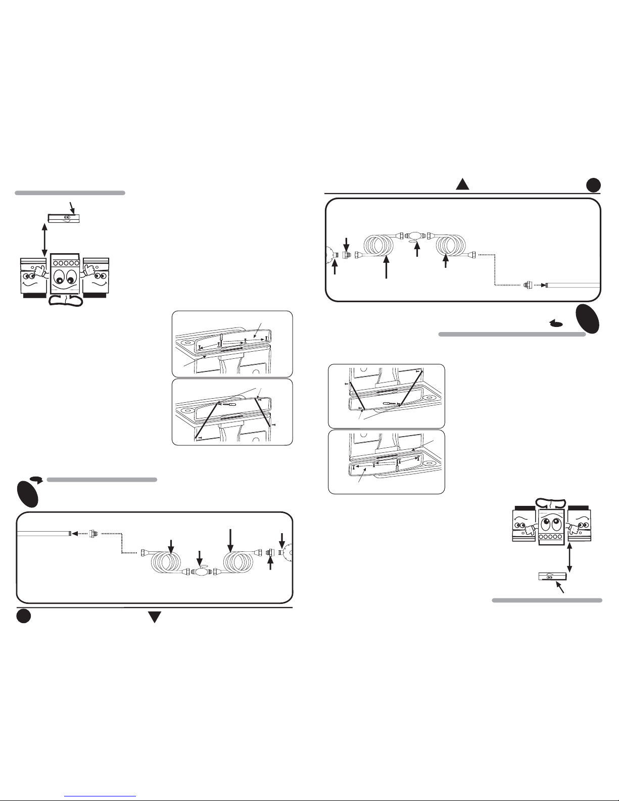
Conexión
CONEXIÓN DE LA ESTUFA A LA LÍNEA DE GAS
Para conectar su estufa, utilice el material especificado
en la figura de abajo.
1
Gas Supply Connection
GAS SUPPLY CONNECTION
To connect the range, use the material shown in the bottom figure.
1
NOTA: El m
aterial m
ostrado para instalacion no
viene con la estufa.
Tubo de Alim
entación
integrado a la estufa
Llave de paso
de 9,5 m
m (3/8")
Cople-Niple de 9,5 m
m (3/8"NPT)
a 9,5 m
m(3/8")cónica
Tubo de cobre con tuercas
cónicas de 9,5 m
m (3/8")
Tubo de cobre con tuercas
cónicas de 9,5 m
m (3/8") de
longitud necesaria para llegar
al gas
Cople-Niple de
9,5 mm (3/8"NPT)
Regulador
de gas
NOTA: Su estufa puede estar equipada de fábrica con:
1.- Tubo de Alim
entacion ó
2.- Válvula de Corte de G
as.
NOTE: The range could be equipped from
the factory with
one of the following accesories:
1.- Gas Inlet Tube Fitting or
2.- Shut Off Gas Valve.
3/8" shut off
valve
Gas Inlet Tube Fitting
integrated to the range
3/8" NPT to 3/8" brass pipe
fitting Hex. adapter
3/8" copper pipe
with 5/8" flared
type nut
Gas
regulator
3/8" copper pipe with
5/8" flared type nut.
Necessary
length to reach the
gas
3/8" brass pipe
fitting
Hex. adapter
NOTE: The m
aterial shown for installation
is not provided with the range.
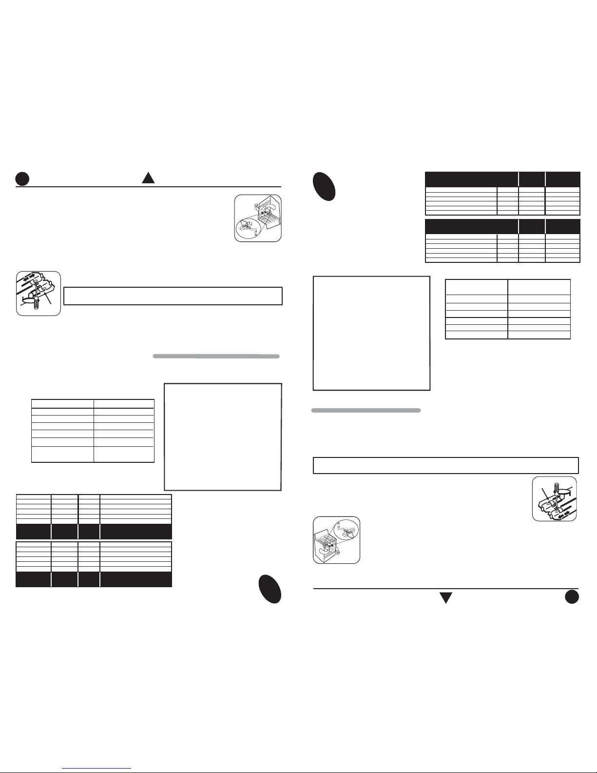
How to Install the backguard in ranges
1.-Backguard parts are inside oven (Backguard,
rear supports, screws, washers, installation
instructions)
2.-Mount the backguard in place over the cooktop
(see figure 1)
3.-Use the screws and the washers to fix the
backguard to the range.
4.-Check that the backguard is property fixed.
5.- Assemble the rear supports as seen in figure 2.
Como instalar el respaldo superior
1.-Las partes del respaldo superior se encuentran
en el horno (respaldo, travesaños, tornillos,
roldanas, instrucciones de instalación)
2.-Coloque el respaldo sobre la cubierta (ver
figura 1).
3.-Utilizando los tornillos y las roldanas, atornille
el respaldo a la estufa.
4.-Verifique que el respaldo quede fijo.
5.- Coloque los travesaños como se muestra en
la figura 2.
Figura 1
RESPALDO
SUPERIO
R
BACKG
UARD
CUBIERTA
COOKTOP
TRAVESAÑO
S
Figura 2
REAR SUPPO
RTS
Figure 2
Figure 1
BACKG
UARD
COOKTOP
5
5
Con el fin de facilitar el movimiento del
aparato, el instalador debe hacer una
espiral con el tubo flexible de cobre e
instalar una llave de paso en la línea
de suministro de gas. Esta llave debe
estar fuera de la estufa y accesible a
las personas que la usan.
Si la instalación no es nueva, limpie los
tubos de cobre, para evitar que se tapen
las espreas y/o pilotos.
IMPORTANTE
Esta estufa está preparada para
funcionar con gas L.P. de tanque
móvil o estacionario.
Para usarse con gas natural ( de
tubería) debe llamar a Whirlpool
Service para cambiar las espreas
y hacer los ajustes necesarios. El
número telefónico aparece en la
página 15. El técnico calificado
debe cerciorarse que la conexión
no tiene fugas y que la presión de
gas en la estufa es la que aparece
en las tablas.
NOTA: Para operar esta estufa con gas natural, se requiere
el juego de conversión de acuerdo con la siguiente tabla:
Este juego está disponible en Whirlpool Service
IMPORTANT
To make it easier to move the
appliance, the installer should loop the
3/8" copper tubing as shown in the
illustration.
If the installation is not new, you should
clean it in order to avoid the obstruction
of orifices and/or pilots.
This range is adjusted at the factory
for use with L.P. gas.
To use this range with natural gas,
you must replace the surface and
oven burner orifices, call Whirlpool
Service. The phone number
is shown in the page 15. The
technician must make sure that the
connections have no leaks and the
gas pressure in the range is the
same as shown in the charts.
NOTE: To operate this range with natural gas,
is required a kit according to the chart:
This kit is available at your nearest Whirlpool
Service.
2
Cheque con agua jabonosa
que no existan fugas.
2
Check with soap solution for leaks.
GAS LP PRESIÓN DE OPERACIÓN
2,75 kPa (28 cm Col. agua)
QUEMADOR
SUPERIOR STD. EST
AMPADO
SUPERIOR SUPER ESTAMPADO
SUPERIOR CENTRAL ESTAMPADO
SUPERIOR STD. ALUMINIO
HORNO
ESPREA
69
66
69
78
57
mm
0,741
0,838
0,741
0,78
1,092
kJ/h
6 800
7 500
6 800
7 000
13 600
DIAM.
ESPREA
CAPACIDAD
TERMICA
ESPREA
58
57
58
115
53
mm
1,06
1,09
1,06
1,15
1,511
kJ/h
6 800
7 500
6 800
7 000
13 600
DIAM.
ESPREA
CAPACIDAD
TERMICA
GAS NATURAL PRESIÓN DE OPERACIÓN
1,76 kPa (18 cm Col. agua)
QUEMADOR
SUPERIOR STD. ESTAMPADO
SUPERIOR SUPER ESTAMPADO
SUPERIOR CENTRAL ESTAMPADO
SUPERIOR STD. ALUMINIO
HORNO
Gas LP a
Modelo Gas Natural
NWF0600
NWF0601
NWF0602
NWF2900
NWF2901
NWF5900
W10132617
W10158283
W10217319
W10158283
W10217319
W10217319
Funcionamiento
How to Use Your Range
NUMBER
69
66
69
78
57
LP GAS OPERATING PRESSURE
11 in WATER COLUMN
(6,36 oz/squared inch)
BURNER
UPPER STD STAMPED
UPPER SUPER STAMPED
CENTRAL STAMPED
UPPER STD ALUM.
OVEN
INCHES
.029
.033
.029
.307
.043
BTU/h
6 500
7 100
6 500
6 700
13 000
ORIFICE
DIAMETER
THERMAL
CAPACITY
ORIFICE
NATURAL GAS OPERATING
PRESSURE 7 in WATER COLUMN
(4,04 oz/squared inch)
BURNER
UPPER STD STAMPED
UPPER SUPER STAMPED
CENTRAL STAMPED
UPPER STD ALUM.
OVEN
NUMBER
58
57
58
115
53
INCHES
.042
.043
.042
.045
.059
ORIFICE
DIAMETER
THERMAL
CAPACITY
ORIFICE
BTU/h
6 500
7 100
6 500
6 700
13 000
LP Gas a
Model Natural Gas
NWF0600
NWF0601
NWF0602
NWF2900
NWF2901
NWF5900
W10132617
W10158283
W10217319
W10158283
W10217319
W10217319
HOW TO ADJUST THE FLAMES
NOTE: Adjustment for top burners only apply for Models with Stamped
Burners (see page 2 ), for aluminium burners not apply
Air Regulator
AJUSTE DE FLAMAS
Las diferentes altitudes sobre el nivel del mar y las variaciones en el suministro de gas, hacen
necesario regular la entrada de aire primario a los quemadores para obtener una adecuada
mezcla de aire-gas y así obtener un buen funcionamiento en la estufa. Revise que las flamas
de los quemadores superiores y del horno sean estables y azuladas, de no ser así siga los
pasos para su ajuste.
Ajuste de quemadores superiores estampados
1.Retire las perillas.
2.Retire los tornillos que sujetan de abajo el frente de perillas y los tornillos
que sujetan el travesaño a los laterales en la parte posterior. (ver figura 1).
NOTA: El
ajuste de quemadores superiores solo aplica a los modelos con quemadores
estampados (ver Pág.2). Para los quemadores de aluminio no es necesario hacerlo.
REGULADOR
DE AIRE
3.Levante un poco el ensamble de la cubierta-frente perillas de la parte posterior,
jale hacia delante y levántelo tratando de evitar jalar los arnesesque vienen
fijos a la cubierta y al frente de perillas. Posiciónelo sobre los laterales de la
estufa (ver figura 2).
4.-Realice el ajuste dependiendo del tipo de quemador con el que cuente su
estufa.
a) Super quemador estampado y quemador estándar estampado
Afloje el tornillo del regulador de aire y abra o cierre la ventana (si la flama es amarilla, abra la
ventana; si la flama es inestable y separada del quemador, cierre la ventana).
Because of different altitudes above sea level and variations in the supply of gas, you may
need to adjust the main air intake to the oven burner. This will result in a better air-gas
mixture and thus.
Check oven burner and Top Burners for proper flame, flame must be stead and blue if not,
follow instructions for flame adjustment.
Top Burners Adjustment for Stamped Burners
1.- Remove knobs.
2.- Unscrew the screw below the manifold panel and the screws that support post to the
laterals at rear side (see fig. 1) and remove it.
3.-Unscrew the screw below, back and the top the cooktop and remove it(See fig. 2)
4.-Carry the adjustment of the burner according the kind of burner your range have.
a) S
tamped Standard Burner and Super Stamped Burner
Adjust air by loosing air shutter screw and turn air shutter to open or close
opening
(if flame is yellow, open burner opening; if flame is blowing, close
opening)
b) Five Burner
Displace the regulator in order to open or close opening (if flame is
yellow
, open burner opening; if flame is blowing close opening.
 Loading...