

Whirlpool LMA1053LQ, LMA1053LT Installation Instructions
DRYING CABINET INSTALLATION INSTRUCTIONS
INSTRUCTIONS D’INSTALLATION DE
L’ARMOIRE SÉCHEUSE
Table of Contents Table des matières
DRYING CABINET SAFETY...........................................................1
INSTALLATION INSTRUCTIONS..................................................2
Tools and Parts ............................................................................2
Location Requirements................................................................2
Electrical Requirements ...............................................................3
Venting Requirements..................................................................4
Unpack Drying Cabinet................................................................5
Install and Level Drying Cabinet ..................................................5
Connect Vent................................................................................6
Reverse Door Swing ....................................................................6
Install Door Slider Kit....................................................................7
Complete Installation ...................................................................8
®
SÉCURITÉ DE L’ARMOIRE SÉCHEUSE ......................................9
INSTRUCTIONS D'INSTALLATION...............................................9
Outillage et pièces........................................................................9
Emplacement d'installation........................................................10
Spécifications électriques ..........................................................11
Exigences du système d'évacuation d’air.................................12
Déballage de l'armoire sécheuse...............................................12
Installation et mise d'aplomb de l'armoire.................................13
Raccordement au conduit d'évacuation....................................14
Inversion du sens d'ouverture de la porte .................................14
Installation des coulisseaux et tringles ......................................15
Achever l'installation ..................................................................16
DRYING CABINET SAFETY
Your safety and the safety of others are very important.
We have provided many important safety messages in this manual and on your appliance. Always read and obey all
safety messages.
This is the safety alert symbol.
This symbol alerts you to potential hazards that can kill or hurt you and others.
All safety messages will follow the safety alert symbol and either the word “DANGER” or
“WARNING.” These words mean:
You can be killed or seriously injured if you don't
immediately follow instructions.
can be killed or seriously injured if you don't
You
follow instructions.
All safety messages will tell you what the potential hazard is, tell you how to reduce the chance of injury, and tell you
what can
happen if the instructions are not followed.
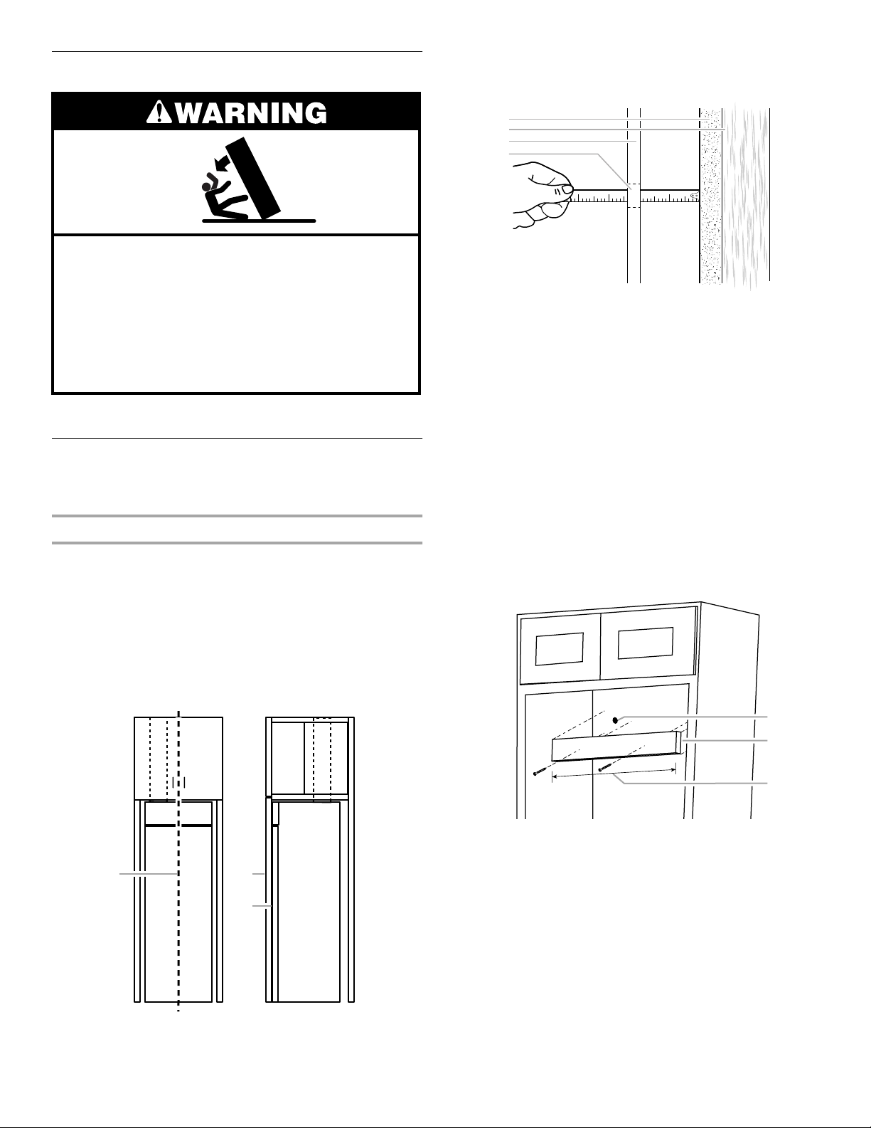
8537102B
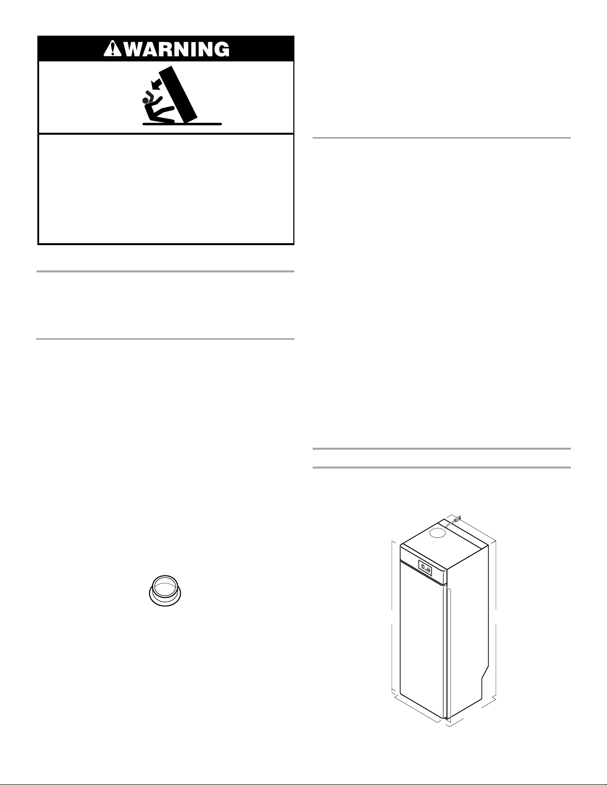
Tip Over Hazard
Drying cabinet is top heavy and tips easily when
not completely installed.
Use two or more people to move and install
drying cabinet.
Failure to do so can result in serious injury
or cuts.
INSTALLATION
INSTRUCTIONS
Tools and Parts
Assemble the required tools and parts before starting installation.
Read and follow the instructions provided with any tools listed
here.
Too ls n eeded
■ Torpedo or pocket level
■ Tape measure
■ Drill (electric recommended)
■ Phillips screwdriver
■ ⁹⁄₃₂ in. drill bit (wall anchor)
Parts supplied
■ Allen wrench
■ Screws (2)
■ Plastic hole plugs (4)
■ ⁷⁄₆₄ in. drill bit (pilot hole)
■ ¹⁄₈ in. drill bit (attaching to
shim)
■ Marker or pencil
■ Gloves (optional)
■ Door Trim Kits (1)
■ Washers (2)
Alternate parts you may need
■ Shim
■ Panel trim kit (part numbers
4396494-white, 4396499biscuit)
Check local codes. Check existing electrical supply and venting.
See “Electrical Requirements” and “Venting Requirements”
before purchasing parts.
■ Screws for securing shim
Location Requirements
You will need
■ A location that allows for proper exhaust installation. See
“Venting Requirements.”
■ A separate 15 or 20 amp circuit.
■ A grounded electrical outlet located within 5 ft. (152.4 cm) of
the drying cabinet. The drying cabinet has a 5 ft. (152.4 cm)
cord located on the top of the cabinet. Locate the power
outlet close enough to the top of the drying cabinet for the
plug to reach the outlet without using an extension cord. The
outlet should be easily accessible after the drying cabinet
installation. Adjust the outlet location if the drying cabinet is
installed inside custom cabinetry. See “Electrical
Requirements.”
■ A sturdy floor to support the total drying cabinet weight of
123 lbs (55.8 kg).
■ A level floor with a maximum slope of 1 in. (2.5 cm) under the
entire drying cabinet.
■ Ceiling must be a minimum of 12 in. (30.5 cm) from the top of
the cabinetry (see “Installation clearances”) or from the top of
the heavy metal vent if not installed in cabinetry.
■ The drying cabinet is designed for operation indoors in a dry
environment at a temperature above 32ºF (0ºC).
■ Check code requirements. Contact your local building
inspector.
Installation clearances
The location must be large enough to allow the drying cabinet
door to be opened fully.
Drying Cabinet Dimensions
23.4"
(59.4 cm)
Hole plug
Parts needed
■ 4 in. (10.2 cm) heavy metal
exhaust vent (3 ft. [91.4 cm]
maximum length)
■ Handle for door trim
2
67"
(170.2 cm)
1"
(2.5 cm)
(door only)
23.4"
(58.4 cm)
60.25"
(153 cm)
24"
(61 cm)
68"
(172.7 cm)
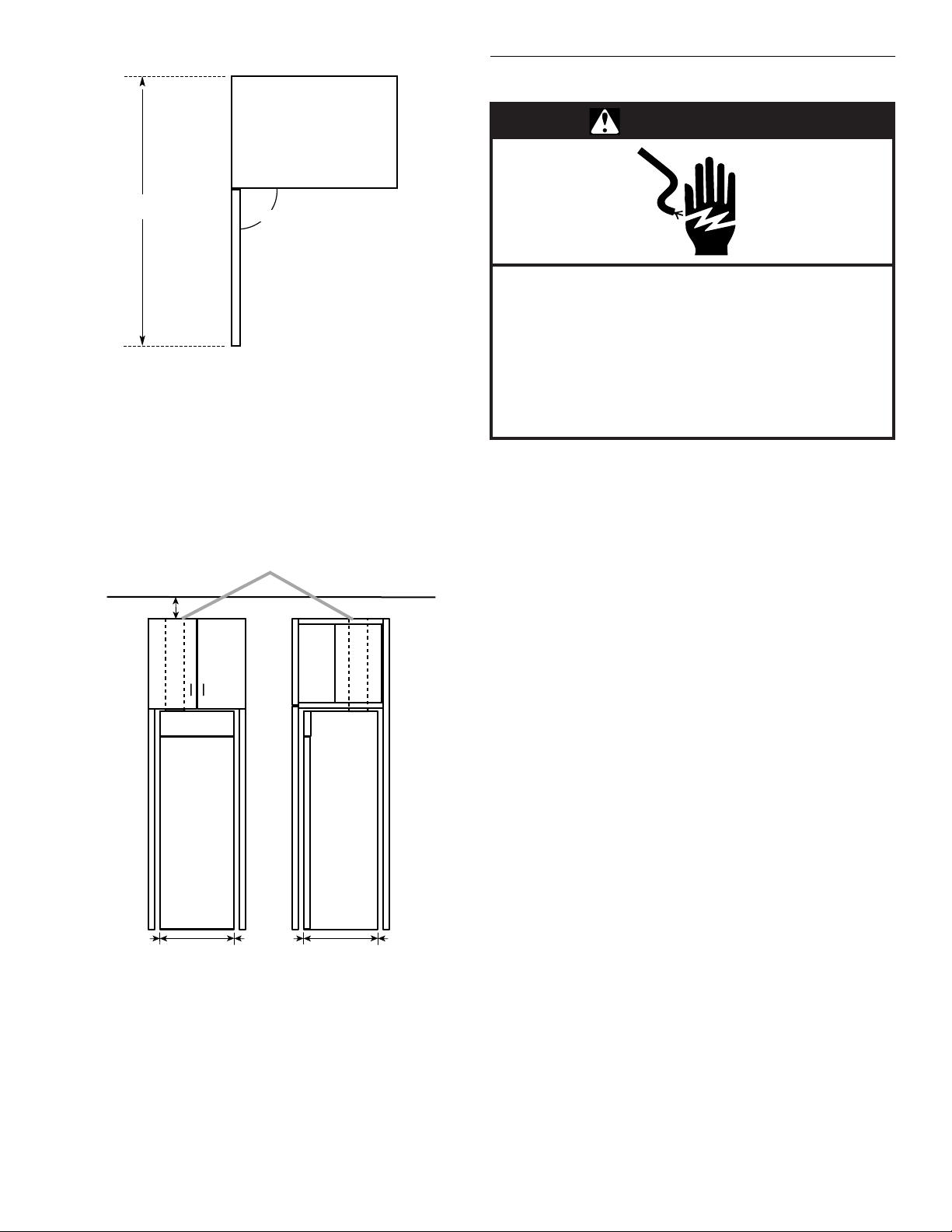
Drying Cabinet Door Swing Dimensions
46.5"
(118.1 cm)
90˚
Minimum installation spacing for custom cabinetry or trim
kit installation
The dimensions shown following are for the minimum spacing
allowed.
■ Additional spacing should be considered for ease of
installation and servicing.
■ Additional clearances might be required for wall, door and
floor moldings.
■ For built-in installation, minimum ventilation openings in the
top are required.
3
12" (30.5 cm) min.
Electrical Requirements
WARNING
Electrical Shock Hazard
Plug into a grounded 3 prong outlet.
Do not remove ground prong.
Do not use an adapter.
Do not use an extension cord.
Failure to follow these instructions can result in
death, fire, or electrical shock.
It is your responsibility
■ To contact a qualified electrical installer if an electrical outlet
is not currently available.
■ To be sure that the electrical connection is adequate and in
conformance with the National Electrical Code, ANSI/NFPA
70-latest edition and all local codes and ordinances.
A copy of the above code standards can be obtained from:
National Fire Protection Association, Batterymarch Park,
Quincy, MA 02269.
(59.4 cm)
0"
0" 24"
(61 cm)
0"0" 23.4"
12
1. Front view
2. Side view
3. Open to the outside of the enclosure for
airflow (see “Venting Requirements”)
Electrical Connection
To properly install your drying cabinet, you must determine the
type of electrical connection you will be using and follow the
instructions provided for it here.
■ The drying cabinet should be connected to a 120 V 60 Hz
3 prong grounded outlet.
■ The drying cabinet is ready for connection with a 5 ft.
(152.4 cm) long cable with a grounded plug. Use only the
supplied cable and plug.
■ The outlet should be located for easy plug removal.
If using a replacement power supply cord, it is recommended
that you use Power Supply Cord Replacement Part Number
8181928. For further information, please call the Customer
Interaction Center at 1-800-253-1301. In Canada, call
1-800-461-5681.
3
For a grounded, cord-connected drying cabinet:
This drying cabinet must be grounded. In the event of
malfunction or breakdown, grounding will reduce the risk of
electric shock by providing a path of least resistance for
electric current. This drying cabinet is equipped with a cord
having an equipment-grounding conductor and a grounding
plug. The plug must be plugged into an appropriate outlet that
is properly installed and grounded in accordance with all
local codes and ordinances.
1
2
WARNING:
Improper connection of the equipmentgrounding conductor can result in a risk of electric shock.
Check with a qualified electrician or service representative or
personnel if you are in doubt as to whether the drying cabinet
is properly grounded. Do not modify the plug provided with
the drying cabinet: if it will not fit the outlet, have a proper
outlet installed by a qualified electrician.
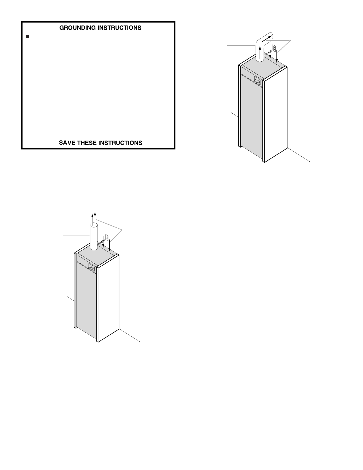
Venting Requirements
■ The drying cabinet should not be vented into a chimney, wall,
attic, ceiling or concealed space of a building.
■ The drying cabinet should vent into the room where the
drying cabinet is installed or into an adjacent room.
1
2
1. Venting into an adjacent room
2. Airflow in and out of the drying cabinet
■ Opening a door or window in the room where the drying
cabinet is installed is suggested for ventilation.
■ 4 in. (10.2 cm) heavy metal vent and clamps must be used.
Metal vent should not exceed 3 ft. (91.4 cm) in length.
■ If vented into the room where the drying cabinet is installed, a
minimum spacing of 12 in. (30.5 cm) from the metal vent to
the ceiling is suggested.
■ The drying cabinet must vent outside of the enclosure in
which it is installed.
■ Do not use an exhaust vent hood on the drying cabinet vent.
■ If custom cabinetry is built to enclose the top of the drying
cabinet, leave the venting area open to allow for airflow.
1. Venting into the same room
2. Airflow in and out of the drying cabinet
4
Unpack Drying Cabinet
2
3
Tip Over Hazard
Drying cabinet is top heavy and tips easily when
not completely installed.
Use two or more people to move and install
drying cabinet.
Failure to do so can result in serious injury
or cuts.
■ To prevent floor damage, set the drying cabinet onto the
cardboard prior to installation.
Install and Level Drying Cabinet
The drying cabinet may be installed with a panel trim kit or inside
custom cabinetry.
Move drying cabinet into position
1. Decide on the final location for the drying cabinet. Locate
existing wiring and plumbing to prevent drilling into or
severing wiring or plumbing during installation.
2. Keep the door taped closed until the drying cabinet is in its
final location.
3. As you slide the drying cabinet in so that it is flush and
centered with the cabinetry facing, route the power cord to
the 3 prong grounded outlet to avoid pinching the power
cord.
4. Remove tape and open the drying cabinet door. Slide out the
upper rack. Measure and note the distance from the drying
cabinet to the back panel or wall as shown.
1
2
3
4
1. Wall or panel behind drying cabinet
2. Wall stud
3. Back of drying cabinet
4. Mounting hole
5. Using a pencil, mark the location of the mounting holes on
the wall or back panel of the custom cabinetry. This will show
you the placement of the wood shim.
6. Slide the upper rack back and close the door. Keep the door
taped closed while it is being moved. Slide the drying cabinet
out.
7. Use a wood shim the thickness of the distance measured in
Step 4. The width of the shim cannot exceed 22 in. (55.9 cm)
or be less than 18 in. (45.7 cm). Attach the shim with the
appropriate length screws as shown.
NOTE: When attaching the shim, check to be sure that the
shim is attached solidly to the wall or custom cabinetry and
that the screws do not obstruct the drying cabinet mounting
holes.
1 2
3
1. Drying cabinet centered
2. Cabinetry door
3. Drying cabinet flush with cabinetry facing
1
1. Mounting hole markings
2. Wood shim
3. 18 in. (45.7 cm) Minimum/
22 in. (55.9 cm) Maximum width of shim
8. Slide the drying cabinet back into its final location. Remove
the door tape. Check to be sure that the shim is against the
back of the drying cabinet. If it is installed inside the custom
cabinetry, check that the front edge of the drying cabinet is
flush with the front of the custom cabinetry.
5
 Loading...