

Whirlpool LI31HC, W10526058F User Manual
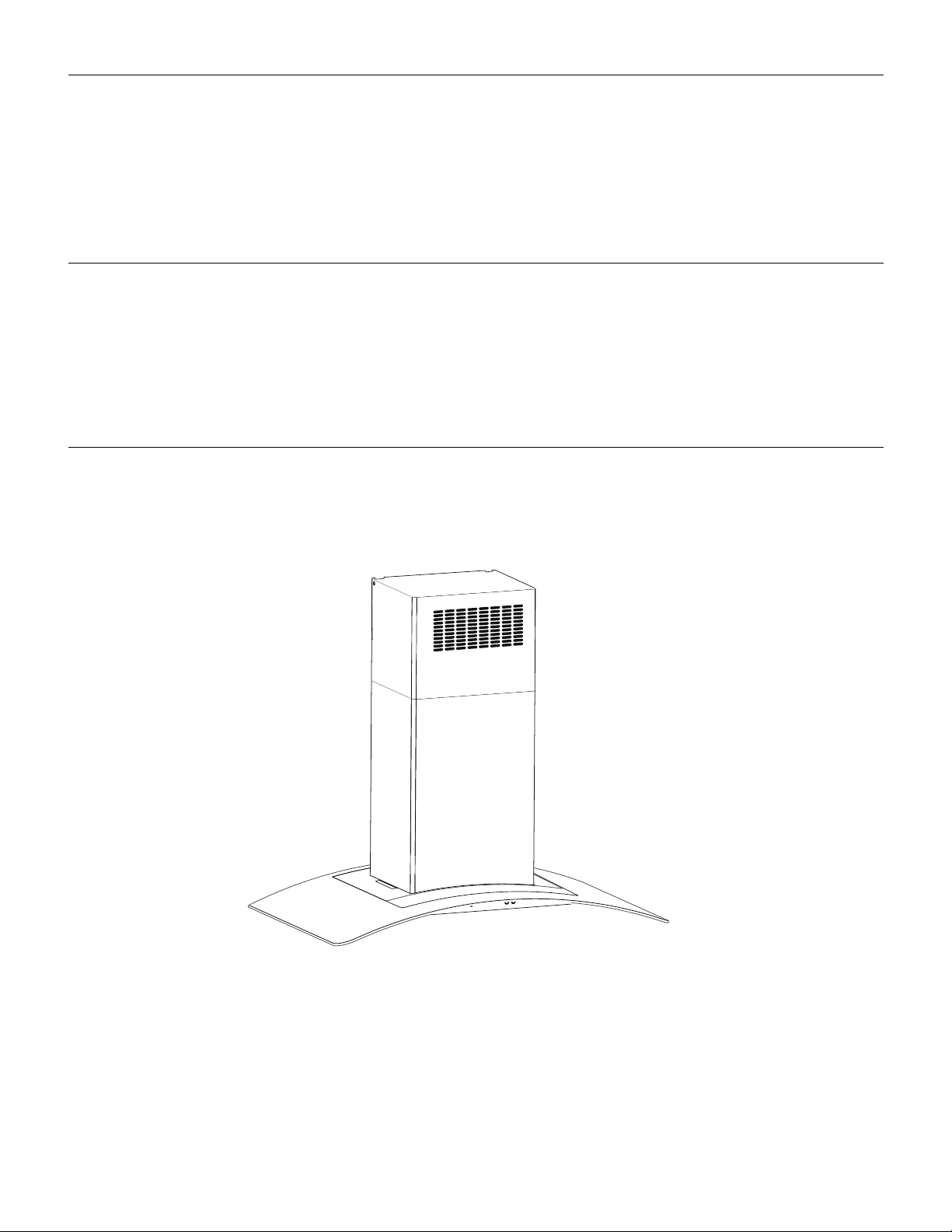
36" (91.4 CM) ISLAND-MOUNT CANOPY
IMPORTANT: READ AND SAVE THESE INSTRUCTIONS.
FOR RESIDENTIAL USE ONLY.
IMPORTANT : LIRE ET CONSERVER CES INSTRUCTIONS.
POUR UTILISATION RÉSIDENTIELLE UNIQUEMENT.
LI31HC/W10526058F
RANGE HOOD
Installation Instructions and Use & Care Guide
For questions about features, operation/performance, parts, accessories or service, call: 1-800-253-1301
or visit our website at www.whirlpool.com
In Canada, call 1-800-807-6777 or visit our website at www.whirlpool.ca
HOTTE DE CUISINIÈRE CONFIGURÉE EN ÎLOT
36" (91,4 CM)
Instructions d’installation et Guide d’utilisation et d’entretien
Au Canada, pour assistance, installation ou service, composer
le 1-800-807-6777 ou visiter notre site Web à
www.whirlpool.ca
Table of Contents/Table des matières.............................................................................2
TABLE OF CONTENTS
You can be killed or seriously injured if you don't immediately
You
can be killed or seriously injured if you don't
follow
All safety messages will tell you what the potential hazard is, tell you how to reduce the chance of injury, and tell you what can
happen if the instructions are not followed.
Your safety and the safety of others are very important.
We have provided many important safety messages in this manual and on your appliance. Always read and obey all safety
messages.
This is the safety alert symbol.
This symbol alerts you to potential hazards that can kill or hurt you and others.
All safety messages will follow the safety alert symbol and either the word “DANGER” or “WARNING.”
These words mean:
follow instructions.
instructions.
DANGER
WARNING
State of California Proposition 65 Warnings:
WARNING: This product contains one or more chemicals known to the State of California to cause cancer.
WARNING: This product contains one or more chemicals known to the State of California to cause birth defects or other
reproductive harm.
TABLE DES MATIÈRES
RANGE HOOD SAFETY .................................................................2
INSTALLATION REQUIREMENTS................................................4
Tools and Parts ............................................................................4
Location Requirements................................................................4
Venting Requirements..................................................................5
Electrical Requirements ...............................................................6
INSTALLATION INSTRUCTIONS..................................................7
Prepare Location..........................................................................7
Assemble Range Hood ................................................................8
Install Range Hood.......................................................................8
Make Electrical Connection .........................................................9
Install Duct Covers.....................................................................10
Complete Installation .................................................................11
RANGE HOOD USE......................................................................12
Range Hood Controls ................................................................12
RANGE HOOD CARE...................................................................13
Cleaning......................................................................................13
WIRING DIAGRAM ......................................................................14
ASSISTANCE OR SERVICE.........................................................15
In the U.S.A. ...............................................................................15
In Canada ...................................................................................15
Accessories................................................................................15
WARRANTY ..................................................................................16
SÉCURITÉ DE LA HOTTE DE CUISINIÈRE................................17
EXIGENCES D'INSTALLATION...................................................19
Outils et pièces...........................................................................19
Exigences d’emplacement.........................................................19
Exigences concernant l'évacuation ...........................................20
Spécifications électriques ..........................................................21
INSTRUCTIONS D’INSTALLATION.............................................22
Préparation de l'emplacement...................................................22
Assemblage de la hotte..............................................................23
Installation de la hotte ................................................................23
Raccordement électrique...........................................................24
Installation des cache-conduits .................................................25
Achever l'installation ..................................................................26
UTILISATION DE LA HOTTE .......................................................27
Commandes de la hotte de cuisinière .......................................27
ENTRETIEN DE LA HOTTE..........................................................28
Nettoyage ...................................................................................28
SCHÉMA DE CÂBLAGE...............................................................29
ASSISTANCE OU SERVICE.........................................................30
Au Canada..................................................................................30
Accessoires ................................................................................30
GARANTIE.....................................................................................31
RANGE HOOD SAFETY
2

IMPORTANT SAFETY INSTRUCTIONS
READ AND SAVE THESE INSTRUCTIONS
WARNING: TO REDUCE THE RISK OF FIRE, ELECTRIC
SHOCK, OR INJURY TO PERSONS, OBSERVE THE
FOLLOWING:
■ Use this unit only in the manner intended by the
manufacturer. If you have questions, contact the
manufacturer.
■ Before servicing or cleaning the unit, switch power off at
service panel and lock the service disconnecting means to
prevent power from being switched on accidentally. When
the service disconnecting means cannot be locked,
securely fasten a prominent warning device, such as a tag,
to the service panel.
■ Installation work and electrical wiring must be done by
qualified person(s) in accordance with all applicable codes
and standards, including fire-rated construction.
■ Do not operate any fan with a damaged cord or plug.
Discard fan or return to an authorized service facility for
examination and/or repair.
■ Sufficient air is needed for proper combustion and
exhausting of gases through the flue (chimney) of fuel
burning equipment to prevent backdrafting. Follow the
heating equipment manufacturer's guideline and safety
standards such as those published by the National Fire
Protection Association (NFPA), the American Society for
Heating, Refrigeration and Air Conditioning Engineers
(ASHRAE), and the local code authorities.
■ When cutting or drilling into wall or ceiling; do not damage
electrical wiring and other utilities.
■ Ducted fans must always be vented outdoors.
CAUTION: For general ventilating use only. Do not use
to exhaust hazardous or explosive materials and vapors.
CAUTION: To reduce risk of fire and to properly exhaust
air, be sure to duct air outside - do not vent exhaust air into
spaces within walls or ceilings, attics or into crawl spaces,
or garages.
WARNING: TO REDUCE THE RISK OF FIRE, USE ONLY
METAL DUCTWORK.
WARNING: TO REDUCE THE RISK OF A RANGE TOP
GREASE FIRE:
■ Never leave surface units unattended at high settings.
Boilovers cause smoking and greasy spillovers that may
ignite. Heat oils slowly on low or medium settings.
■ Always turn hood ON when cooking at high heat or when
flambeing food (i.e. Crepes Suzette, Cherries Jubilee,
Peppercorn Beef Flambé).
■ Clean ventilating fans frequently. Grease should not be
allowed to accumulate on fan or filter.
■ Use proper pan size. Always use cookware appropriate for
the size of the surface element.
WARNING: TO REDUCE THE RISK OF INJURY TO
PERSONS IN THE EVENT OF A RANGE TOP GREASE
FIRE, OBSERVE THE FOLLOWING:
a
■ SMOTHER FLAMES with a close fitting lid, cookie sheet, or
metal tray, then turn off the burner. BE CAREFUL TO
PREVENT BURNS. If the flames do not go out
immediately, EVACUATE AND CALL THE FIRE
DEPARTMENT.
■ NEVER PICK UP A FLAMING PAN - you may be burned.
■ DO NOT USE WATER, including wet dishcloths or towels -
a violent steam explosion will result.
■ Use an extinguisher ONLY if:
– You know you have a class ABC extinguisher, and you
already know how to operate it.
– The fire is small and contained in the area where it
started.
– The fire department is being called.
– You can fight the fire with your back to an exit.
a
Based on "Kitchen Fire Safety Tips" published by NFPA.
■ WARNING: To reduce the risk of fire or electrical shock,
do not use this fan with any solid-state speed control
device.
3

INSTALLATION REQUIREMENTS
†®TORX and T20 are registered trademarks of
Acument Intellectual Properties
, Inc.
Tools and Parts
Gather the required tools and parts before starting installation.
Read and follow the instructions provided with any tools listed here.
Tools needed
■ Level
■ Drill with 1¼" (3.0 cm), ³⁄₈" (9.5 mm), ⁷⁄₆₄" (2.75 mm) and ¹⁄₈"
(3.0 mm) drill bits
■ Pilot hole drill bits (determined by chimney support
attachment method)
■ Pencil
■ Wire stripper or utility knife
■ Tape measure or ruler
■ Pliers
■ Caulking gun and weatherproof caulking compound
■ Vent clamps
■ Jigsaw or keyhole saw
■ Flat-blade screwdriver
■ Metal snips
■ Phillips screwdriver
Parts needed
■ Home power supply cable
■ ½" (12.7 mm) UL listed or CSA approved strain relief
■ 3 UL listed wire connectors
For vented installations, you will also need:
■ 1 wall or roof cap
■ Metal vent system
For non-vented (recirculating) installations, you will also need:
■ Recirculating Kit Part Number W10294734 for non-vented
(recirculating) installations only. See “Assistance or Service”
section to order.
■ 6" (15.2 cm) round metal vent duct. Length required is
determined by ceiling height.
Parts supplied
Remove parts from packages. Check that all parts are included.
■ Hood ventilator assembly with canopy glass, retainer
brackets, rubber seals, and light bulb installed.
■ Metal grease filter
■ 60 - 4.2 x 8 mm screws
■ 4 - 3.5 x 6.5 mm screws
■ 4 - 5 x 45 mm screws
■ 2 - 2.9 x 3 mm screws
■ T10 Torx
■ T20
■ 2 - Upper vent covers
■ 2 - Lower vent covers
■ 4 - Plastic vent clips
■ Mounting template
■ Upper horizontal support bracket
■ Horizontal support
■ 8 - Vertical supports
■ Vent transition with back draft damper installed.
■ 2 - 3.5 x 9.5 mm mounting screws
®†
adapter
®†
Tor x® adapter
Location Requirements
IMPORTANT: Observe all governing codes and ordinances.
Have a qualified technician install the range hood. It is the installer's
responsibility to comply with installation clearances specified on the
model/serial rating plate. The model/serial rating plate is located
behind the left filter on the rear wall of the vent hood.
Canopy hood location should be away from strong draft areas,
such as windows, doors and strong heating vents.
Cabinet opening dimensions that are shown must be used. Given
dimensions provide minimum clearance.
Grounded electrical outlet is required. See “Electrical
Requirements” section.
Because of the size and weight of this island hood, the chimney
support must be securely attached to the ceiling.
■ For plaster or drywall ceilings, the chimney support must be
attached to joists. If this is not possible, you must build a
support structure behind the plaster or drywall. The support
structure must be able to support 80 lbs (36.6 kg).
This range hood is recommended for use with cooktops with a
maximum total rating of 60,000 BTUs or less.
The range hood is factory set for venting through the roof or wall.
For non-vented (recirculating) Installation see “Non-vented
(recirculating) Installation” in “Install Range Hood” section.
Recirculating Kit Part Number W10294734 is available from your
dealer or an authorized parts distributor.
All openings in ceiling and wall where range hood will be installed
must be sealed.
For Mobile Home Installations
The installation of this range hood must conform to the
Manufactured Home Construction Safety Standards, Title 24
CFR, Part 328 (formerly the Federal Standard for Mobile Home
Construction and Safety, Title 24, HUD, Part 280) or when such
standard is not applicable, the standard for Manufactured Home
Installation 1982 (Manufactured Home Sites, Communities and
Setups) ANSI A225.1/NFPA 501A, or latest edition, or with local
codes.
4
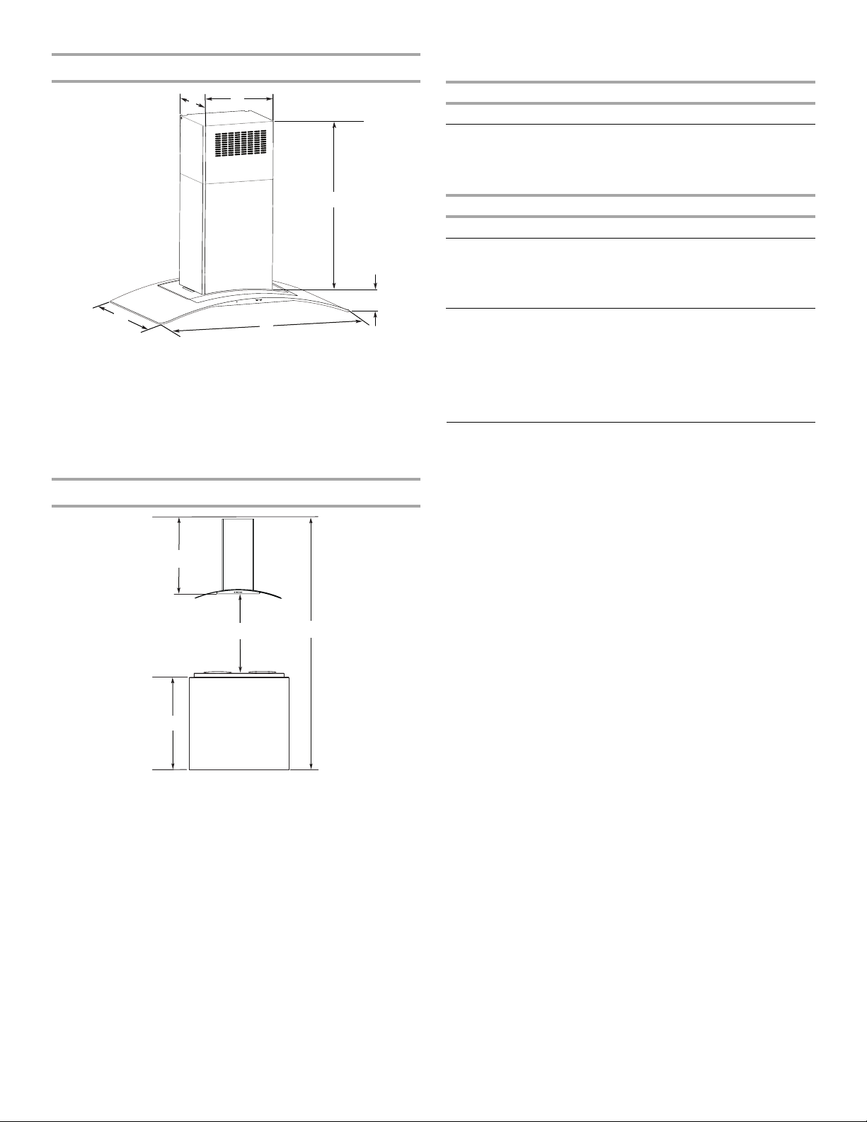
Product Dimensions
A
B
C
D
E
F
A
B
D
C
A. 12¼" (31.1 cm)
B. 13
³⁄₁₆
" (33.5 cm)
C. *29
³⁄₄
" (75.6 cm) min. 44
**29
³⁄₄
" (75.6 cm) min. 49
D. 3
¹⁄₂
" (8.9 cm)
E. 36" (91.4 cm)
F. 2 5
³⁄₁₆
" (64.0 cm)
*Vented installations only
**Non-vented (recirculating) installations only
Installation Dimensions
A. Countertop height
B. Hood height from ceiling to bottom of the range
hood filter surface: D-A-C=B
C. Hood height: 24" (61.0 cm) min. from electric
cooking surface, 27" (68.6 cm) min. from gas
cooking surface, suggested 36" (91.4 cm) max.
D. Ceiling height
IMPORTANT:
Minimum distance “C”: 24" (61.0 cm) from electric cooking
surface, 27" (68.6 cm) from gas cooking surface
Suggested maximum distance “C”: 36" (91.4 cm)
¹³⁄₁₆
" (113.8 cm) max.
¹³⁄₁₆
" (126.5 cm) max.
The chimneys can be adjusted for different ceiling heights. See
the following chart.
Vented Installations
Min. ceiling height Max. ceiling height
Electric cooking
7' 8" (2.34 m) 9' 10" (3.0 m)
surface
Gas cooking
7'11" (2.41 m) 9' 10" (3.0 m)
surface
Non-vented (recirculating) Installations
Min. ceiling height Max. ceiling height
Electric cooking
7' 8" (2.34 m) 10' 3" (3.12 m)
surface
Gas cooking
7'11" (2.41 m) 10' 3" (3.12 m)
surface
*NOTE: The range hood chimneys are adjustable and designed
to meet varying ceiling or soffit heights depending on the
distance “C” between the bottom of the range hood and the
cooking surface. For higher ceilings, a Stainless Steel Chimney
Extension Kit Part Number W10688278 is available from your
dealer or an authorized parts distributor. The chimney extension
replaces the chimney shipped with the range hood.
Venting Requirements
■ Vent system must terminate to the outside, except for non-
vented (recirculating) installations.
■ Do not terminate the vent system in an attic or other enclosed
area.
■ Do not use 4" (10.2 cm) laundry-type wall caps.
■ Use metal vent only. Rigid metal vent is recommended. Do
not use plastic or metal foil vent.
■ The vent system must have a damper. If the roof or wall cap
has a damper, do not use the damper supplied with the range
hood.
For the most efficient and quiet operation:
■ Use a straight run or as few elbows as possible.
■ Use no more than three 90° elbows.
■ Make sure there is a minimum of 24" (61.0 cm) of straight
vent between the elbows if more than 1 elbow is used.
■ Do not install 2 elbows together.
■ Use vent clamps to seal all joints in the vent system.
■ Use caulking to seal exterior wall or roof opening around the
cap.
■ The size of the vent should be uniform.
Cold Weather Installations
An additional back draft damper should be installed to minimize
backward cold air flow and a thermal break should be installed to
minimize conduction of outside temperatures as part of the vent
system. The damper should be on the cold air side of the thermal
break.
The break should be as close as possible to where the vent
system enters the heated portion of the house.
Makeup Air
Local building codes may require the use of makeup air systems
when using ventilation systems greater than specified CFM of air
movement. The specified CFM varies from locale to locale.
Consult your HVAC professional for specific requirements in your
area.
5
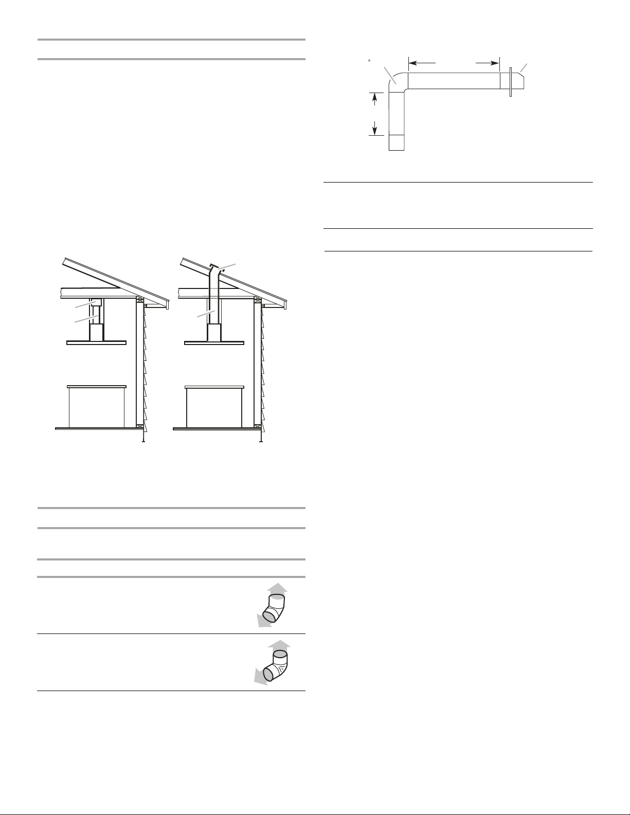
Venting Methods
B
A
B
A
90 elbow
6 ft (1.8 m)
2 ft
(0.6 m)
Wall cap
This island hood is factory set for venting through the roof.
A 6" (15.2 cm) round vent system is needed for installation (not
included). The hood exhaust opening is 6" (15.2 cm) round.
NOTE: Flexible vent is not recommended. Flexible vent creates
back pressure and air turbulence that greatly reduce
performance.
Vent system can terminate either through the roof or wall. To vent
through a wall, a 90° elbow is needed.
For Non-Vented (recirculating) Installations
If it is not possible to vent cooking fumes and vapors to the
outside, the hood can be used in the non-vented (recirculating)
version, fitting a charcoal filter and the deflector. Fumes and
vapors are recycled through the top of the grille. To order, see the
“Assistance or Service” section.
Non-vented (recirculating) Roof Venting
A. Deflector
B. 6" (15.2 cm) round vent
A. Roof cap
B. 6" (15.2 cm) round vent
NOTE: If codes permits, wall venting can be an option for 2-story
homes.
Calculating Vent System Length
To calculate the length of the system you need, add the
equivalent feet (meters) for each vent piece used in the system.
Vent piece 6" (15.2 cm) round
45° elbow 2.5 ft
(0.8 m)
90° elbow 5.0 ft
Maximum equivalent vent length is 35 ft (10.7 m).
(1.5 m)
Example Vent System
The following example falls within the maximum vent length of
35 ft (10.7 m).
1 - 90° elbow = 5.0 ft (1.5 m)
1 - wall cap = 0.0 ft (0.0 m)
8 ft (2.4 m) straight = 8.0 ft (2.4 m)
System length = 13 ft (3.9 m)
Electrical Requirements
Observe all governing codes and ordinances.
Ensure that the electrical installation is adequate and in
conformance with National Electrical Code, ANSI/NFPA 70 (latest
edition), or CSA Standards C22.1-94, Canadian Electrical Code,
Part 1 and C22.2 No. 0-M91 (latest edition) and all local codes
and ordinances.
If codes permit and a separate ground wire is used, it is
recommended that a qualified electrician determine that the
ground path is adequate.
A copy of the above code standards can be obtained from:
National Fire Protection Association
1 Batterymarch Park
Quincy, MA 02169-7471
CSA International
8501 East Pleasant Valley Road
Cleveland, OH 44131-5575
■ A 120 volt, 60 Hz., AC only, 15-amp, fused electrical circuit is
required.
■ If the house has aluminum wiring, follow the procedure
below:
1. Connect a section of solid copper wire to the pigtail
leads.
2. Connect the aluminum wiring to the added section of
copper wire using special connectors and/or tools
designed and UL listed for joining copper to aluminum.
Follow the electrical connector manufacturer's recommended
procedure. Aluminum/copper connection must conform with
local codes and industry accepted wiring practices.
■ Wire sizes and connections must conform with the rating of
the appliance as specified on the model/serial rating plate.
The model/serial plate is located behind the filter on the rear
wall of the range hood.
■ Wire sizes must conform to the requirements of the National
Electrical Code, ANSI/NFPA 70 (latest edition), or CSA
Standards C22. 1-94, Canadian Electrical Code, Part 1 and
C22.2 No. 0-M91 (latest edition) and all local codes and
ordinances.
6
INSTALLATION INSTRUCTIONS
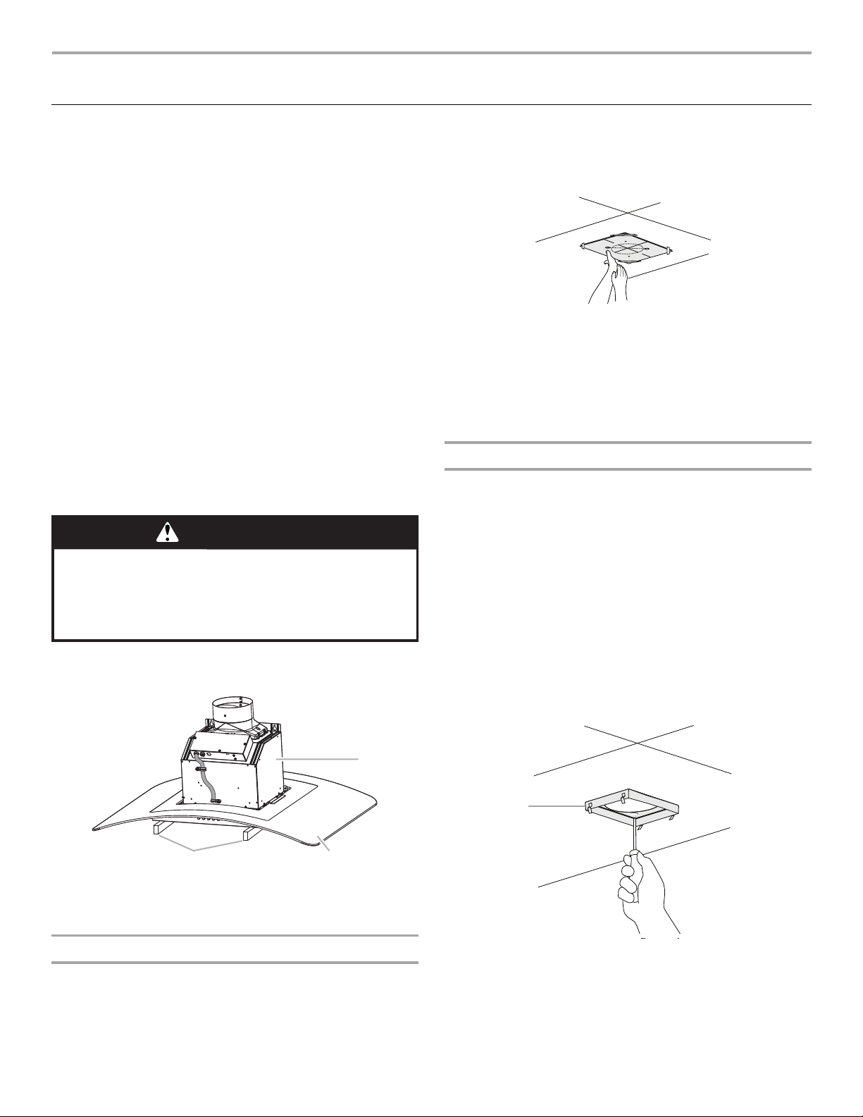
WARNING
Excessive Weight Hazard
Use two or more people to move and install
range hood.
Failure to do so can result in back or other injury.
A
B
C
A
Prepare Location
■ Lay out the vent duct system before installing the range hood
to determine the best routing for the vent duct.
■ It is recommended that the vent system be installed before
the range hood is installed.
■ Before making cutouts, make sure there is proper clearance
within the ceiling for exhaust vent.
■ Range hood is to be installed 24" (61.0 cm) min. for electric
cooking surfaces, 27" (68.6 cm) min. for gas cooking
surfaces, to a suggested maximum of 36" (91.4 cm) above
the cooking surface.
■ Remove film from metal surfaces as needed prior to
assembly.
■ Check your ceiling height and the range hood height
maximum before you install your hood.
1. Disconnect power.
2. Determine which venting method to use: roof, wall or non-
vented.
3. Select a flat surface for assembling the range hood. Place
covering over that surface. Place two 3" (7.6 cm) high
spacers (not included) onto the covered surface.
NOTE: Cover the spacers to avoid damage to the range hood
surface.
4. Using 2 or more people, lift range hood onto covered
spacers.
2. Tape template in place on the ceiling at the marked
centerline. The line for the front of the range hood should be
parallel to the front of the cooktop.
3. Use a pencil to mark the mounting screws, wire access and
duct hole locations on the ceiling.
NOTE: Mounting hole locations should be into a ceiling
support structure capable of holding 80 lbs (36.6 kg).
Remove the template.
4. Drill 4 - ³⁄₁₆" (4.8 mm) pilot holes for mounting the upper
horizontal support.
Complete Preparation
1. Determine the required location for the home power supply
cable and drill a ½" (1.3 cm) diameter hole for wire access.
2. Run ½" (1.3 cm) conduit and wires or home power supply
cable according to the National Electrical Code or CSA
Standards and local codes and ordinances. There must be
enough ½" conduit and wires or home power supply cable
from the fused disconnect (or circuit breaker) box to make the
connection in the hood’s electrical terminal box.
NOTE: Do not reconnect power until installation is complete.
3. For vented installations only: Using a jigsaw or keyhole
saw, cut a 6½" (16.5 cm) diameter hole for the vent duct.
4. Attach the upper horizontal support bracket with 4 - 5 x
45 mm wood screws.
NOTE: Upper horizontal support screws must be into a
ceiling support structure capable of holding 80 lbs (36.6 kg).
A. Covered spacers
B. Glass canopy
C. Ventilator assembly
Range Hood Mounting Screws Installation
1. Determine and mark the centerline on the ceiling where the
range hood will be installed, considering the requirements for
ceiling support structures. See the “Location Requirements”
section. Make sure the range hood is centered over the
cooking surface.
A. Upper horizontal support
7
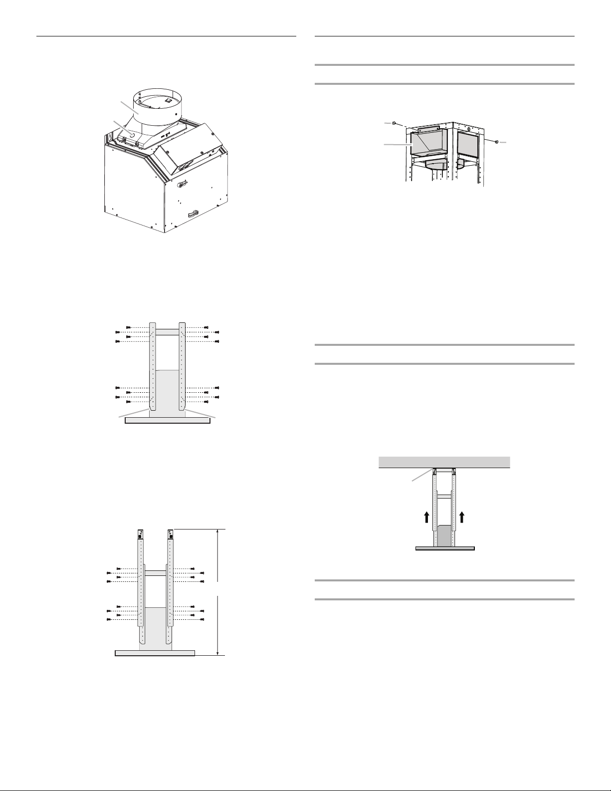
Assemble Range Hood
B
A
B
A
A
C
C
B
A
A
B
A
1. Install transition on top of hood (if removed for shipping) with
2 - 3.5 x 9.5 mm sheet metal screws.
A. Vent transition
B. 3.5 x 9.5 mm screw (2)
2. Position the 4 vertical supports (A) with the notches at the
bottom and attach to the range hood using 16 - 4.2 x 8 mm
screws.
3. Attach the horizontal support (B) using 8 - 4.2 x 8 mm screws.
Install Range Hood
Non-Vented (recirculating) Installation
1. Attach the air deflector to the upper horizontal support using
2 mounting screws.
B
A
A. Deflector
B. Mounting screws
2. Measure the length of 6" (15.2 cm) duct needed to connect
the transition to the deflector.
NOTE: Vent should fit up inside the deflector 1" (2.5 cm)
minimum.
3. Install vent between the transition and the deflector.
NOTE: To make vent installation easier, temporarily remove
the deflector from the chimney support bracket and replace
after vent section is in place.
4. Seal all connections with vent clamps. Continue with “Range
Hood Installation” in this section.
Range Hood Installation
1. Using 2 or more people, lift the range hood assembly and
attach it by snapping the vertical supports to the spring clips
in the upper horizontal support bracket that is mounted to the
ceiling.
NOTE: The range hood assembly must be held in place while
A. Vertical supports
B. Horizontal support
C. Notched end
4. Attach a second set of vertical supports (A) and set the
vertical height (B). See “Installation Dimensions” in the
“Location Requirements” section to help determine the
desired dimension for vertical height “B.”
Secure with 16 - 4.2 x 8 mm T20
®
screws.
you are installing the screws in the next step.
2. Install 16 - 4.2 x 8 mm screws and tighten to secure.
A. Mounting screws
Connect Vent System
1. Install vent system.
2. Push duct over the exhaust outlet. Seal all connections with
vent clamps.
A. Vertical supports
B. Vertical height
3. Use caulk to seal all openings.
8
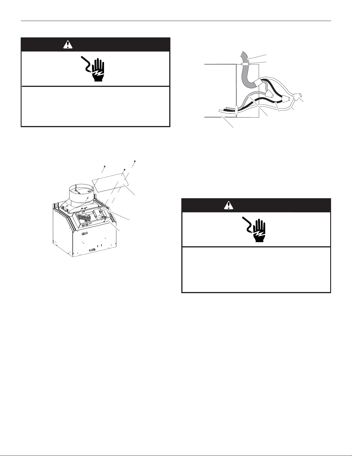
Make Electrical Connection
WARNING
Electrical Shock Hazard
Disconnect power before servicing.
Replace all parts and panels before operating.
Failure to do so can result in death or electrical shock.
C
B
A
A
B
C
D
E
F
G
WARNING
Electrical Shock Hazard
Electrically ground blower.
Connect ground wire to green and yellow ground wire
in terminal box.
Failure to do so can result in death or electrical shock.
1. Disconnect power.
2. Remove terminal box cover.
3. Remove the knockout in the terminal box and install a UL
listed or CSA approved ¹⁄₂" strain relief.
4. Run home power supply cable through strain relief, into
terminal box.
A. Home power supply cable
B. UL listed or CSA approved
strain relief
C. UL listed wire connectors
D. White wires
5. Use UL listed wire connectors and connect black wires (E)
together.
6. Use UL listed wire connectors and connect white wires (D)
together.
E. Black wires
F. Green (or bare) and yellow-
green ground wires
G. Terminal box
A. Terminal box
B. Knockout
C. Terminal box cover
7. Connect green (or bare) ground wire from home power supply
to yellow-green ground wire (F) in terminal box using UL listed
wire connectors.
8. Tighten strain relief screw.
9. Install terminal box cover.
10. Check that all light bulbs are secure in their sockets.
11. Reconnect power.
9
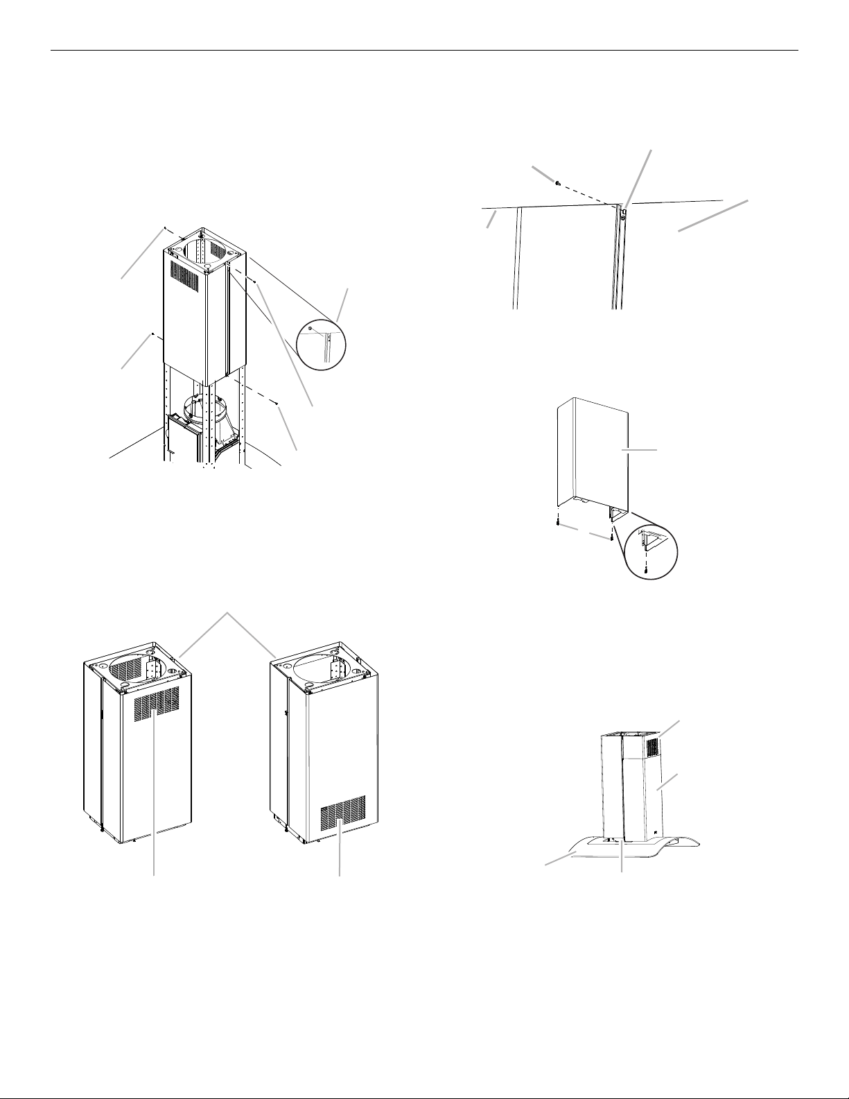
Install Duct Covers
A
A
B
C
C
A
B
C
B
C
A
D
B
A
A
B
D
C
NOTE: Remove the film from the duct covers.
1. Assemble the upper duct covers together and install the duct
covers around the support frame. The larger hole in the
flanges of the upper duct cover must be outside the smaller
hole in the mating flange of the other upper duct cover.
2. Secure the upper duct covers together with two 3.5 x 6.5 mm
screws at the top and two 2.9 x 3 mm screws at the bottom.
Install 1 screw on each side at the top and bottom of the
assembled duct covers.
3. Slide the upper duct covers up the frame to the ceiling and
secure to the upper horizontal support with 2 - 3.5 x 6.5 mm
screws.
A. 3.5 x 6.5 mm Screws (2)
B. Assembly holes (larger hole outside of
smaller hole on both sides)
C. 2.9 x 3 mm screws (2)
NOTE: For non-vented (recirculating) installation, the slotted
holes in the upper duct covers will be visible when assembled.
For vented installations, the slotted holes will be hidden down
inside the lower duct covers.
A. 3.5 x 6.5 mm screw
B. Slotted holes (2)
C. Upper duct covers
D. Ceiling
4. Place the long end of the plastic clips (2) into the bottom of
the front lower duct cover.
A. Lower duct cover - (front)
B. Plastic clips (2) (long end for front placement)
5. Install the lower duct cover (front) to the range hood canopy.
Spread the lower duct cover opening slightly and position it
over the upper duct cover. Set the lower duct cover in place.
Position so the flanges of the lower duct cover set into the
flanges of the upper duct covers.
A. Top toward ceiling
B. Slots installed up for non-vented installations
C. Slots installed down for vented installations
A. Range hood canopy
B. Plastic clips
C. Lower duct covers
D. Upper duct covers
10
 Loading...