

Whirlpool WGD5590VQ1, WGD5590VQ0, LGV4634PQ1 Installation Guide
29IN.(73.7CM)LONGVENTGASDRYER
INSTALLATIONINSTRUCTIONS
INSTRUCTIONSD'INSTALLATIONPOURSECHEUSEAGAZ
AEVENTDE29PO (73,7CM)DELONG
TableofContents/Table desmati_res
DRYER SAFETY ..................................................... 1
INSTALLA'nON INSTRUCTIONS .......................... 2
Tools and Parts ................................................... 2
Location Requirements ...................................... 3
Electrical Requirements ...................................... 4
Gas Supply Requirements .................................. 4
Venting Requirements ......................................... 5
PlanVent System ................................................ 6
Install Vent System .............................................. 8
Install leveling Legs ............................................ 8
Level Dryer........................................................... 8
Make Gas Connection ........................................ g
Connect Vent ....................................................... 9
Reverse Door Swing (Optional) ........................... g
Complete Installation......................................... 10
SECURITE DE LA SECHEUSE ............................ 11
INSTRUCTIONS D'INSTALLATION .................... 12
Outillage et pi_ces n_cessaires ........................ 12
Emplacement d'installation ............................... 12
Specifications _lectriques ................................. 13
Alimentation en gaz ........................................... 14
Exigences concernant I'_vacuation .................. 15
Planification du syst_me d'_vacuation ............. 16
Installation du conduit d'_vacuation ................. 18
Installation des pieds de nivellement ................ 18
Mise & niveau de la s_cheuse ........................... 18
Raccordement au gaz ....................................... 18
Conduit d'_vacuation ........................................ 19
Inversion de I'ouverture de la porte (facultatit).. 19
Achever I'installation ......................................... 20
DRYER8AR_TY
Your safety and the safety of others are very important.
We have provided many important sarety messages in this manual and on your appliance. Always read and obey all safety
messages.
This is the safety alert symbol.
This symbol alerts you to potential hazards that can kill or hurt you and others.
All safety messages will follow the safety alert symbol and either the word "DANGER" or "WARNING."
These words mean:
You can be killed or seriously Injured If you don't Immediately
follow Instructions.
You can be killed or seriously Injured If you don't follow
Instructions.
All safety messages will tell you what the potential hazard is, tell you how to reduce the chance of injury, and tell you what can
happen if the instructions are not followed.
IMPORTANT SAFETY INSTRUCTIONS
Whendiscardingor storingyouroldclothesdryer,removethe door.
I
SAVE THESE INSTRUCTIONS
8535900
WARNING: For your safety, the information in this manual must be followed to minimize
the risk of fire or explosion, or to prevent property damage, personal injury, or death.
- Do not store or use gasoline or other flammable vapors and liquids in the vicinity of this
or any other appliance.
-WHAT TO DO IFYOU SMELL GAS:
• Do not try to light any appliance.
• Do not touch any electrical switch; do not use any phone in your building.
• Clear the room, building, or area of all occupants.
• Immediately call your gas supplier from a neighbor's phone. Follow the gas supplier's
instructions.
• If you cannot reach your gas supplier, call the fire department.
- Installation and service must be performed by a qualified installer, service agency, or
the gas supplier,
In the State of Massachusetts, the following installation instructionsapply:
• Installations and repairs must be performed by a qualified or licensed contractor, plumber, or gasfitter qualified or
licensed by the State of Massachusetts.
• If using a ball valve, it shall be a T-handle type.
• A flexible gas connector, when used, must notexceed 3 feet.
INSTALLATIONINSTRUCTIONS
ToolsandParts
Check that you hove everything necessary for correct installation.
Proper installation isyour responsibility.
• 8 in. or 10 in. pipe wrench
• 8 in. or 10 in. adjustable
wrench (forgas
connections)
• Flat-blade screwdriver
• Adjustable wrench that
opens to 1 in. (2.5 cm) or
hex-hsad socket wrench
(for adjusting dryer feet)
• Level
• 1Ain. nut driver orsocket
wrench
• Knife
• Safety glasses
• Vent clamps
• Pipe-joint compound
resistant to L.P gas
• Caulking gun and
compound (for installing
new exhaust vent)
• Gloves
• Pliers
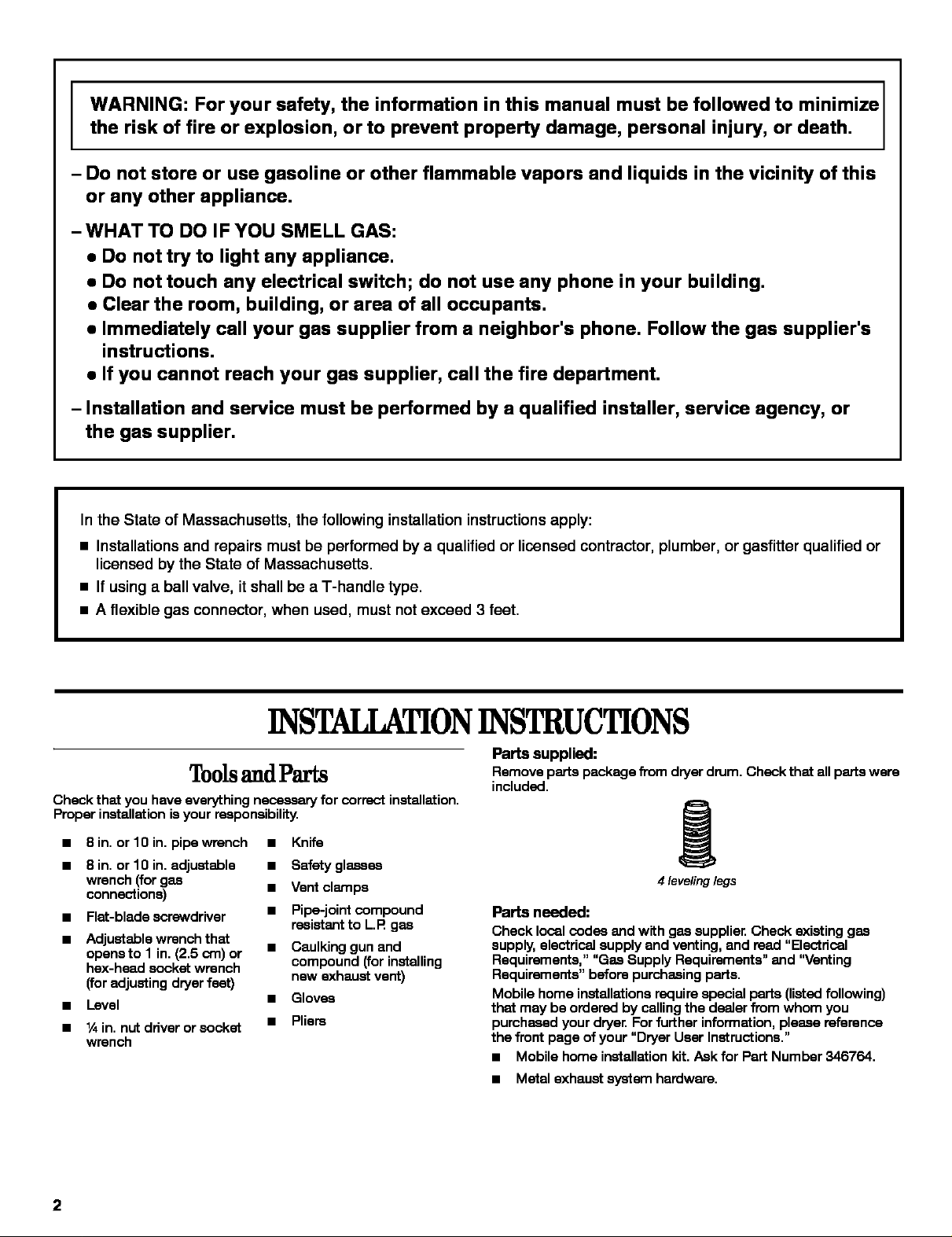
Parts supplied:
Remove parts package from dryer drum, Check that all parts were
included,
4 leveling legs
Parts needed:
Check local codas and with gas supplier. Check existing gas
supply, electrical supply and venting, and read "Electrical
Requirements," "Gas Supply Requirements" and "Venting
Requirements" before purchasing parts,
Mobile home installations require special parts (listedfollowing)
that may be ordered by calling the dealer from whom you
purchased your dryer, For further information, please reference
the front page of your "Dryer User Instructions,"
• Mobile home installation kit, Ask for Part Number 345764,
• Metal exhaust system hardware.
2
LocationRequirements
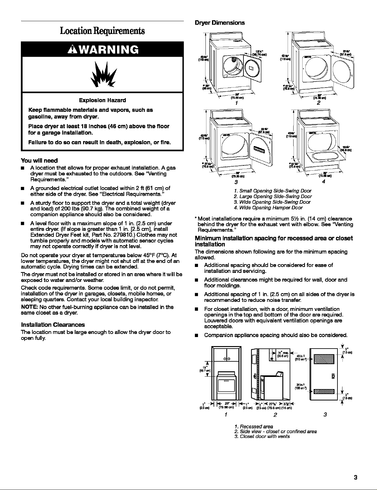
Dryer Dimensions
Explosion Hazard
Keep flammable materials and vapors, such as
geaollne, away from dryer,
Place dryer at least 18 Inches (46 cm) above the floor
for a garage Installation,
Fallura to do so can result In death, explosion, or flra,
You will need
a A location that allows for proper exhaust installation. A gee
dryer must be exhausted to the outdoors. See "Venting
Requirements."
a A grounded eleotdcal outlet located within 2 ft (61 cm) of
either side of the dryer. See "Electrical Requirements."
a A sturdy floor to support the dryer and a total weight (dryer
and load) of 200 Ibs (90.7 kg). The combined weight of a
companion appliance should also be considered.
= A level floor with a maximum slope of 1 in. (2.5 ore) under
entire dryer. (If slope is greater than 1 in. [2.5 cm], install
Extended Dryer Feet kit, Part No. 279810.) Clothes may not
tumble properly and models with automatic sensor cycles
may not operate correctly if dryer is not level.
Do not operate your dryer at temperatures below 45°F (7°(2)).At
lower temperatures, the dryer might not shut off at the end of an
automatic cycle. Drying times can be extended.
The dryer must not be installed orstored inan area where it will be
exposed to water and/or weather.
Check code requirements. Some codes limit, or do not permit,
installation of the dryer in garages, closets, mobile homes, or
sleeping quarters. Contact your local building inspector
NOTE: No other fuel-burning appliance can be installed inthe
same closet as a dryer.
Installation Clearances
The location must be large enough to allow the dryer door to
open fully.
(1
{_74 un)
1
3
1. Small Opening Side-Swing Door
2. Large Opening Side-Swing Door
3. Wide Opening Side-Swing Door
4. Wide Opening Hamper Door
2
4
* Meet installations require a minimum 5½ in. (14 cm) clearance
behind the dryer for the exhaust vent with elbow. See "Venting
Requirements."
Minimum installation spacing for recessed area or closet
installation
The dimensions shown following are forthe minimum spacing
allowed.
a Additional spacing should be considered for ease of
installation and servicing.
a
Additional clearances might be required for wall, door and
floor moldings.
a
Additional spacing of 1 in. (2.5 cm) on all sides of the dryer is
recommended to reduce noise transfer.
a
For closet installation,with a door, minimum ventilation
openings inthe top and bottom of the door are required.
Louvered doors with equivalent ventilation openings are
acceptable.
a Companion appliance spacing should also be considered.
i
m
olo
IY
v
24inA
i
_6_ (2Scm)_5cm 14cm
m
1 2
D
_3"
_sm)
3
1. Recessed area
2. Side view - closet or confined area
3. Closet door with vents
Mobile Home-Additional Installation Requirements
This dryer is suitable for mobile home installations.
The installation must conform to the Manufactured Home
Construction and Safety Standard, Title 24 CFR, Part 3280
(formerly the Federal Standard for Mobile Home Construction and
Safety, "ntle24, HUD Part 280) or the Canadian Manufactured
Home Standard, CAN/CSA-Z240 MH.
Mobile home installations require:
• Metal exhaust system hardware which is available for
purchase from your dealer.
• Mobile Home Installation Kit Part #346764, see "Tools and
Parts" section for ordering information.
Special provisions must be made in mobile homes to
introduce outside air into the dryeE The opening (such as a
nearby window) should be at least twice as large as the dryer
exhaust opening.
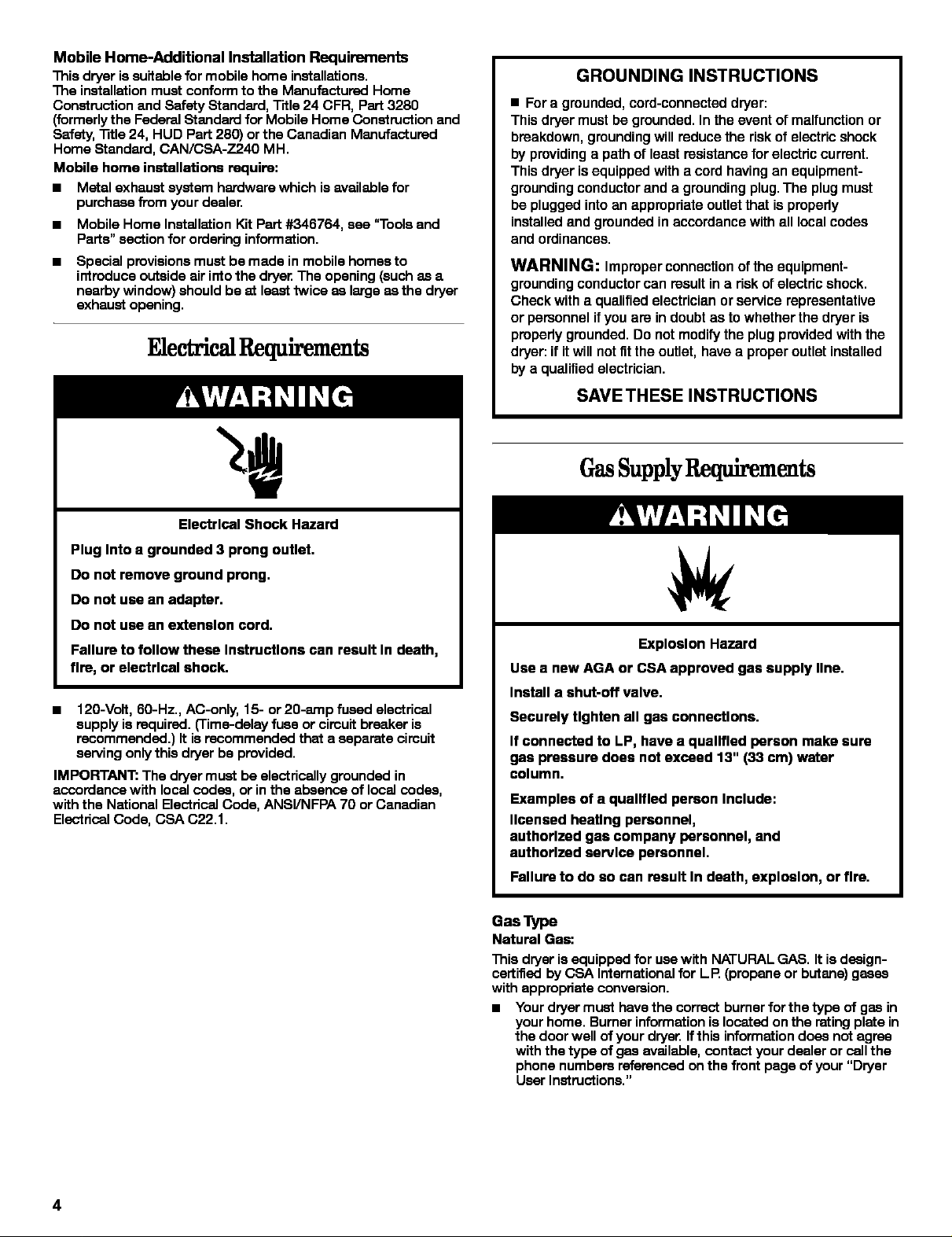
FAeetri qulrements
GROUNDING INSTRUCTIONS
• Fora grounded, cord-connected dryer:
This dryer must be grounded. In the event or malfunction or
breakdown, grounding will reduce the risk of electric shock
by providing a path or least resistance for electric current.
This dryer is equipped with a cord having an equipment-
grounding conductor and a grounding plug. The plug must
be plugged into an appropriate outlet that is properly
installed and grounded in accordance with all local codes
and ordinances.
WARNING: Improper connection orthe equipment-
grounding conductor can result in a risk or electric shock.
Check with a qualified electrician or service representative
or pemonnnl if you are in doubt as to whether the dryer is
properly grounded. Do not modify the plug provided with the
dryer: if itwill not fitthe outlet, have a proper outlet installed
by a qualified electrician.
SAVE THESE INSTRUCTIONS
GasSupplyRequirements
Electrical Shock Hazard
Plug Into a grounded 3 prong outlet.
Do not remove ground prong.
Do not use an adapter.
Do not use an extension cord.
Failure to follow these Instructions can result In death,
fire, or electrical shock.
120-Volt, 60-Hz., AC-only, 15- or 20-amp fused electrical
supply is required. ('rime-delay fuse or circuit breaker is
recommended.) It is recommended that a separate circuit
serving only this dryer be provided.
IMPORTANT: The dryer must be electrically grounded in
accordance with local codas, or in the absence of local codas,
with the National Electrical Code, ANSI/NFPA 70 or Canadian
Electrical Code, CSA C22.1.
Explosion Hazard
Use a new AGA or CSA approved gas supply line.
Install a shut-off valve.
Securely tighten all gas connections.
If connected to LP, have a qualified person make sure
gas pressure does not exceed 13" (33 cm) water
column.
Examples of a qualified person Include:
licensed heating personnel,
authorlzad gas company personnel, and
authorlzad service personnel.
Failure to do so can result In death, explosion, or fire.
Gas Type
Natural Gas:
This dryer is equipped for use with NATURAL GAS. It isdasign-
certified by CSA International for LP (propane or butane) gases
with appropriate conversion.
• Your dryermuat have the corrsct burner for the type of gas in
your home. Burner information is located onthe rating plate in
the door well of your dryer. Ifthis information does nat agree
with the type of gas available, contact your dealer or cell the
phone numbers referenced on the front page of your "Dryer
User Instructions."
4
L.R gas convemion:
Convemion must be made by a qualified technician.
No attempt shall be made to convert the appliance from the gee
specified on the modal/serial rating plate for use with a different
gee without consulting the serving gee supplier.
IMPORTANT: The gee installationmust conform with local codes,
or inthe absence of local codes, with the National Fuel Gee Code,
ANSI Z223.1/NFPA 54 or the Canadian Natural Gee and Propane
Installation Code, CSA B149.1.
Gas Supply Line:
• 1_in.IPS pipeisrecommended.
• % in. approved tubing is acceptable for lengths under 20 ff
(6.1 m) if local codes and gee supplier permit.
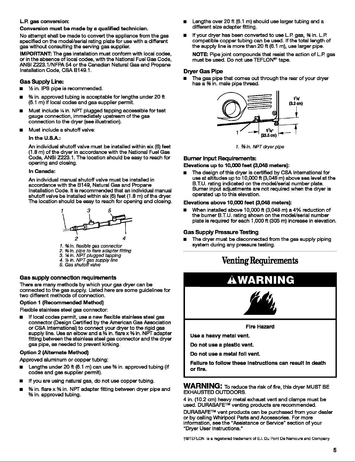
• Must include 1_in. NPT plugged tapping accessible for test
gauge connection, immediately upstream of the gee
connection to the dryer (see illustration).
• Must include a shutoff valve:
In the U.S.A.:
An individual shutoff valve must be installed within six (6)feet
(1.8 m) of the dryer in accordance with the National Fuel Gee
Code, ANSI Z223.1. The location should be eeey to reach for
opening and closing.
In Canada:
An individual manual shutoff valve must be installed in
accordance with the B149, Natural Gee and Propane
Installation Code. it isrecommended that an individualmanual
shutoff valve be installed within six (6) feet (1.8 m) of the dryen
The location should be easy to reach for opening end closing.
1 3 5
Lengths over 20 ft (6.1 m) should use largertubing and a
different size adapter fitting.
Ifyour dryer has been converted to use L.P gas, _ in. L.P
compatible copper tubing can be used. Ifthe total length of
the supply line is more than 20 ft (6.1 m), use larger pipe.
NOTE: Pipe joint compounds that resistthe action of L.R gee
must be used. Do not use TEFLON_ tape.
Dryer Gas Pipe
• The gee pipe that comes out through the rear of your dryer
has a _ in. male pipe thread.
11_'
(3.2©m)
1. _,_in. NPT dryer pipe
Bumer Input Requirements:
Elevations up to 10,000 feet (3,048 meters):
• The design ofthis dryer iscertified by CSA International for
use at altitudes up to I g,0gg ft (3,048 m) above sea level st the
B.TU. rating indicated on the model/eeital number plate.
Burner input adjustments are not required when the dryer is
operated up to this elevation.
Elevations above 10,000 feet (3,048 meters):
• When installed above 1O,O00ft (3,048 m) a 4% reduction of
the burner B.T.U. rating shown on the model/serial number
plate is required for each 1,00Oft (305 m) increase in elevation.
2 4
1. _ in. flexible gas connector
2. _ in. pipe to flare adapter fiffing
3. _ in. NPT plugged tapping
4. _ in. NPT gas supply line
5. Gas shutoff valve
Gas supply connection requirements
There are many methods by which your gee dryer can be
connected to the gas supply. Listed here are some guidelines for
two different methods of connection.
Option 1 (Recommended Method)
Flexible stainless steel gas connector:
• If local codes permit, use a new flexible stainless steel gee
connector (Design Certified by the American Gas Association
or CSA International) to connect your dryer to the rigid gas
supply line. Use an elbow and a % in.flare x % in. NPT adapter
fitting between the stainless steel gee connector and the dryer
gee pipe, as needed to prevent kinking.
Option 2 (Alternate Method)
Approved aluminum or copper tubing:
• Lengths under 20 ff (6.1 m) can use % in. approved tubing (if
codes and gee supplier permit).
• Ifyou are usingnatural gas, do not use copper tubing.
• % in. flare x % in. NPT adapter f'itting between dryer pipe and
% in. approved tubing.
Gas Supply Pressure Testing
• The dryer must be disconnected from the gee supply piping
system during any pressure testing.
VentingRequirements
Fire Hazard
Use a heavy metal vent.
Do not use a plaatlc vent.
Do not use a metal foil vent.
Failure to follow these Inatructlons can result In death
or fire.
WARNING: To reduca the risk of fire, this dryer MUST BE
EXHAUSTED OUTDOORS.
4 in. (10.2 cm) heavy metal exhaust vent and clamps must be
used. DURASAFETM venting products are recommended.
DURASAFETM vent products can be purchased from your dealer
or by calling Whirlpool Parts and Accessories. For more
information, see the "Assistance or Service" section of your
"Dryer User Instructions."
t®TEFLON is a registered trademark of E.I. Du Pont De Nernoure and Company
• The dryer exhaust must not be connected into any gas vent, Standard exhaust installation with rigid metal or flexible
chimney, wail, ceiling, ora concealed space of a building, metal vent
• Do not use an exhaust hood with a magnetic latch.
• Do not installflexible metal vent inenclosed wails, ceilings or
floors.
Use clamps to seal alljoints. Exhaust vent must not be
connected or secured with screws or other fastening devices
which extend intothe interior of the duct. Do not use duct
tape.
IMPORTANT: Observe all governing codas and ordinances.
Improper venting can cause moisture and lint to collect
Indoors, which may result In:
• Moisture damage to woodwork, furniture, paint, wail-
paper, carpets, etc.
Altemate installations for close clearances
Venting systems come in many varistias, Select the type best for
your installation. Two close-clearance installations are shown,
Referto the manufacturer's instructions,
• Housecleaning problems and health problems.
Use a heavy metal vent. Do not use plastic or metal foil vent.
Rigid metal vent isrecommended to prevent crushing and kinking.
Flexible metal vent must be fullyextended and supported when
the dryer is in itsfinal position. Remove excess flexible metal vent
to avoid sagging and kinking that may result in reduced airflow
and poor performance.
An exhaust hood should cap the vent to prevent rodents and
insects from entering the home.
Exhaust hood must be at least 12 in. (30.5 cm) from the ground or
any object that may be inthe path of the exhaust (such asflowers,
rocks or bushes, etc.).
If using an existing vent system, clean lint from the entire lengthof
the system and make sure exhaust hood is not plugged with lint.
Replace any plastic or metal foil vent with rigid metal or flexible
metal vent.
1. Over-The- Topinstallation (also available with one
offset elbow)
2. Periscope instailation
NOTE: The following kits for close clearance alternate installations
are available for purchase. Please reference the "Assistance or
Service" section of your "Dryer User Instructions."
• Over-The-Top Installation:
1 2
Part Number 4396028
PlanVentSystem
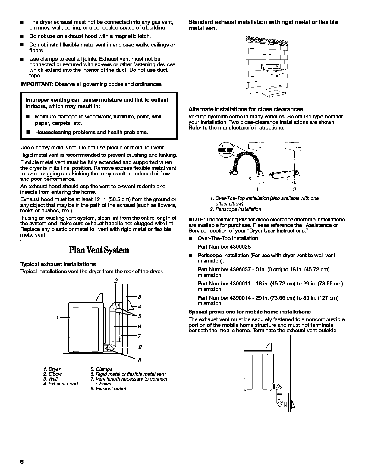
Typical exhaust installations
Typicalinstallationsventthe dryerfromtherearofthe dryer,
2
• Periscope Installation (For use with dryer vent to wall vent
mismatch):
Part Number 4396037 - Oin. (0 cm) to 18 in. (45.72 cm)
mismatch
Part Number 4396011 - 18 in. (45.72 cm) to 29 in. (73.66 cm)
mismatch
Part Number 4396014 - 29 in. (73.66 cm)to 50 in. (127 am)
mismatch
Special provisions for mobile home installations
1 I
The exhaust vent must be securely fastened to a noncombustible
portion of the mobile home structure and must notterminate
beneath the mobile home. Terminate the exhaust vent outside.
1. Dryer
2. Elbow
3. Wail
4. Exhaust hood
5. Clamps
6. Rigid metal or flexible metal vent
Z Vent length necessary to connect
elbows
8, Exhaust outlet
6
 Loading...