


Whirlpool LGV4634JT0, LGV4634JQ0 Installation Guide
Havequestionsaboutyourdryer?
Check your Use and Care Guide for a toll-free number to call, or call your
dealer. The dealer islisted in the Yetlow Pages of your phone directory
under "Appliances -- Household -- Major -- Service and Repair."
When you call, you will need the dryer model number and serial number.
Both numbers are on the model/serial rating plate located in the door well
b_hind the dryer door and on front of opening.
Record the numbers here for handy reference:
Model No.
Serial No.
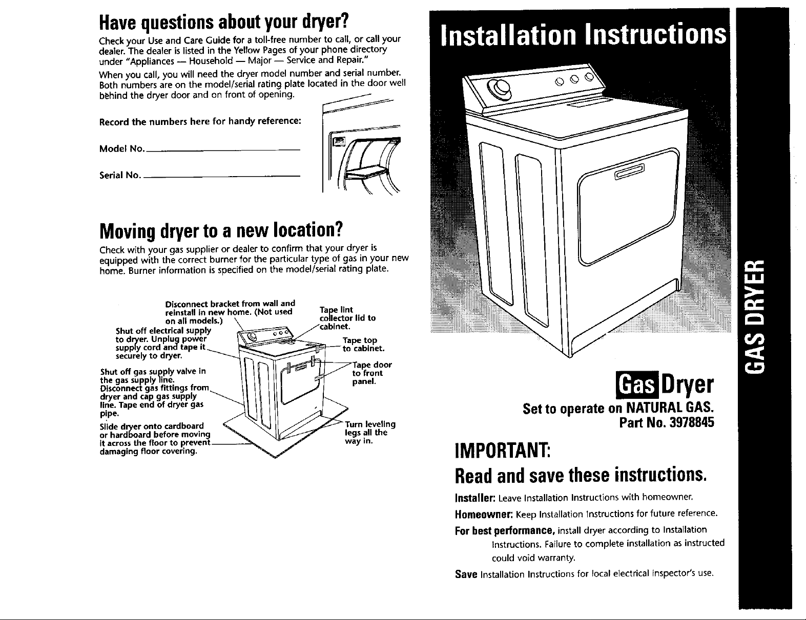
Movingdryerto a newlocation?
Check with your gas supplier or dealer to confirm that your dryer is
equipped with the correct burner for the particular type of gas in your new
home. Burner information is specified on the model/serial rating plate.
Disconnect bracket from wall and
reinstall in new home. (Not used
on all models.)
Shut off electrical supply
securely to dryer.
Shut off gas supply valve in
the gas supply fine.
Disconnect gas fittings from
dryer and cap gas supply
line. Tape end of dryer gas
pipe.
Slide dryer onto cardboard
or hardboard before moving
it across the floor to prevent--
damaging floor covering.
Tape lint
collector lid to
font
panel.
legs all the
way in.
[' Dryer
Set to operate on NATURALGAS.
Part No. 3978845
IMPORTANT:
Readandsavetheseinstructions.
Jnsta|Jer: Leave Installation Instructions with homeowner.
Hfimeowller: Keep Installation Instructions for future reference.
For best performance, install dryer according to Installation
Instructions. Failure to complete installation as instructed
could void warranty.
Save Installation Instructions for local electrical inspector's use.
-- Donotstoreorusegasoline,
--WHAT TODOIFYOUSMELL
r inlet "-.
_e connection
*from floor with _ 'Most installations will
dryer feet require at least S'inch
extended 1 inch dryer for the dryer vent.
clearance behLnd the
Forproperdryingperformance:
The location must provide:
I/Protection from weather and water: Do not
store or use dryer where it will be exposed to
water and weather.
I/Room temperature above 4S°F: If room
temperature is below 4S°F, automatic cycles
may not shut off.
I/Level floor: Maximum slope under entire dryer
shouid not be more than 1 inch. (If slope is
greater than 1 inch, install Extended Dryer Feet
Kit, Part No. 279810.) Clothes may not tumble
propeby and automatic sensor cyclesmay not
operate correctly if dryer is not level.
Itisyourresponsibilityto:
I/Observe all governing
codes and ordinances.
I/Check code requirements:
Some codes limit or do not
permit installation of clothes
dryers in garages, closets,
mobile homes or sleeping
quarters. Contact your local
building inspector.
Recessedarea]closetinstallation
Installation clearances.
Use recommended clearance for easier
installation.
Exhausted
Recessed
Closet
No other fuel burning appliance may be
installed in the same closet or recessed area.
• If codes permit, dryer may be installed in a
recessed area or closet using dimensions
shown.
• Dimensions are in inches and are the
minimum allowable. Detailed space
requirements can also be found on the label
on the back panel of the dryer. These
requirements ensure minimum clearances to
combustible construction, and prevent
blockage of air into the combustion chamber.
• Additional spacing should be considered for
ease of installation and servicing. Companion
appliance spacing should also be considered.
Doorclearance
Location must be large enough to fully open dryer door.
I/Comply with the installation
specifications and
dimensions.
I/Consider spacing
requirements for companion
appliances.
I/Make sure you have
everything necessary for
proper installation.
Recessed area installation
****** Wall, door and floor molding may require
WARNING:Foryoursafetythe
informationinthismanualmust
befollowedto minimizethe
riskoffireorexplosionorto
preventpropertydamage,
personalinjuryordeath.
orotherflammablevaporsand
liquidsinthevicinityofthisor
anyotherappliance.
GAS:
• Donottrytalightany
appliance.
Keep flammable materials and vapors, such as gasoline, away from dryer.
Place dryer at least 18 inches above the floor for a garage installation.
Failure to do so can result in death, explosion,or fire.
I/Properly install dryer.
I/Contact a qualified installer
to insure that the electrical
and gas installations meet all
national and local codes and
ordinances.
I/Exhaust to outdoors: Dryer
must be exhausted outdoors
to prevent exposure to
harmful substances in the gas
fuels.
frontview
18"
additional spacing.
• Donottouchanyelectrical
switch;donotuseanyphone
inyourbuilding.
• Cleartheroom,buildingor
areaofalloccupants.
• Immediatelycallyourgas,
supplierfromaneighbor's
phone.Followthegas
suppliersinstructions.
• Ifyoucannotreachyourgas
supplier,callthefire
department.
-- Installationandservicemust
bedonebyaqualified
installer,serviceagencyor
the9assupplier.
Explosion Hazard
v'Sturdy floor to support dryer weight of
175 pounds.
This installation must also conform with the
American National Standard, National Fuel
Gas Code ANSI Z223,1 -- latest edition***,
and all local codes and ordinances.
Copies of the standards listed may be obtained
from:
***American Gas Association
1515 Wilson Boulevard
Arlington, Virginia 22209
Closel]confined area installation
If a closetdoor isinstalled: The minimum
unobstructedair openings are required.
Louvered doors with equivalent air openings
are acceptable.
front view
closet d mdx
dOOr
3"
**** Minimum top and bottom air openings for
closet door.
*****External exhaust elbow requires additional
space.
8.1/4"
,., ,,
side view
I 14"
Electrical Shock Hazard
Pluginto a grounded3-prong outlet.
Do not removegroundprong.
Do not usean adapter.
Do not usean extensioncord.
Failureto followtheseinstructionscan
resultin neath,fire,or electricalshock.
Explosion Hazard
Use a new AGA approved gas supply
line.
Install a shut-off valve.
Securely tighten all gas connections.
U connected to LP, have a qualified
person make sure gas pressure does
not exceed 13" water column.
Examples of a qualified person
include licensed heating personnel,
authorized gas company personnel,
and authorized service personnel.
Failure to do so can result in death,
explosion, or fire.
OBSERVE ALL GOVERNING CODES AND
ORDINANCES.
Important: Observe all governing codes and
ordinances.
A 120-volt, 6O-Hz, AC-only, 15- or 2B-ampere
fused electrical supply is required. A time-delay
fuse or circuit breaker is recommended.
It is recommended that a separate circuit serving
only this appliance be provided.
If codes permit and a separate ground wire is
used, it is recommended that a qualified
electrician determine that the ground path is
adequate,
WARNING - Improper connection of the
equipment-grounding conductor can result in
a risk of electric shock. Check with a qualified
electrician or serviceman it you are in doubt
as to whether the appliance is properly
grounded. Do not modify the plug provided
with the appliance - if it will not fit the outlet,
have a proper outlet installed by a qualified
electrician.
3 prong ground-type
3-pron
groun_
Recommendedground
power
method
GROUNDING INSTRUCTIONS: This appliance
must be grounded. In the event of malfunction
or breakdown, grounding will reduce the risk of
electric shock by providing a path of least
resistance for electric current,
The power supply cord plug must be plugged
into an appropriate outlet that is properly
installed and grounded in accordance with all
local codes and ordinances.
Gasrequirements: Supplyline requirements:
Check that dryer is
equipped with the correct
burner for the particular
type or gas in the home.
Burner information will be
found on the model/serial
rating plate in door well of
the dryer. If this information
does not agree with the type of gas available,
see your dealer.
Natural Gas:
This dryer is equipped for use with NATURAL
GAS. It is design-certified by American Gas
Association for L.R (propane or butane) gases
with appropriate conversion.
L,R Gas:
No attempt shall be made to convert the
appliance from the gas specified on the
model/serial rating plate for use with a different
gas without consulting the serving gas supplier.
Conversion must be done by a qualified
service technician. Gas conversion kit part
numbers are listed on the gas valve burner
base.
Burnerinputrequirements:
Elevations up to 10,000 feet:
The design of this dryer has been certified by
the A.G.A. for use at altitudes up to 10,000 feet
above sea level at the B.T.U. rating indicated on
the model/serial rating plate. Burner input
adjustments are not required when the dryer is
operated up to this elevation.
Elevations above 10,000 feet:
When installed above 10,OO0feet_ a four
percent (4%) reduction of the burner B.T.U.
rating shown on the model/serial rating plate is
required for each 1,000 foot increase in
elevation. For assistance installing dryer above
10,0go feet elevation, contact your serving gas
supplier.
Copies of the standards listed above may be
obtained from:
* National Fire Protection Association
Batterymarch Park
Quincy, Massachusetts 02269
Provide a rigid gas supply line to the dryer
location. When rigid pipe is used it should be
IJ2 inch IPS.When acceptable to the gas
supplier and local codes, 318-inch approved
tubing may be used for lengths under 20 feet.
For lengths over 20 feet, larger tubing should
be used. Pipe-joint compounds resistant to
the action of L.P.gas must be used.
As__tmbinl_ttia°_ a(fn,PI.I_
the dryer.
If local codes permit, it
isrecommendedthat
new flexible metal
certified by the
American Gas
Association, be
tubing, design-
used for connecting
the appliance to the rigid red cap
gas supply line. (The gas
pipe which extends through the lower rear
of the appliance has 3/8-inch male pipe
thread.)
A 1/8-inch NPT plugged tapping, accessible
for test gauge connection, must be installed
immediately upstream of the gas supply
connection to the dryer.
The dryer and its individual shutoff valve
must be disconnected from the gas supply
piping system during any pressure testing
or that system at test pressures in excess of
1/2 psi.
The dryer must be isolated from the gas
supply piping system by closing its
individual manual shutoff valve during any
pressure testing of the gas supply piping
system at test pressures equal to or less
than 1/2 psi.
supply cord prong
shutoff valve
"open" position
to dryer _
Important: Observe all governing codes and
ordinances.
Dryer MUST BE EXHAUSTED to the outside,
Moisture and lint indoors may cause:
• lint to gather around the dryer where it can be
fuel for a fire.
• moisture damage to woodwork, furniture,
paint, wallpaper, carpet, etc,
• housecleaning problems and health problems.
Dura SafeTM venting products are
recommended and are available from your
dealer.
Fourdnch diameter vent is required.
Use a heavy metal vent. Do Not use plastic or
metal foil vent.
Rigid metal vent is recommended to prevent
crushing and kinking.
Flexible metal vent must be fully extended and
supported when the dryer is in
its final position. Remove excess --
flexible vent to avoid sagging
and kinking that may result in __
reduced air flow.
Fire Hazard
Use e heavy metal vent.
Do not use a plastic vent.
Do not use a metal foil vent.
Failure to do so can _esult in death or
fire.
DO Not use non metal flexible vent or
exhaust hoods with magnetic latches.
Metal exhaust vent must be four inches
in diameter.
Do Not exhaust dryer into a chimney,
furnace, cold air vent, attic or crawl space,
or any other vent used for venting.
Do Not install flexible vent in enclosed
walls, ceilings or floors,
An exhaust hood should cap
the exhaust vent to prevent
rodents and insects from
entering the home.
Exhaust outlet hood must be
at least 12 inches from the ground or any object
that may be in the path of the exhaust (such as
flowers, rocks or bushes, etc,),
If using an existing exhaust system, clean lint
from entire length of system and make sure
exhaust hood is not plugged with lint.
Replace any plastic or metal foil vent with rigid
metal or flexible metal vent.
Use clamps to seal all joints. Do Not use duct
tape, screws or other fastening devices that
extend into the interior of the vent to secure
vent.
Service check: Back pressure in any exhaust
system used must not exceed 0.6 inches in
water column measured with an incline
manometer at the point that exhaust vent
connects to dryer.
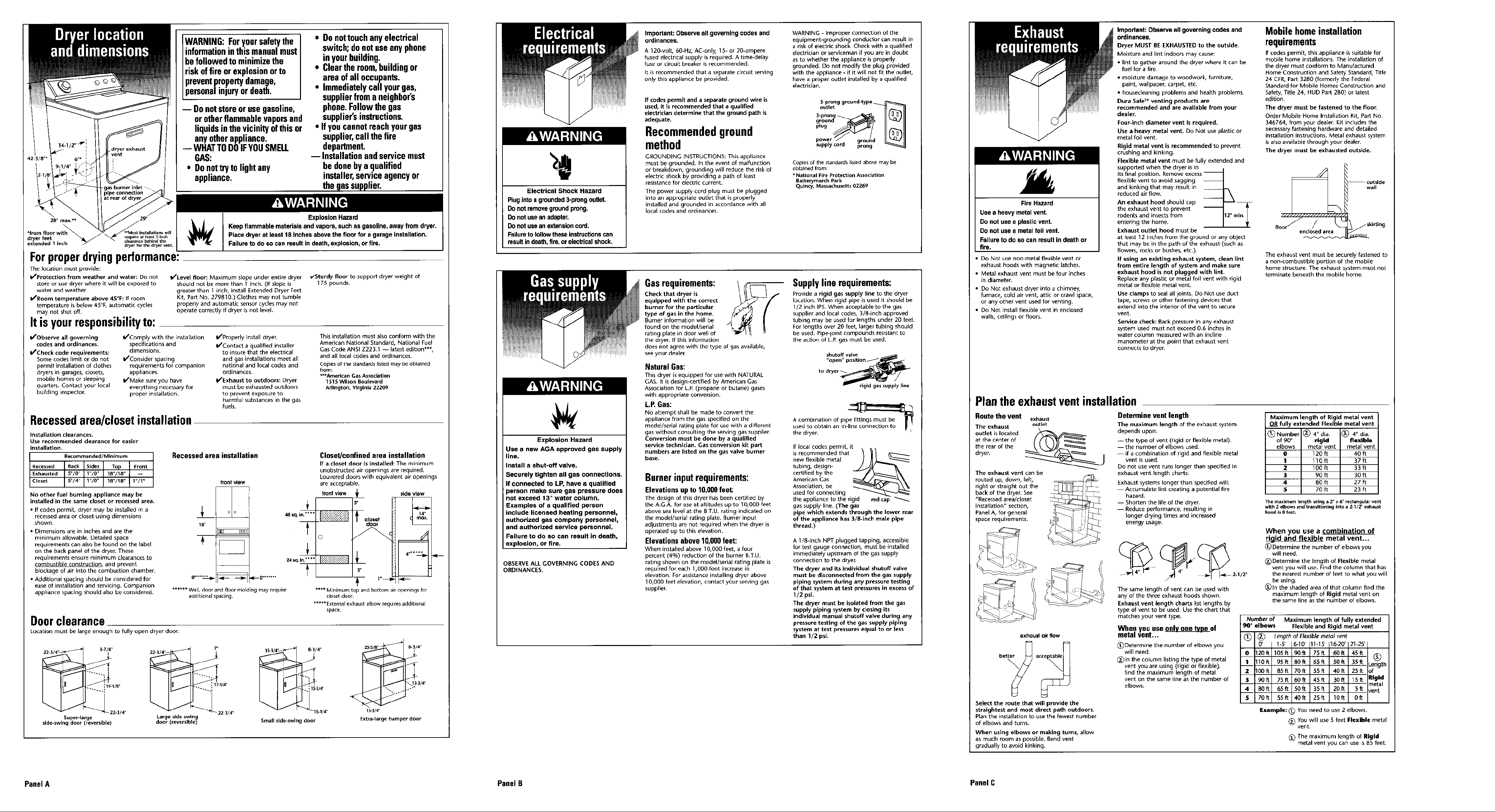
Plantheexhaustventinstallation
Route the vent
The exhaust
outlet is located
at the center of
the rear of the
dryer.
The exhaust vent can be
routed up, down, left,
right or straight out the
back of the dryer. See
"Recessedarea/closet
installation" section,
Panel A, for general
space requirements.
exhaust
outlet
exhoust tar flow
Determine vent length
The maximum length of the exhaust system
depends upon:
-- the type of vent (rigid or flexible metal).
-- the number of elbows used.
-- if a combination of rigid and flexible metal
vent is used.
Do not use vent runs longer than specified in
exhaust vent length charts.
Exhaust systems longer than specified will:
Accumulate lint creating a potential fire
hazard.
-- Shorten the life of the dryer.
-- Reduce performance, resulting in
longer drying times and increased
energy usage.
The same length of vent can be used with
any of the three exhaust hoods shown,
Exhaust vent length charts list lengths by
type of vent to be used. Use the chart that
matches your vent type.
When you use _of
metal vent...
_Determine the number of elbows you
will need.
(_ln the column listing the type of metal
vent you are using (rigid or flexible),
find the maximum length of metal
vent on the same line as the number of
elbows.
Mobile homeinstallation
requirements
If codes permit, this appliance is suitable for
mobile home installations. The installation of
the dryer must conform to Manufactured
Home Construction and Safety Standard, Title
24 CFR,Part 3280 (formerly the Federal
Standard for Mobile Homes Construction and
Safety, Title 24, HUD Part 280) or latest
edition.
The dryer must be fastened to the floor.
Order Mobile Home Installation Kit, Part No.
346764, from your dealer. Kit includes the
necessaryfastening hardware and detailed
installation instructions. Metal exhaust system
isalso available through your dealer.
The dryer must be exhausted outside.
wall
enclosed area
The exhaust vent must be securely fastened to
a non-combustible portion of the mobile
home structure. The exhaust system must not
terminate beneath the mobile home.
Maximum length of Rigid metal vent
OR fully extended Flexible metal vent
Number _ 4" din. @ 4" dia.
of 90° dboId flexible
elbows metal vent metal vent
O 120ft 4fill
1 110ff 37ft
2 1O0ft 33f_
3 90 ft 3Oft
4 80 ft 27 ft
$ 70 ft 23 ft
The maximum length using a 2" x 6" p_ctangular vent
with 2 elbows and transitioning into a 2-1/2" exhaust
hood is 8 feet.
When you use a combination of
rigid and flexible metal vent...
_)Determine the number of elbows you
will need.
_)Determine the length of Flexible metal
vent you will use. Find the column that has
the nearest number of feet to what you will
be using.
(_ln the shaded area of that column find the
maximum length of Rigid metal vent on
the same line as the number of elbows.
Number of Maximum length of fully extended
900 elbows Flexible and Rigid metal vent
O' 1-5' 6-10' 11-15' 16-20' 21-25'
2oft lOSft 9Oft 75R 6Oft 4Sft
i _l_l_d_O0ft 8Sff 70_ SSft 40ff 25ff of _"
80ft 6Sft SOft 35ft 2Oft 5ft vent
.... _ metal
Select the route that will provide the
straightest and most direct path outdoors.
Plan the installation to use the fewest number
of elbows and turns.
When using elbows or making turns, allow
as much room as possible, gend vent
gradually to avoid kinking,
side-swing door (reversible)
Super-large Large side swin
door (reverslble_
Small side-swing door
_15.1/4"
13-3/4 n
Extra-large hamper door
Panel A Panel B Panel C
Example: (_ You need to use 2 elbows.
(_ You will use S feet Flexlble metal
vent.
(_) The maximum length of Rlgld
metal vent you can use is 85 feet.