

Whirlpool LER3622PQ User Manual

240-VOLT ELECTRIC
COMPACT DRYER
Use & Care Guide
For questions about features, operation/performance,
parts, accessories or service, call: 1-800-253-1301.
or visit our website at...www
Table of Contents................................................. 2
.whirlpool.com
W10151595B
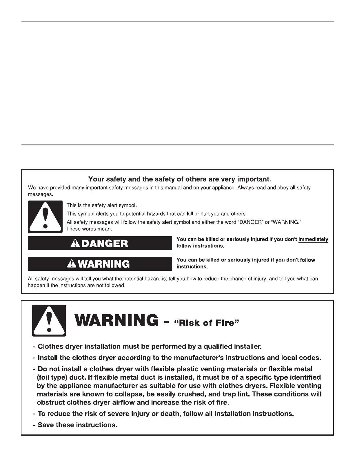
TABLE OF CONTENTS
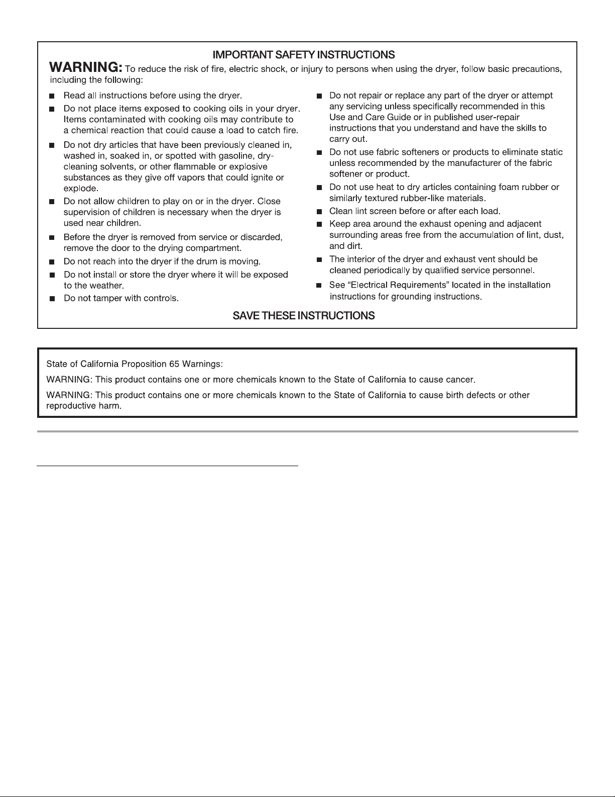
DRYER SAFETY.......................................................................... 2
INSTALLATION INSTRUCTIONS............................................... 3
Tools and Parts ............................................................................ 3
Location Requirements ............................................................... 4
Electrical Requirements ............................................................... 5
Electrical Connection ...................................................................6
Venting Requirements................................................................11
Plan Vent System .......................................................................12
Install Vent System.....................................................................12
Install Leveling Legs...................................................................13
Connect Vent..............................................................................13
Level Dryer .................................................................................13
Complete Installation .................................................................13
DRYER USE .............................................................................. 14
Starting Your Dryer.....................................................................14
DRYER SAFETY
Stopping and Restarting ............................................................15
Drying, Cycle, and Temperature Tips ........................................15
Cycles .........................................................................................15
DRYER CARE........................................................................... 15
Cleaning the Dryer Location.......................................................15
Cleaning the Lint Screen............................................................15
Cleaning the Dryer Interior .........................................................16
Removing Accumulated Lint......................................................16
Vacation and Moving Care.........................................................16
TROUBLESHOOTING............................................................... 17
ASSISTANCE OR SERVICE...................................................... 19
Accessories ................................................................................19
WARRANTY...............................................................................20
2
INSTALLATION INSTRUCTIONS
Tools and Parts
Tools needed
Gather the required tools and parts before starting installation. Read and follow the instructions provided with any tools listed here.
■ Flat-blade screwdriver
■ #2 Phillips screwdriver
■ Adjustable wrench
■ Wire stripper (direct wire
■ Level
■ 1/4" nut driver
installations)
■ Vent c la mps
■ Caulking gun and
compound (for installing
new exhaust vent)
■ Tin snips (new vent
installations)
■ Wood block
Parts supplied
Remove parts package from the dryer drum. Check that all parts listed are included.
■ 1 - Cycle Control (timer) knob
■ 1 - Push to Start button
■ 4 - Leveling legs
Parts needed
Check local codes, existing electrical supply and venting, and see “Venting Requirements” and “Electrical Requirements” before purchasing parts.
Mobile home installations require
■ Metal exhaust system hardware. For information on ordering,
please refer to the “Assistance or Service” section. You may
also contact the dealer from whom you purchased your dryer.
3
Location Requirements
)
)
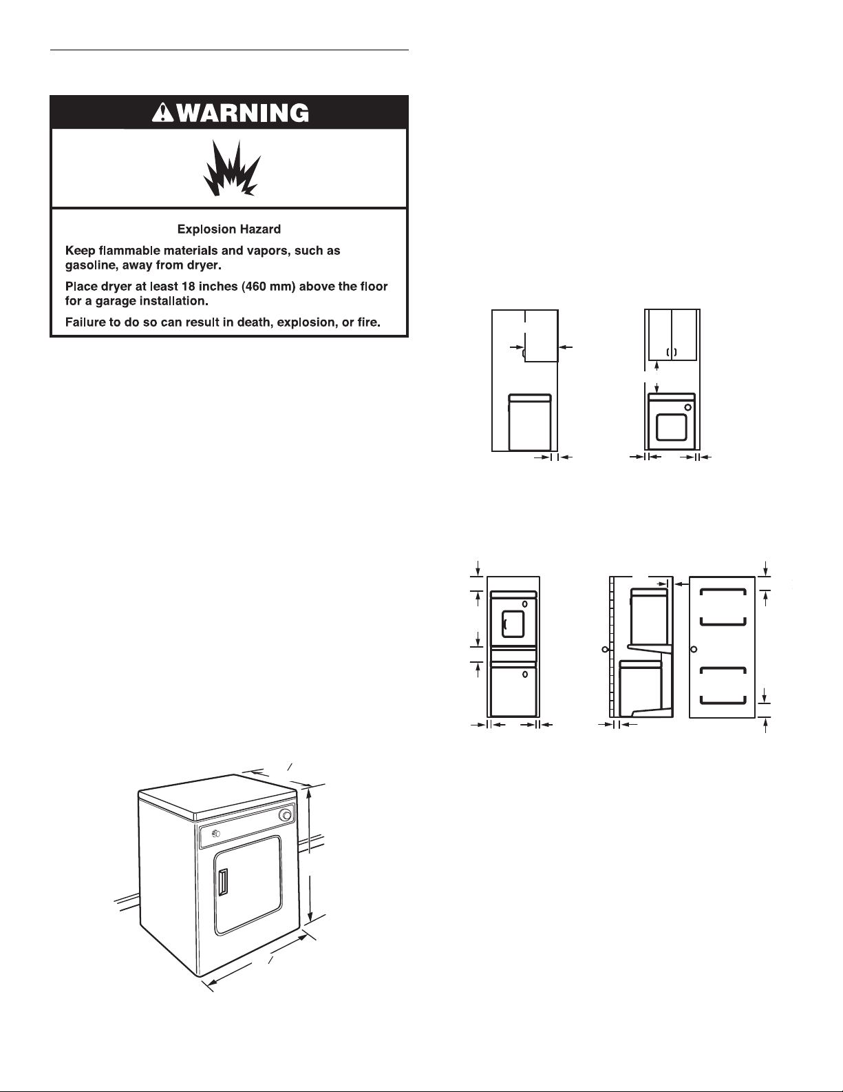
Minimum spacing for recessed area and closet installation
The following dimensions shown are for the minimum spacing allowed when the dryer is to be operated with, or without, the Stack Stand Kit. To purchase a Stack Stand Kit, see “Assistance or Service.”
■ Additional spacing should be considered for ease of
installation and servicing.
■ Additional clearances might be required for wall, door, and
floor moldings.
■ For closet installation with a door, minimum ventilation
openings in the top and bottom of the door are required.
Louvered doors with equivalent ventilation openings are
acceptable.
■ Companion appliance spacing should also be considered.
Recessed or closet installation - Dryer only
14"*
(356 mm)
You will need
■ A location that allows for proper exhaust installation. See
“Venting Requirements.”
■ A separate 30-amp circuit.
■ A grounded electrical outlet located within 2 ft (610 mm) of
either side of the dryer. See “Electrical Requirements.”
■ A sturdy floor to support the dryer weight (dryer and load)
of 115 lbs (52 kg). The combined weight of a companion
nce should also be considered.
applia
■ A level floor with a maximum slope of 1" (25 mm) under
entire dryer.
Do not operate your dryer at temperatures below 45ºF (7ºC).
At lower temperatures, the dryer might not shu
t off at the end
of an automatic cycle. Drying times can be extended.
The dryer must not be installed or stored in an area where it will
be exposed to water and/or weather.
Check code requirements. Some cod
installation of the dryer in garages, closets, mobile
es limit, or do not permit,
homes, or
sleeping quarters. Contact your local building inspector.
Installation Clearances
The location must be large enough to allow the dryer door to open fully.
Dryer Dimensions
3
20
4
"
*
(527 mm)
18"* (457 mm)
3"*
(76 mm)
A B
1"
(25 mm)
A. Side view - closet or confined area
B. Recessed area
Recessed or closet installation - Stacked
12"*
(305 mm)
12"*
(305 mm)
1"
(25 mm)
DRYER
WASHER
1"
(25 mm)
1"*
(25 mm)
A B
A. Recessed area
B. Side view - closet or confined area
C. Closet door with vents
3"*
(76 mm)
1"
(25 mm)
2
48 in. *
(309.7 cm )
2
24 in. *
(154.8 cm )
C
2
2
3"*
(76 mm
3"*
(76 mm
†
31"
(787 mm)
7
23
8
"
(606 mm)
*Most installations require a minimum 5½" (140 mm) clearance
behind the dryer for the exhaust vent with elbows. See “Venting
Requirements.”
4
Mobile Home - Additional Location Requirements
This dryer is suitable for mobile home installations. The
installation must conform to the Manufactured Home
Construction and Safety Standard, Title 24 CFR, Part 3280
(formerly the Federal Standard for Mobile Home Construction
and Safety, Title 245, HUD Part 280).
Mobile home installations require:
■ Metal exhaust system hardware, which is available for
purchase from your dealer.
■ Special provisions must be made in mobile homes to
introduce outside air into the dryer. The opening (such as a
nearby window) should be at least twice as large as the dryer
exhaust opening.
Electrical Requirements
It is your responsibility
■ To contact a qualified electrical installer.
■ To be sure that the electrical connection is adequate and in
conformance with the National Electrical Code, ANSI/NFPA
70-latest edition and all local codes and ordinances.
The National Electrical Code requires a 4-wire supply
conn
ection for homes built after 1996, dryer circuits involved
in remodeling after 1996, and all mobile home installations.
A copy of the above code standards can be obtained from:
ional Fire Protection Association, One Batterymarch Park,
Nat
Quincy, MA 02269.
■ To supply the required 3 or 4 wire, single phase, 120/240 volt,
60 Hz., AC only electrical supply (or 3 or 4 wire, 120/208 volt
ele
ctrical supply, if specified on the serial/rating plate) on a
separate 30-amp circuit, fused on both sides of the line. A
time-delay fuse or circuit breaker is recommended. Connect
to an individual branch circuit. Do not have a fuse in the
neutral or grounding circuit.
■ Do not use an extension cord.
■ If codes permit and a separate ground wire is used, it is
recommended that a qualified electrician determine that
the ground path is adequate.
Electrical Connection
To properly install your dryer, you must determine the type of electrical connection you will be using and follow the instructions provided for it here.
■ If local codes do not permit the connection of a neutral
ground wire to the neutral wire, see “Optional 3-wire
connection” in the “Electrical Connection” section.
■ This dryer is manufactured ready to install with a 3-wire
electrical supply connection. The neutral ground wire is
permanently connected to the neutral conductor (white wire)
within the dryer. If the dryer is installed with a 4-wire electrical
supply connection, the neutral ground wire must be removed
from the external ground conductor screw (green screw), and
secured under the neutral terminal (center or white wire) of
the terminal block. When the neutral ground wire is secured
under the neutral terminal (center or white wire) of the
terminal block, the dryer cabinet is isolated from the neutral
conductor.
■ A 4-wire power supply connection must be used when the
appliance is installed in a location where grounding through
the neutral conductor is prohibited. Grounding through the
neutral is prohibited for (1) new branch-circuit installations,
(2) mobile homes, (3) recreational vehicles, and (4) areas
where local codes prohibit grounding through the neutral
conductors.
If using a power supply cord:
Use a UL listed power supply cord kit marked for use with
clothes
■ A UL listed 30-amp power supply cord, rated
■ A UL listed strain relief.
dryers. The kit should contain:
120/240 volt minimum. The cord should be type SRD
SRDT and be at least 4 ft (1.22 m) long. The wires that
connect to the
dryer must end in ring terminals or spade
terminals with upturned ends.
or
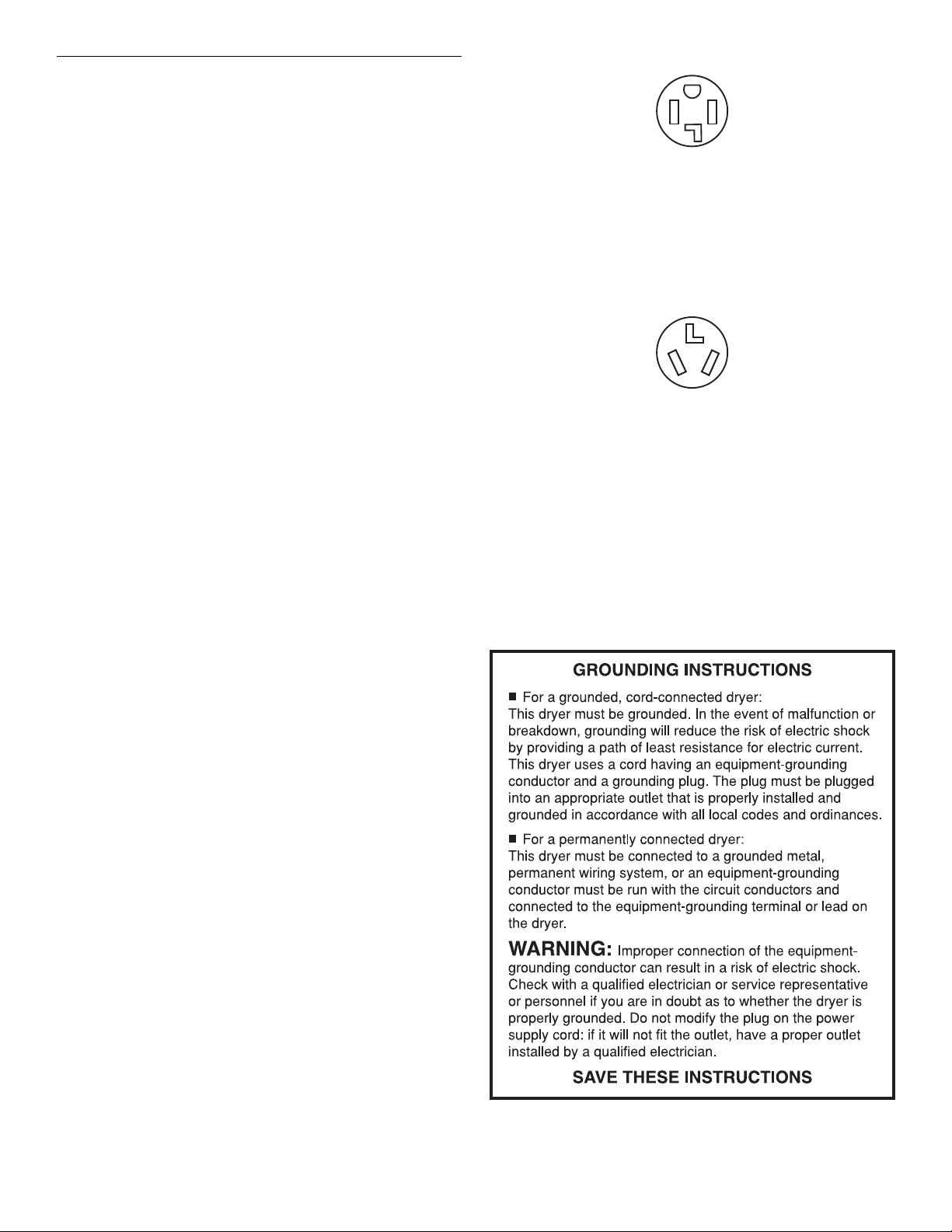
If your outlet looks like this:
4-wire receptacle (14-30R)
Then choose a 4-wire power supply cord with ring or spade
terminals and UL listed strain relief. The 4-wire power supply
cord, at least 4 ft (1.22 m) long, must have four 10-gauge
copper wires and match a 4-wire
receptacle of NEMA Type
14-30R. The ground wire (ground conductor) may be either
green or bare. The neutral conductor must be
identified by a
white cover.
If your outlet looks like this:
3-wire receptacle (10-30R)
Then choose a 3-wire power supply cord with ring or spade terminals and UL listed strain relief. The 3-wire power supply cord, at least 4 ft (1.22 m) long, must have three 10-gauge copper wires and match a 3-wire receptacle of NEMA Type 10-30R.
If connecting by direct wire:
Power supply cable must match power
supply (4-wire or 3-wire)
and be:
■ Flexible armored cable or nonmetallic sheathed copper cable
(with ground wire), protected with flexible metallic conduit.
All current-carrying wires must be insulated.
■ 10-gauge solid copper wire (do not use aluminum).
■ At least 5 ft (1.52 m) long.
5
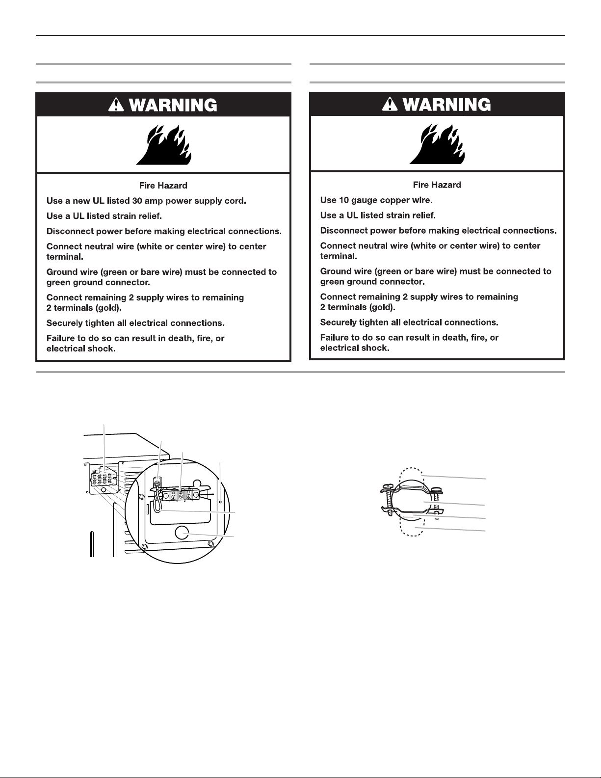
Electrical Connection
A
E
F
A
C
Power Supply Cord Direct Wire
1. Disconnect power.
move the hold-down screw and terminal block cover.
2. Re
3. Install strain relief.
B
C
A. Terminal block cover
B. External ground conductor screw
C.
Center terminal
D. Hold-down scre
E. Neutral ground wire
F. Hole below terminal block opening
block screw
w location
Style 1: Power supply cord strain relief
■ Remove the screws from a 3/4" (19 mm) UL listed strain
relief (UL marking on strain relief). Put the tabs of the two
clamp sections into the hole below the terminal block
opening so that one tab is pointing up and the other is
pointing down, and hold in place. Tighten strain relief
screws just enough to hold the two clamp sections
D
together.
B
D
A. Strain relief tab pointing up
B. Hole below terminal block opening
C. Clamp section
D. Strain relief tab pointing down
6
 Loading...