

Whirlpool LER3622HQ Use and Care Guide
240-VOLTELECTRIC
COMPACTDRYER
Use&CareGuide
For questions about features, operation/performance,
parts accessories or service, call: 1-800-253-1301
or visit our website at www.whirlpool.com
Table of Contents.................................................................2
3406878
TABLEOFCONTENTS
DRYER SAFETY .......................................................................... 3
INSTALLATION INSTRUCTIONS ............................................... 4
Tools and Parts ............................................................................ 4
Location Requirements ............................................................... 4
Electrical Requirements ............................................................... 6
ElectricalConnection ................................................................... 7
Venting Requirements ................................................................ 11
PlanVent System ....................................................................... 12
InstallVent System ..................................................................... 13
Install Leveling legs ................................................................... 13
Level Dryer ................................................................................. 14
Connect Vent.............................................................................. 14
Complete InstsJlstion................................................................. 14
DRYER USE .............................................................................. 15
Starting Your Dryer..................................................................... 15
Stopping and Restarting ............................................................ 15
Loading....................................................................................... 16
Drying, Cycle, and Temperature Tips ........................................ 16
Cycles ......................................................................................... 16
DRYER CARE ........................................................................... 17
Cleaning the lint Screen ............................................................ 17
Cleaning the Dryer Interior ......................................................... 17
Removing Accumulated Lint...................................................... 17
Vacation and Moving Care......................................................... 17
TROUBLESHOOTING ............................................................... 18
ASSISTANCE OR SERVICE ..................................................... 19
WARRANTY .............................................................................. 20
2
DRYER SAFETY
Your safety and the safety of others are very important.
We have provided many important safety messages in this manual and on your appliance. Always read and obey all
safety messages.
This isthe safety alert symbol.
This symbol alertsyou to potential hazards that can Idllor hurt you and others.
All safety messages will follow the safety alert symbol and either the word "DANGER" or
"WARNING." These words mean:
You can be killed or seriously injured if you don't
immediately follow instructions.
You can be killed or seriously injured if you don't
follow instructions.
All safety messages will tell you what the potential hazard is, tell you how to reduce the chance of injury, and tell you
what can happen ifthe instructionsare not followed.
IMPORTANT SAFETY INSTRUCTIONS
WARNING: To reduce the riskof fire, electric shock, or injury to personswhen using the dryer, follow basic
precautions, including the following:
• Read all instructions before using the dryer.
• Do not place items exposed to cooking oils in
your dryer. Items contaminated with cooking oils
may contribute to a chemical reaction that could
cause a load to catch fire.
• Do not dry articles that have been previously
cleaned in, washed in, soaked in,or spotted with
gasoline, dry-cleaning solvents, other flammable,
or explosive substances as they give off vapors
that could ignite or explode.
• Do not allow children to play on or in the dryer.
Close supervision of children is necessary when
the dryer is used near children.
• Beforethe dryer is removed from service or dis-
carded, remove the door to the dryingcompart-
ment.
• Do not reach into the dryer ifthe drum is moving.
• Do not install or store the dryer where it will be
exposed to the weather.
• Do not tamper with controls.
• Do not repair or replace any part of the dryer or
attempt any servicing unless specifically recom-
mended inthis Use and Care Guide or in published
user-repair instructionsthat you understand and have
the skillsto carry out.
• Do not use fabric softeners or products to eliminate
static unless recommended by the manufacturer of
the fabric softener or product.
• Do not use heat to dry articles containing foam rubber
or similarlytextured rubber-like materials.
• Clean lintscreen before or after each load.
• Keep area around the exhaust opening and adjacent
surrounding areas free from the accumulation of lint,
dust, and dirt.
• The interiorof the dryer and exhaust vent should be
cleaned periodically by qualified service personnel.
• See installation instructions for grounding require-
ments.
SAVE THESE INSTRUCTIONS
INSTAIJATION
INSTRUCTIONS
ToolsandParts
Tools needed
Cheokthat you have everything necessary for correct installation.
Proper installation is your responsibility.
= Flat-bladed screwdriver
= #2 Phillips head
screwdriver
= Level
= Adjustable wrench
= 1/_in.nut driver
a Safety glasses (optional)
m Duct tape
= Wood block
= Caulking gun and
compound (for installing
new exhaust vent)
a Gloves (optional)
m Tin snips (new vent
installations)
LocationRequirements
Explosion Hazard
Keep flammable materials and vapors, such as
gasoline, away from dryer.
Place dryer at least 18 inches (46 cm) above the
floor for a garage installation.
Failure to do so can result in death, explosion,
or fire.
Parts supplied
Remove parts package from the dryer drum. Check that all parts
listed are included.
m 1 - Cycle Control (timer) knob
= 1 - Push to Start button
m 4 - Leveling legs
Parts needed
Check local codes, existing electrical supply and venting, and
sea "Venting Requirements" and "Electrical Requirements"
before purchasing parts.
Mobile home installations require
m Metal exhaust system hardware. For ordering information,
please refer to the "Assistance or Service" section of this
manual. You may also contact the dealer from whom you
purchased your dryer.
You will need
m A location that allows for proper exhaust installation. See
"Venting Requirements."
m A separate 30 amp circuit.
m A grounded electrical outlet located within 2 ft (61 ca) of
either side of the dryer.See "Electrical Requirements."
m A sturdy floor to support the dryer weight (dryer and load) of
115 Ibs (52 kg). The combined weight of a companion
appliance should also be considered.
m A level floor with a maximum slope of 1 in. (2.5 cm) under
entire dryer.
Do not operate your dryer at temperatures below 4,5°F (7°(3). At
lower temperaturss, the dryer might not shut off at the end of an
automatic cycle. Drying times can be extended.
Install the dryer where it is protected from water and/or weather.
Check code requirements. Some codes limit, or do not permit,
installation of the dryer in garages, closets, mobile homes, or
sleeping quarters. Contact your local building inspector.
Installation Clearances
Locationmust be largeenoughto fullyopendryerdoor.
4
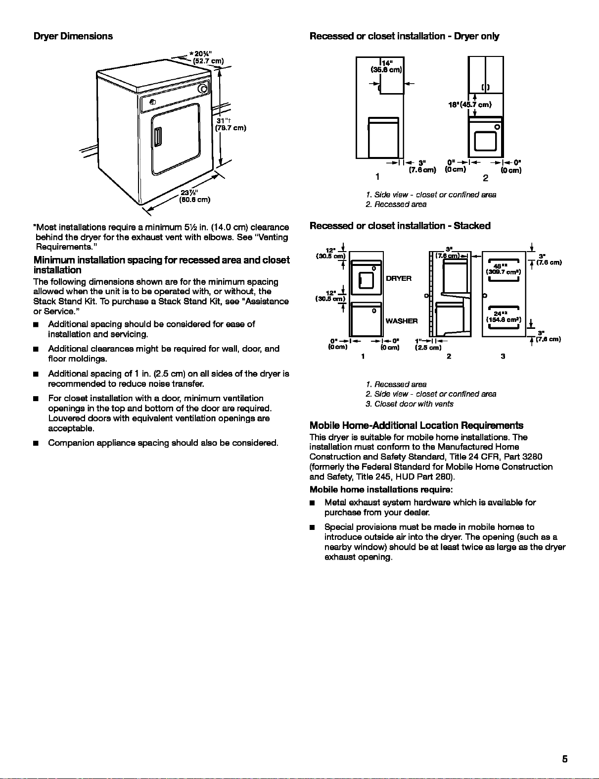
DryerDimensions
Recessed or closet installation - Dryer only
(35.6cm
(52.7 :m_
31"t
(78.7 cm)
*Most installations require a minimum 5½ in. (14.0 cm) clearance
behind the dryer for the exhaust vent with elbows. See "Venting
Requirements."
Minimum installation spacing for recessed area and closet
installation
The following dimensions shown are for the minimum spacing
allowed when the unit is to be operated with, or without, the
Stack Stand Kit. To purchase a Stack Stand Kit, see "Assistance
or Service."
= Additional spacing should be considered for ease of
installation and servicing.
= Additional clearances might be required for wall, door, end
floor moldings.
= Additional spacing of 1 in. (2.5 cm) on all sides ofthe dryer is
recommended to reduce noise transfer.
a
For closet installation with e door, minimum ventilation
openings in the top and bottom of the door are required.
Louvered doors with equivalent ventilation openings are
acceptable.
a Companion appliance spacing should also be considered.
18=(4_7 ¢m}
_,-I I_- 8"
1
1. Side view- closet or confined area
2. Recessed area
(7.6_1
(Ocm) (Ocm)
2
Recessed or closet installation - Stacked
12" _ --
0
DRYER
12" _
(30.5 m)
WASHER
I. Recessed area
2. Side view- closet or confined area
3. Closet doer with vents
4.-
(309.7 cm')
(1s4.8cn_)
48 =1=
24=±
Mobile Home-Additional Location Requirements
This dryer issuitable for mobile home installations, The
installation must conform to the Manufactured Home
Construction and Safety Standard, Title 24 CFR, Part 3280
(formerly the Federal Standard for Mobile Home Construction
and Safety, Title 245, HUD Part 280),
Mobile home installations require:
a Metal exhaust system hardware which isavailable for
purchase from your dealer,
a Special provisions must be made in mobile homes to
introduce outside air into the dryer. The opening (such as a
nearby window) should be at least twice as large as the dryer
exhaust opening.
±
3"
(7.6 cm)
±
3"
"(7.6 cm)
3
FAeetri c rernents
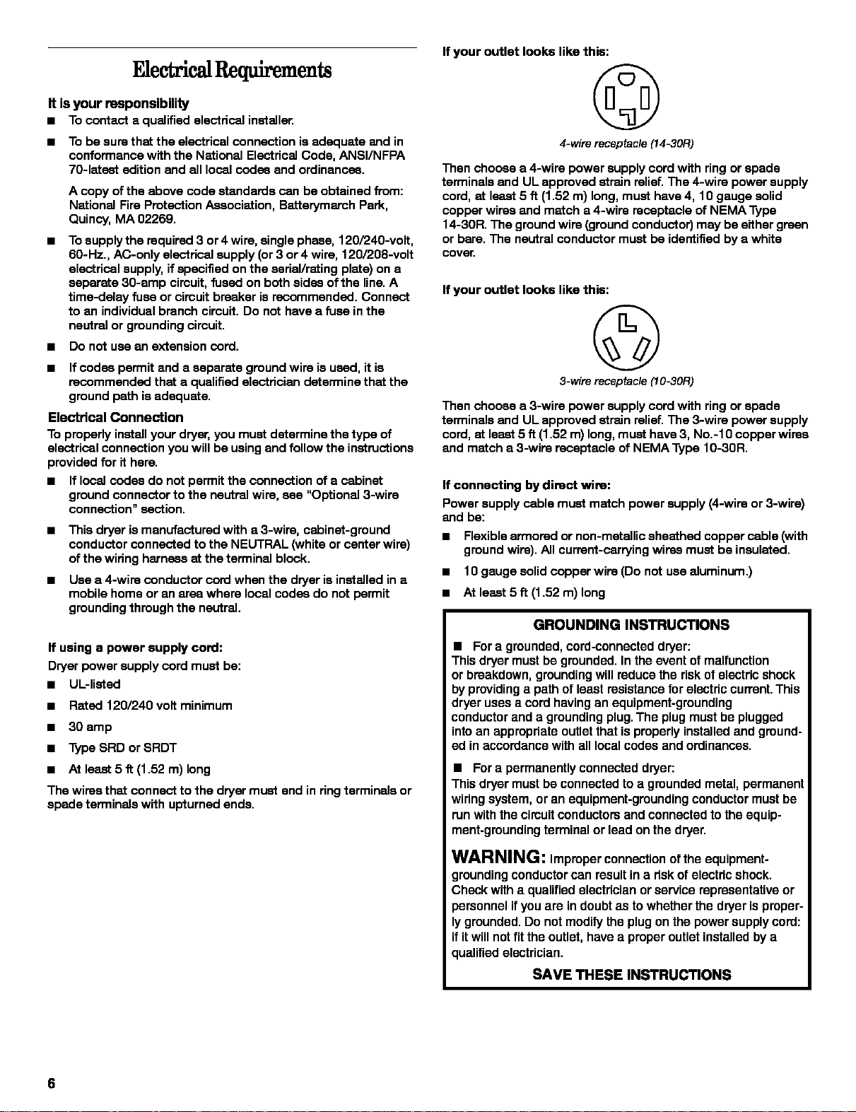
If your outlet looks like this:
It isyour responsibility
• Tocontacta qualifiedelectricalinstaller,
• To be sure that the electrical connection is adequate and in
conformance with the National Electrical Code, ANSI/NFPA
7O-latest edition and all local codes and ordinances.
A copy of the above code standards can be obtained from:
National Fire Protection Association, Batterymaroh Park,
Quincy, MA 02269.
• To supply the required 3 or 4 wire, single phase, 120/240-volt,
60-Hz,, AC-only electrical supply (or 3 or 4 wire, 120/208-volt
electrical supply, if specified on the esrial/rsting plate) on a
separate 30-amp circuit, fused on both sides ofthe line, A
time-delay fuse orcircuit breaker is recommended, Connect
to an individual branch circuit, Do not have a fuse in the
neutral or grounding circuit,
• Do not use an extension cord.
• If codes permit and a separate ground wire is used, it is
recommended that a qualified electrician determine that the
ground path is adequate,
Electrical Connection
To properly installyour dryer, you must determine the type of
electrical connection you will be using and follow the instructions
provided for it here,
• If local codes do not permit the connection of a cabinet
ground connector to the neutral wire, see "Optional 3-wire
connection" section,
• This dryer is manufactured with a 3-wire, cabinet-ground
conductor connected to the NEUTRAL (white or center wire)
of the wiring harness at the terminal block,
• Use a 4-wire conductor cord when the dryer is installed in a
mobile home or an ares where local codes do not permit
grounding through the neutral.
If using a power supply cord:
Dryer power supply cord must be:
• UL-listed
• Rated 120/240 volt minimum
• 30 amp
• Type SRD or SRDT
• At least 5 fl (1.52 m) long
The wires that connect to the dryer must end in ring terminals or
spade terminals with upturned ends.
©
4-wire receptacle(14-30R)
Then choose a 4-wire power supply cord with ring or spade
terminals and UL approved strain relief. The 4-wire power supply
cord, at least 5 ft (1.52 m) long, must have 4, 10 gauge solid
copper wires and match a 4-wire receptacle of NEMA Type
14-30R. The ground wire (ground conductor) may be either green
or bare. The neutral conductor must be identified by a white
cover.
If your outlet looks like this:
©
3-wire receptacle(10-30R)
Then choose a 3-wire power supply cord with ring or spade
terminals and UL approved strain relief. The 3-wire power supply
cord, at least 5 ft (1.52 m) long, must have 3, No.-10 copper wires
and match a 3-wire receptacle of NEMA Type 10-30R.
If connecting by direct wire:
Power supply cable must match power supply (4-wire or 3-wire)
and be:
• Flexible armored or non-mstallic sheathed copper cable (with
ground wire). All current-carrying wires must be insulated.
• I0 gauge solid copper wire (Do not use aluminum.)
• At least 5 ft (1.52 m) long
GROUNDING INSTRUCTIONS
• For a grounded, cord-connected dryer:
This dryer must be grounded. In the event of malfunction
or breakdown, grounding will reduce the risk of electric shock
by providing a path or least resistance for electric current. This
dryer uses a cord having an equipment-grounding
conductor and a grounding plug. The plug must be plugged
into an appropriate outlet that is properly installed and ground-
ed in accordance with all local codes and ordinances.
• For a permanenUy connected dryer:
This dryer must be connected to a grounded metal, permanent
wiring system, or an equipment-grounding conductor must be
run with the circuit conductors and connected to the equip-
ment-grounding terminal or lead on the dryer.
WARNING: Improper connection orthe equipment-
grounding conductor can result in a risk or electric shock,
Check witha qualified electrician or service representative or
personnel if you are indoubt as to whether the dryer is proper-
ly grounded, Do not modify the plug on the power supply cord:
if it will not fit the outlet, have a proper outlet installed by a
qualified electrician,
SAVE THESE INSTRUCTIONS
6
 Loading...