

Whirlpool KUIA15NRH'11, KUIA18NNJ'11, KUIA15PLL'11, KUIA18PNL'11, KUIA15NLH'11 User Manual
...
KAR-19
TECHNICAL EDUCATION
2007 DESIGN
15q & 18q AUTOMATIC
ICE MAKERS
KUIA15NRH*11
KUIA15PRL*11
KUIA15NLH*11
KUIA15PLL*11
* Denotes Color Designation
KUIA18NNJ*11
KUIA18PNL*11
Intoductory Models
JOB AID 4317408

FORWARD
This KitchenAid Job Aid “2007 Design 15" & 18" Automatic Ice Makers” (Part No. 4317408),
provides the In-Home Service Professional with information on the installation, operation, and
service of the 2007 Design 15" & 18" Automatic Ice Makers. For specifi c information on the model
being serviced, refer to the “Use and Care Guide,” or “Tech Sheet” provided with the ice maker.
The Wiring Diagram and Strip Circuits used in this Job Aid are typical and should be used for
training purposes only . Always use the Wiring Diagram supplied with the product when servicing
the ice maker.
GOALS AND OBJECTIVES
The goal of this Job Aid is to provide detailed information that will enable the In-Home Service
Professional to properly diagnose malfunctions and repair the KitchenAid 2007 Design 15" & 18"
Automatic Ice Makers.
The objectives of this Job Aid are to:
• Understand and follow proper safety precautions.
• Successfully troubleshoot and diagnose malfunctions.
• Successfully perform necessary repairs.
• Successfully return the ice maker to its proper operational status.
WHIRLPOOL CORPORA TION assumes no responsibility for any repairs made
on our products by anyone other than In-Home Service Professionals.
Copyright © 2007, Whirlpool Corporation, Benton Harbor, MI 49022
- ii -

TABLE OF CONTENTS
Page
GENERAL .............................................................................................................................. 1-1
Ice Maker Safety ................................................................................................................ 1-1
KitchenAid Model & Serial Number Designations .............................................................. 1-2
Model & Serial Number Label Location.............................................................................. 1-3
Specifi cations ..................................................................................................................... 1-4
INSTALLATION INFORMATION ............................................................................................ 2-1
Electrical Supply Requirements ......................................................................................... 2-1
Water Supply And Drain Connections ................................................................................ 2-2
THEORY OF OPERATION .................................................................................................... 3-1
Operating Systems............................................................................................................. 3-1
Operational Modes ............................................................................................................. 3-5
Models With Internal Drain Pumps..................................................................................... 3-8
COMPONENT ACCESS ........................................................................................................ 4-1
Component Locations ........................................................................................................ 4-1
Removing The Bin Thermistor, Cutter Grid, Evaporator Thermistor,
& Water Distributor ......................................................................................................... 4-2
Removing The Electronic Control Housing Components ................................................... 4-5
Removing The Water Recirculation Pump ......................................................................... 4-7
Removing The Reservoir Drain Pump & Water Level Sensor............................................ 4-8
Removing The Condenser Fan Motor ................................................................................ 4-9
Removing The Evaporator ............................................................................................... 4-12
Removing The Measured Fill Water Valve ....................................................................... 4-16
Removing The Hot Gas Valve & Solenoid ....................................................................... 4-17
Removing The Condenser ............................................................................................... 4-18
Removing The Compressor ............................................................................................. 4-19
Removing The Internal Drain Pump ................................................................................. 4-21
Removing The Ice Maker Door & Gasket (15" Models) ................................................... 4-22
Removing The Ice Maker Door & Gasket (18" Models) ................................................... 4-23
COMPONENT TESTING ........................................................................................................ 5-1
Bin Thermistor .................................................................................................................... 5-1
Evaporator Thermistor ....................................................................................................... 5-1
Cutter Grid.......................................................................................................................... 5-2
Dual Transformer ............................................................................................................... 5-2
Water Recirculation Pump ................................................................................................. 5-3
Reservoir Drain Pump ........................................................................................................ 5-3
Water Level Sensor ............................................................................................................ 5-4
Condenser Fan Motor ........................................................................................................ 5-4
Measured Fill Water Valve ................................................................................................ 5-5
Hot Gas Valve Solenoid ..................................................................................................... 5-5
Compressor, Overload Protector, & Relay ......................................................................... 5-6
- iii -

Page
DIAGNOSTICS & TROUBLESHOOTING ............................................................................. 6-1
Water And Its Effect On Making Ice ................................................................................... 6-1
Troubleshooting Chart ........................................................................................................ 6-2
Diagnostic Flow Chart For Ice Maker Control Board ......................................................... 6-5
WIRING DIAGRAM & STRIP CIRCUITS ............................................................................... 7-1
Wiring Diagram .................................................................................................................. 7-1
Strip Circuits ....................................................................................................................... 7-2
TECH TIPS ............................................................................................................................. 8-1
Cleaning The Ice Maker ..................................................................................................... 8-1
Cleaning The Evaporator Plate ....................................................................................... 8-1
- iv -
GENERAL
WARNING
DANGER
ICE MAKER SAFETY
Your safety and the safety of others are very important.
We have provided many important safety messages in this manual and on the appliance.
Always read and obey all safety messages.
This is the safety alert symbol.
This symbol alerts you to potential hazards that can kill or hurt you and others.
All safety messages will follow the safety alert symbol and either the word
“DANGER” or “WARNING.” These words mean:
You can be killed or seriously injured if you don’t
WARNING
DANGER
All safety messages will tell you what the potential hazard is, tell you how to reduce the chance
of injury, and tell you what can happen if the instructions are not followed.
immediately follow instructions.
You can be killed or seriously injured if you don’t
follow instructions.
1-1

KITCHENAID MODEL & SERIAL NUMBER DESIGNATIONS
MODEL NUMBER K UI A 15 NR H S 0
INTERNATIONAL SALES IND.
OR MARKETING CHANNEL
IF PRESENT
PRODUCT GROUP
K = KITCHENAID
PRODUCT IDENTIFICATION
UI = UNDERCOUNTER ICE MAKER
MERCHANDISING SCHEME
A = ARCHITECT C = CULINARY & ARCHITECT II
S = STANDARD O = OUTDOOR
V = SIGNATURE SERIES
CAPACITY / SIZE / SERIES / CONFIGURATION
15 = 15" WIDE
18 = 18" WIDE
FEATURES
PR = PUMP, RIGHT HAND DOOR SWING
PL = PUMP, LEFT HAND DOOR SWING
PN = PUMP, NON-REVERSIBLE DOOR SWING
NR = NON-PUMP, RIGHT HAND DOOR SWING
NL = NON-PUMP, LEFT HAND DOOR SWING
NN = NON-PUMP, NON-REVERSIBLE DOOR SWING
YEAR OF INTRODUCTION
H = 1999, J = 2000, K = 2001, L = 2002, S = 2006, T = 2007
COLOR CODE
B = BLACK, W = WHITE, S = STAINLESS
T = BISCUIT, M = METEORITE
ENGINEERING CHANGE (NUMERIC)
SERIAL NUMBER E T 04 54321
DIVISION RESPONSIBILITY
E = EVANSVILLE, IN
YEAR OF PRODUCTION
T = 2006, U = 2007
WEEK OF PRODUCTION
04 = 4th WEEK
PRODUCT SEQUENCE NUMBER
MODEL NUMBER
SERIAL NUMBER
1-2

MODEL & SERIAL NUMBER LABEL LOCATION
The Model/Serial Number label location is shown below.
Model & Serial
Number Location
1-3
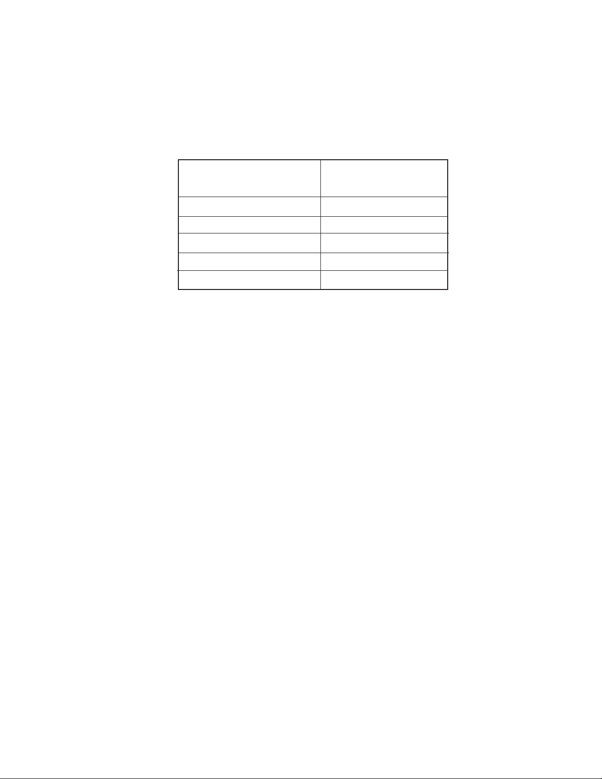
SPECIFICATIONS
AC Power Supply . . . . . . . . . . . . . . . . . . . . . . . . . . . . . .97 to 127 VAC (rated 115VAC), 60 Hz
Amperage . . . . . . . . . . . . . . . . . . . . . . . . . . . . . . . . . . . . . . . . . . . . . . . . . . . . . 6.5 Amps (max)
Minimum Circuit Capacity . . . . . . . . . . . . . . . . . . . . . . . . . . . . . . . . . . . . . . . . . . . . . . .15 Amps
Ice Production per 24 hours (Approximate)
Water Temperature
Ambient Temperature
60⋅F (15⋅C)
70⋅°F (21°C) 46 lbs (21 kg)
80⋅°F (27°C) 47 lbs (21 kg)
90⋅°F (32°C) 40 lbs (18 kg)
100⋅°F (38°C) 40 lbs (18 kg)
110⋅°F (43°C) 38 lbs (17 kg)
Ice Shape . . . . . . . . . . . . . . . . . . . . . . . . . . . . . . . . . . . . . . . . . . . . . . . . . . . 3/4" x 3/4" Square
Ice Thickness @ Normal Setting (Approximate) . . . . . . . . . . . . . . . . . . . . . . . . .0.32" (8.1 mm)
Ice Thickness @ Thin Setting (Approximate) . . . . . . . . . . . . . . . . . . . . . . . . . . .0.28" (7.0 mm)
Ice Thickness @ Thick Setting (Approximate) . . . . . . . . . . . . . . . . . . . . . . . . . . 0.39" (9.9 mm)
15 Inch Storage Capacity (Approximate). . . . . . . . . . . . . . . . . . . . . . . . . . . . . .25 lbs. (11.3 kg)
18 Inch Storage Capacity (Approximate). . . . . . . . . . . . . . . . . . . . . . . . . . . . . .35 lbs. (15.9 kg)
Exterior Dimensions (W x D x H) . . . 15" or 18" x 24" x 34" (381 or 457.2 x 609.6 x 863.6 mm)
Exterior Finish . . . . . . . . . . . . . . . . . . . . . . . . . . . . . . . . . . . . . Stainless Steel or Painted Steel
Net Weight . . . . . . . . . . . . . . . . . . . . . . . . . . 15" = 94 lbs. (42.6 kg) 18" = 123 lbs. (55.8 kg)
Cube Thickness Control . . . . . . . . . . . . . . . . . . . Water Level Sensor & Control Board Setting
Harvest Control . . . . . . . . . . . . . . . . . . . . . . . . . . . . . . . . . . . . . . .Thermistor under Evaporator
Bin Ice Level Control . . . . . . . . . . . . . . . . . . . . . . . . . . . . . . . . . . . . . .Thermistor on side of Bin
Refrigerant . . . . . . . . . . . . . . . . . . . . . . . . . . . . . . . . . . . . . . . . . . . . . . . . . . . . . . . . . . . . R134a
Ambient Temperature . . . . . . . . . . . . . . . . . . . . . . . . . . . . . . . . . . . . . . . . . . . . . . . 55 to 100⋅F
Water Pressure . . . . . . . . . . . . . . . . . . . . . . . . . . . . . . . . . . . . . . . . . . . . . . . . . . 20 to 120 psig
Water Consumption (Dependent On Water Pressure) . . . . . . . . . . 6 to 10 gallons per 4 hours
1-4

INSTALLATION INFORMATION
WARNING
ELECTRICAL SUPPLY REQUIREMENTS
IMPORTANT: If this product is connected to
WARNING
a GFCI (Ground Fault Circuit Interrupter) protected outlet, nuisance tripping of the power
supply may occur, resulting in the loss of cooling. Ice quality may be affected. If nuisance
tripping has occurred, and if the condition of
the ice appears poor, dispose of it.
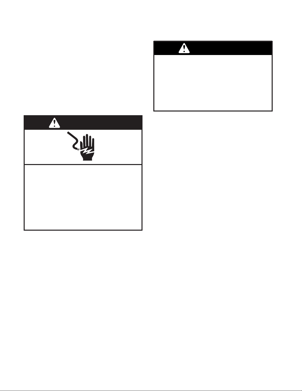
Electrical Shock Hazard
Plug into a grounded 3 prong outlet.
Do not remove ground prong.
Do not use an adapter.
Do not use an extension cord.
Failure to follow these instructions can
result in death, fi re, or electrical shock.
Before you move the ice maker into its fi nal
location, it is important to make sure you have
the proper electrical connection:
• A 115 Volt, 60 Hz, AC only 15- or 20- amp electrical supply , properly grounded in accordance
with the National Electrical Code and local
codes and ordinances, is required.
• It is recommended that a separate circuit,
serving only the ice maker, be provided. Use
a receptacle which cannot be turned off by
a switch or pull chain.
Recommended Grounding Method
For personal safety, this appliance must be
grounded. This appliance is equipped with a
power supply cord having a 3-prong grounding
plug. To minimize possible shock hazard, the
cord must be plugged into a mating, 3- prong,
grounding-type wall receptacle, grounded in
accordance with the National Electrical Code
and local codes and ordinances. If a mating
wall receptacle is not available, it is the personal responsibility of the customer to have
a properly grounded, 3-prong wall receptacle
installed by a qualifi ed electrician.
2-1

WATER SUPPLY AND DRAIN CONNECTIONS
CONNECTING THE WATER LINE
1. Turn off the main water supply.
2. Turn on the nearest faucet and allow it to
run long enough to clear line of water.
3. Find a 1/2"(12.70 mm) to 1-1/4" (3.18
cm) vertical cold water pipe near the ice
maker.
NOTE: A horizontal pipe will work, but drill on
the top side of the pipe, not the bottom. This
will keep water away from the drill motor, and
also keeps normal sediment from collecting in
the valve.
4. Using a grounded drill, a 1/4" (6.35 mm)
hole in the cold water pipe you have selected.
5. Fasten a shutoff valve to the cold water
pipe with a pipe clamp. Make sure that the
outlet end is fi rmly in the 1/4" (6.35 mm)
drilled hole, and that the washer is under
the pipe clamp.
IMPORTANT: Do not use a piercing-type, or
a 3/16" (4.76 mm) saddle-type valve. These
can reduce water fl ow and easily become
clogged.
8. Use 1/4" (6.35 mm) O.D. copper tubing
for the cold water supply and:
a) Measure from the connection at the
back of the ice maker to the cold water
pipe.
b) Add an extra 36" (91.4 cm) to ensure
that you have the proper length. Make
sure both ends of the copper tubing are
cut square.
c) Slip a compression sleeve and com-
pression nut over the ends of the copper
tubing.
d) Insert the end of tubing into the water
shutoff outlet as far as it will go, and
screw the compression nut onto the
outlet. Tighten the compression nut
with an adjustable wrench, but do not
overtighten it.
9. Place the free end of the copper tubing into
a container or sink, and turn on the main
water supply. Flush the tubing until water
is clear, and then turn of f the shutoff valve
on the water pipe. NOTE: Always drain the
water line before making the fi nal connec-
tion to the inlet of the water valve to avoid
a possible water valve malfunction.
6. Tighten the packing nut.
7. Tighten the pipe clamp screws carefully
and evenly so that the washer makes a
watertight seal. Do not overtighten the
pipe clamp. If the water line is soft copper
tubing, you could crush it.
10. Bend the copper tubing to meet the water
line inlet, located on the back of the ice
maker cabinet, as shown below.
2-2

11. Thread the nut onto the coupling at the
end of the copper tubing. Tighten the nut
by hand. Then tighten it with a wrench two
more turns. Do not overtighten.
CONNECTING THE DRAIN
SIDE VIEW
15" Models
Gravity Drain System
Connect the ice maker drain to your drain
in accordance with all state and local codes
and ordinances. If the ice maker is provided
with a gravity drain system, use the following
guidelines when installing the drain lines. This
will avoid water from fl owing back into the ice
maker storage bin and potentially fl owing onto
the fl oor, causing water damage.
• Drain lines must have a minimum of 5/8"
(15.88 mm) inside diameter.
• Drain lines must have a 1" drop per 48"
(2.54 cm drop per 122 cm) of run, or 1/4"
drop per 12" (6.35 mm per 30.48 cm) and
not have any low points where water can
settle.
• The fl oor drains must be large enough to
accommodate drainage from all drains.
• The ideal installation has a standpipe with a
1-1/2" (3.81 cm) to 2" (5.08 cm) PVC drain
reducer installed directly below the outlet of
the drain tube, as shown. Y ou must maintain
a 1" (2.54 cm) air gap between the drain hose
and the standpipe.
18" Models
1. Drain Hose
2. 1" (2.54 cm) Air Gap
3. PVC Drain Reducer
4. Center of drain should be 20" (50.8 cm) back on
15" models from front of door and 23" (58.4cm)
back on 18" models from front of door, with or
without the 3/4" (1.91 cm) panel on the door.
• It may be desirable to insulate the drain line
up to the drain inlet.
2-3
Drain Pump System (On Some Models)
WARNING
WARNING
Connect the ice maker drain to your drain in
accordance with the International Plumbing
Code and any local codes and ordinances.
NOTE: If the drain hose becomes twisted and
water cannot drain, the ice maker will not operate.
Connecting the Drain
After ensuring that the drain system is adequate, follow these steps to properly place
the ice maker:
WARNING
1. Plug in ice maker or reconnect power.
WARNING
Excessive Weight Hazard
Use two or more people to move and
install ice maker.
Failure to do so can result in back or
other injury.
2. Style 1 - For gravity drain system, push
the ice maker into position so that the ice
maker drain tube is positioned over the
PVC drain reducer. Style 2 - For drain
pump system connect the drain pump
outlet hose to the drain. See “Drain Pump
System” earlier in this section.
Electrical Shock Hazard
Plug into a grounded 3 prong outlet.
Do not remove ground prong.
Do not use an adapter.
Do not use an extension cord.
Failure to follow these instructions can
result in death, fi re, or electrical shock.
3. Recheck the ice maker to be sure that it
is level.
4. If it is required by your local sanitation
code, seal the cabinet to the fl oor with
an approved caulking compound after
all water and electrical connections have
been made.
2-4

THEORY OF OPERATION
OPERATING SYSTEMS
There are three operating systems in the ice
maker:
• Refrigeration System
• Water System
• Electrical System
REFRIGERATION SYSTEM
The refrigeration system in the ice maker is
very similar to the system used in other refrigeration appliances. The refrigerant used in this
unit is R134a.
There are two very important additions to the
refrigeration system in the ice maker: the Hot
Gas Valve, and the Condenser Accumulator
Tube. The components operate as follows:
• Hot Gas Valve - Allows high pressure
refrigerant gas to bypass the condenser
and fl ow through the condenser accu-
mulator tube.
• Condenser Accumulator T ube - Hot gas
pushes liquid refrigerant through the
accumulator tube into the evaporator,
helping to evenly heat the evaporator plate so that the ice slab releases
quickly and evenly.
3-1

WATER SYSTEM
The water system provides:
• Fresh water for ice production
• Water recirculation as ice is produced
• Water removal after ice is produced
The water system circulates water to freeze
into ice on the evaporator during the freeze
cycle. During the harvest cycle, it drains away
minerals and contaminates. During the clean
cycle, cleaning solution is circulated to clean
the system of minerals and contaminates.
The hardness of the water supplied to the ice
maker will affect the quality of the ice that is
produced. It may also affect the operation of
the water system.
A water softener , or poly phosphate feeder , will
not cure all of the problems associated with hard
water, but they can be used to reduce scale
buildup in the ice maker. NOTE: Some poly
phosphate feeders will cause a slime buildup
in the water system when the water supply has
a low mineral content.
The ice maker’s water system is shown on
next page.
3-2
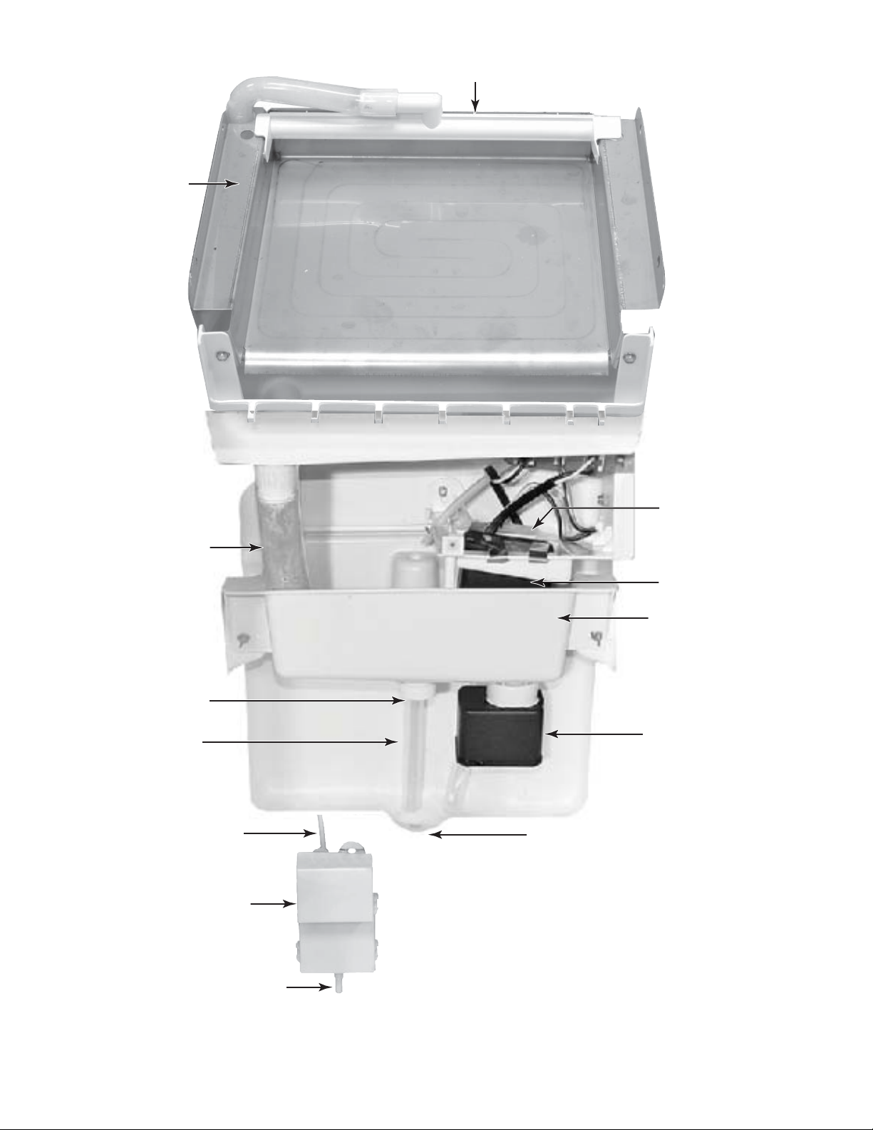
Evaporator
WATER SYSTEM COMPONENT LOCATIONS
Water Distributor
Water Return Tube
Manual Drain
Drain Overfl ow
Water Valve Outlet Tube
Measured Fill
Water Inlet Valve
Water Level Sensor
Water Recirculation
Pump
Reservoir Pan
Reservoir Drain Pump
Bin Drain
From Water Supply
3-3

ELECTRICAL SYSTEM
The ice maker’s electrical system provides power for the refrigeration and water systems, and
controls the operation of each component.
3-4

OPERATIONAL MODES
There are four main operational modes for the
ice maker (more detailed operation is found in
the fl ow chart on page 6-5):
• Freeze
• Harvest
• Clean
• Service (Diagnostics)
ICE MAKING CYCLE
In addition, there are three possible “Off” cycles
for the ice maker. They occur when:
1. The bin is full of ice and the LED is il-
luminated “ON/OFF” (Idle mode).
2. The "On/OFF” control switch has been
held for three seconds. The ON/OFF
LED will go out.
3. The Holiday Mode.
Electrical System
Line Voltage is supplied to the electrical control
switches and the primary side of the step-down
dual transformer. The dual transformer reduces
120 VAC to 8.75 VAC for the cutter grid and
the bin light and 12 V AC for the drain and recirculating pumps. The electronic control board
directs 12 VAC to the water recirculating and
reservoir drain pumps, and 120 VAC to the
hot gas solenoid, condenser fan motor, and
compressor. The measured fi ll water valve will
always have 120 V AC on the BK and WH wires
and 14 VDC on the OR/WH and BK/RD wires.
An evaporator thermistor supplies temperature
information to the electronic control to determine
when to terminate the harvest cycle.
Refrigeration System
The hot gas refrigerant, under high pressure, is
forced through the condenser, where it changes
into a liquid, and fl ows through the drier and
capillary tube into the evaporator. Under low
pressure in the evaporator, the liquid refrigerant
absorbs heat from the water fl owing over the
evaporator as the refrigerant evaporates into
a gas. As a low pressure gas, the refrigerant
fl ows back through the suction line of the heat
exchanger, to the compressor.
During the Freeze mode, some of the hot gas
that is in the condenser accumulating tube,
condenses to a liquid, and remains in the accumulating tube.
During the later stages of the Freeze mode, as
the ice slab forms on the evaporator freezing
plate, some of the refrigerant passing through
the evaporator will not evaporate into a gas, but
will remain a liquid. This liquid refrigerant will
settle in the accumulator, while the refrigerant
vapor is sucked off through the suction tube at
the top of the accumulator. This accumulated
liquid refrigerant will eventually be directed to
the evaporator to quickly warm the evaporator
plate during the Harvest mode.
NOTE: It is very important that the accumulator
is not tilted out of a horizontal position. If moved,
it could cause compressor failure.
Water System
The water recirculating pump moves the water
from the reservoir pan up to the distributor,
where it fl ows out over the evaporator freez-
ing plate.
Water that does not freeze on the evaporator
plate runs off the front edge, and falls back into
the reservoir, where it is recirculated back to
the water distributor.
As the ice slab forms, the minerals in the water
are on the surface of the ice. The water fl ow-
ing over the top of the ice slab washes these
minerals back into the water reservoir pan. The
water continues to recirculate until the water
level in the reservoir drops to the bottom of the
water level sensor. When the water level in the
reservoir drops below the sensor, the control
terminates the freeze mode and initiates the
harvest mode.
The control signals the measured fi ll valve to fi ll
to the selected water level setting. The measured fi ll valve uses a fl ow meter to accurately fi ll
to the correct volume. Thin Ice uses 32 ounces
(954cc), Normal Ice 37 ounces (1106cc), and
Thick Ice 42.5 ounces (1258cc).
3-5

HARVEST MODE
Electrical System
When the water level in the reservoir drops
below the water level sensor it signals the
electronic control to terminate power to the
condenser fan, and then the water recirculating
pump. The reservoir drain pump is activated
to fully drain the reservoir. Power is then supplied to the hot gas valve and a fi ll request is
sent to the measured fi ll valve. The fi ll valve
fi lls to the requested volume while the hot gas
valve is energized for the balance of the harvest mode.
If the evaporator thermistor is unplugged, the
evaporator defaults to a timed 4 minute harvest.
If the water level sensor is disconnected or
open, the control defaults to 25 minutes of
freeze time. The cleaning indicator LED feature will not function if the water level sensor
is disconnected.
Refrigeration System
The hot gas valve opens, allowing high pressure refrigerant gas to bypass the condenser,
and fl ow through the condenser accumulating
tube. The hot gas pushes the liquid refrigerant
that has accumulated in the accumulator tube
up into the evaporator. The hot liquid refrigerant
evenly heats the evaporator plate so that the
ice slab releases quickly and evenly.
The ice slab, when released, slides off of the
evaporator plate onto the cutter grid.
Water System
The electronic control board sends a signal to
the water valve. The signal tells the water valve
how much water to be fi lled, allowing water to
fl ow into the water reservoir pan. The water
fi ll volume is determined by the ice thickness
setting.
As a result of the hot gas fl ow and the ice sliding
off the evaporator plate, the evaporator temperature begins to rise. When the evaporator
thermistor reaches the set temperature (52°F),
the unit switches to the Freeze mode. This cycling between Freeze and Harvest, continues
until the ice bin is full.
The electronic control board operates the various components and systems in the ice maker
for each of the Freeze and Harvest modes.
CLEAN MODE
Electrical System
The electronic control board operates the
various components and systems during the
Clean mode.
For the order of the components cycled, see
the fl ow chart on page 6-13.
Water System
When the service control switch is in the “Clean”
position, the water recirculating pump circulates
the cleaning solution that has been added to the
reservoir, up to the water distributor , across the
evaporator, and back into the reservoir, where
it is recirculated. The compressor and hot gas
valve operate to heat the evaporator.
DIAGNOSTIC MODE
1. Do not continue with the diagnosis of the ice
maker if a fuse is blown, a circuit breaker
is tripped, or if there is less than a 120 volt
power supply at the wall outlet.
2. All units that have failed during the fi rst few
days of use should be checked for loose
connections or miswiring.
Entering and Navigating — Manual
Diagnostics
• Turn the product on. Within 10 seconds of
Power On, press and hold the On and the
Clean buttons. Release both buttons when
all user interface LEDs begin to fl ash.
• Within 5 seconds of all LEDs fl ashing, push
any other button on the user interface. This
begins manual diagnostics.
• If no button is pressed within 5 seconds, the
product goes into the automatic diagnostic
mode used at the assembly plant. Each
component is cycled for 5 seconds.
• The Service button (or Off button on some
models) is used to advance through each
step.
• T o exit manual diagnostics, press the Power
button (or On button on some models)
3-6
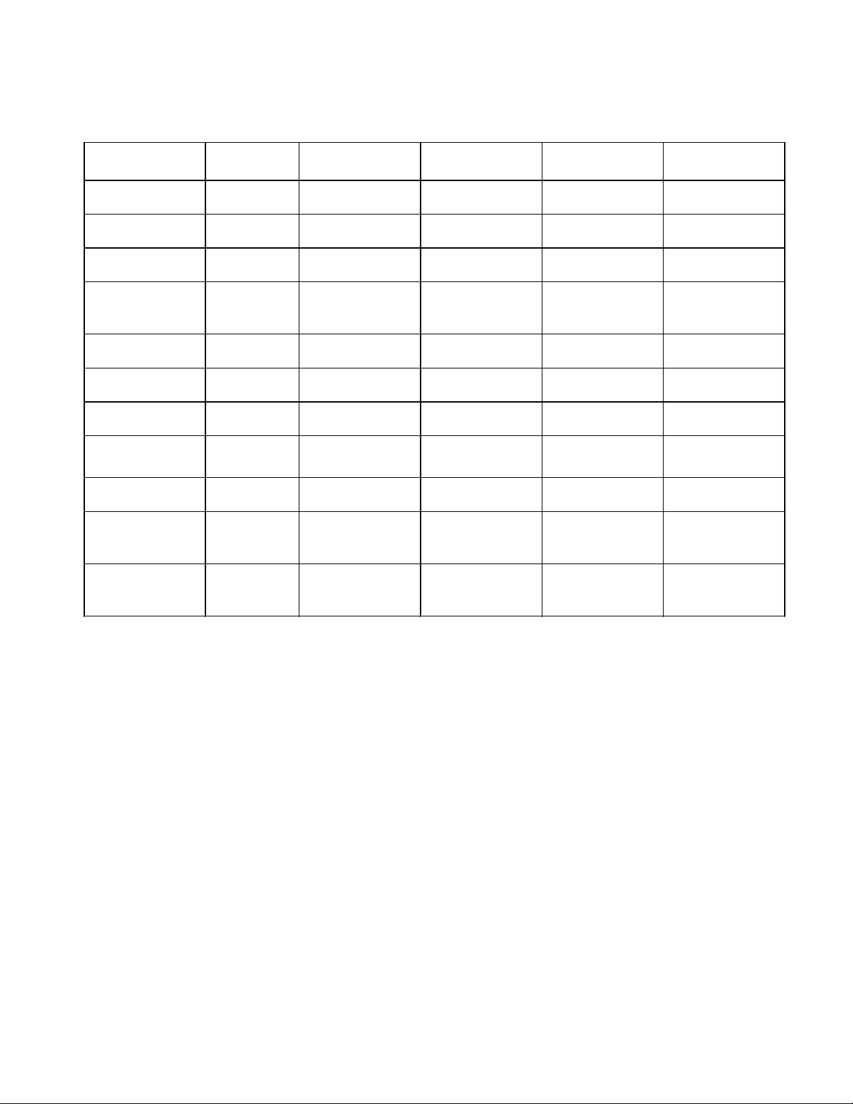
Diagnostic Chart
After pressing any button to enter manual diagnostics all LEDs will illuminate for 5 seconds. The
controls will then automatically move to the fi rst component.
Order Component On/Off LED
1 Entry intoTest
2 Bin Thermistor ON Solid--OK
3 Evaporator
4a Water Valve
4b Water Level
5 Recirculation
6 Reservoir Drain
7 Compressor and
8 Compressor and
9 Twice Ice OFF OFF ON Solid--No delay
10 Ice Thickness OFF 2 Blinks--Thin
Mode
Thermistor
4 min time out
Service button
press will advance
to step 6
Sensor
Pump
Pump
Condenser Fan
Motor
Hot Gas Valve
(On for some
models)
ON ON ON ON
2 blinks--Open
4blinks--Short
OFF OFF ON Solid--OK
OFF ON Solid--reservoir full
OFF ON Solid--reservoir full
ON ON ON OFF
ON OFF OFF OFF
ON Solid while cooling Blinking when evap
ON Solid while heating ON Solid while heating
Service LED
(Off for some
models)
OFF OFF OFF
Blinking--reservoir
empty
Blinking--reservoir
empty
thermistor reaches
4.5ºF; full frost pattern
should be visible
Blinking when evap
thermistor reaches 52ºF
4 Blinks--Normal
6 Blinks--Thick
Press Clean button to
cyclebetween settings
Clean LED Feature Light (for
2blinks--Open
4blinks--Short
ON OFF
ON OFF
ON OFF
ON Solid while heating OFF
Blinking--10 min delay
between cycles
Press Clean button to
cyclebetween settings
OFF OFF
some models)
OFF
OFF
ERROR DISPLAYS
These errors will occur at any time during normal operation if a thermistor fails.
2 Blinks — Service Light is blinking twice in repeating intervals – This signifi es a bin thermistor
failure. Check that the bin thermistor is plugged in to the control box. Check that the bin thermistor is not open or shorted. Replace the thermistor if it is open or shorted.
3 Blinks — Service Light is blinking three times in repeating intervals – This signifi es a harvest
failure. Check that the evaporator thermistor is connected to the sealed system tubing. If the
thermistor is plugged in, ensure that it is fully connected to the control box. (The ice maker will
operate on a timed cycle if the evaporator thermistor is unplugged.) Check the resistance of the
thermistor. If the thermistor checks good, then look for a frost pattern on the evaporator plate.
The unit may be low on refrigerant.
HOLIDAY MODE
The Holiday Mode feature is designed for the traveler or for those whose religious observances
require turning off the lights and the ice maker. By selecting this feature, ice production and the
interior lights will be disabled. Press and hold the Holiday Mode button to turn on the Holiday
Mode feature. Press and hold the button again to turn off the feature.
The Holiday mode LED is lite constantly in this mode.
3-7
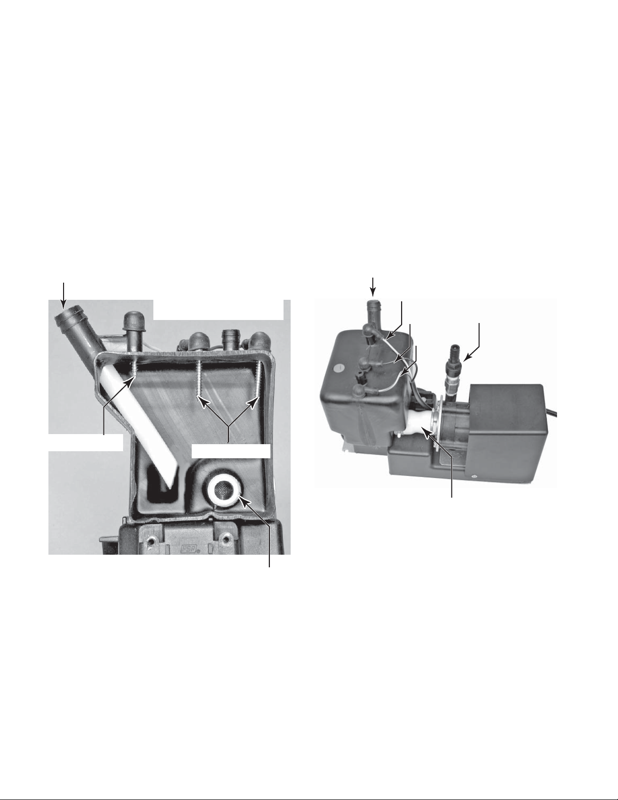
MODELS WITH INTERNAL DRAIN PUMPS
The power cord on the internal drain pump is
connected to a 120 VAC wall outlet. The ice
maker is then connected to the 120 V AC outlet
on the drain pump. If the drain pump fails, or if
the drain becomes blocked, power is shut off
to the 120 VAC outlet on the drain pump.
When the unit is fi rst plugged in, the drain
pump will run for 20 seconds. The power can
be disconnected and reconnected to verify that
the pump is operating properly.
Water from the ice maker reservoir, or melting
ice from the bin, drains down the bin drain tube
Pump Inlet
Contacts Sense Continuity
Through The Water
into the pump inlet, and then into the drain pump
chamber. As the water level rises, it bridges the
“full” contacts, and the pump starts to run. The
pump discharges the water through the outlet
and the check valve. When the “full” connection
is removed, the pump runs for an additional 12
seconds to empty the tank.
If the water level in the drain pump continues
to rise, due to a slow or blocked drain, or a
blocked vent hose, and touches the “overfi ll”
contact, power will be turned off to the drain
pump’s 120 V AC outlet, causing the ice maker
to turn off.
Vent Outlet
White
Black
Green
Pump Outlet &
Check Valve
Overfi ll Contact
Full Contacts
Connector Hose
(Contains Screen Washer)
Screen
Washer
3-8

COMPONENT ACCESS
This section instructs you on how to service each component inside the 2007 Design 15” & 18”
Automatic Ice Makers. The components and their locations are shown below.
COMPONENT LOCATIONS
Evaporator
NOTE: The Evaporator
Thermistor Is Located On
Tubing Below Evaporator
Cutter Grid
Compressor
Condenser
Fan Motor
Dual Transformer
Light Switch
Electronic Control Board
Push-button
Switch
Bin
Thermistor
Water Level
Sensor
Water
Recirculation
Pump
Reservoir
Drain Pump
Hot Gas Valve &
S o l e n oi d ( B e hi n d
Condenser)
Measured Fill
Water Valve
Condenser
Condenser Accumulator Tube
4-1
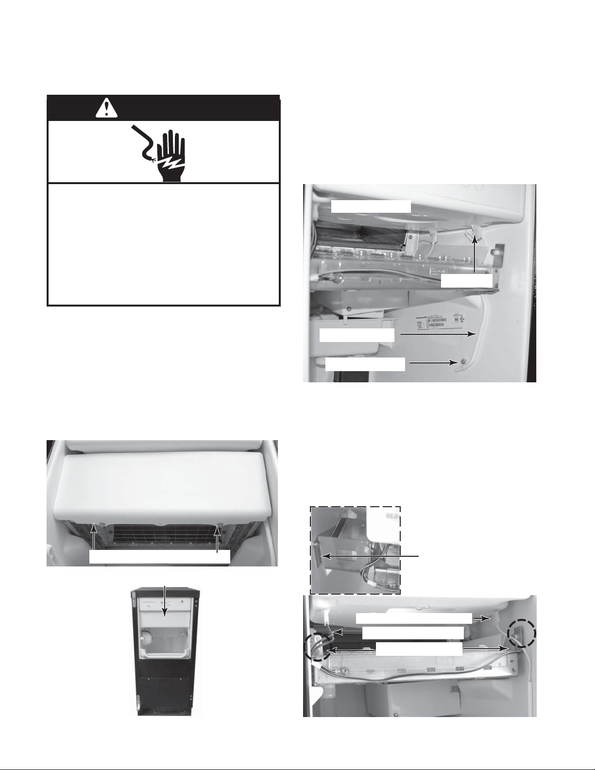
REMOVING THE BIN THERMISTOR, CUTTER GRID,
WARNING
EVAPORATOR THERMISTOR, & WATER DISTRIBUTOR
WARNING
Electrical Shock Hazard
Plug into a grounded 3 prong outlet.
Do not remove ground prong.
Do not use an adapter.
Do not use an extension cord.
Failure to follow these instructions can
result in death, fi re, or electrical shock.
1. Unplug ice maker or disconnect power.
2. Open the ice maker door.
3. Cover or remove the ice from the storage
bin.
4. Place a cloth in the drain hole to avoid
hardware from falling inside.
5. Remove the two hex-head screws from the
cutter grid cover and remove the cover.
Cutter Grid Cover
6. To remove the bin thermistor:
a) Disconnect the bin thermistor connector
from the bottom of the control housing.
b) Pull the bin thermistor out of the retain-
ing clamp and remove it.
Control Housing
Connector
Bin Thermistor
Retaining Clamp
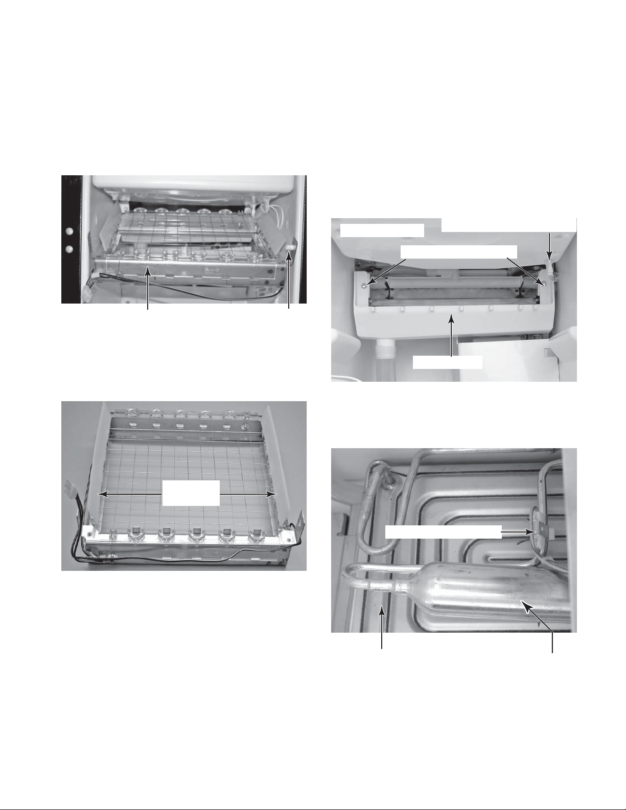
7. To remove the cutter grid:
a) Disconnect the cutter grid and bin
thermistor connectors from the bottom
of the control housing.
b) Remove the two hex-head screws from
both sides of the cutter grid. The longer
screw and white spacer are on the right
side.
Cutter Grid Cover Screws
Cutter Grid Cover
4-2
Spacer Bracket (Left Side)
˝ Models
18
Bin Thermistor Connector
Cutter Grid Connector
Cutter Grid Screws
c) Slide the cutter grid forward and out of
the unit and place it on a work surface.
Be careful not to scratch the ice maker
liner.
d) Remove the spacer from the right cutter
grid bracket tab.
8. To remove the evaporator thermistor:
a) Remove the cutter grid from the unit
(see step 7 on page 4-2 for the procedure).
b) Disconnect the evaporator thermistor
connector from the bottom of the control
housing.
c) Remove the two hex-head mounting
screws from the water trough and pull
the trough from the unit.
Cutter Grid
Spacer
e) Unsnap the two ice guides from the
cutter grid tabs. There should be a
slight outward tilt after the guides are
installed. Bend the metal tabs outward
if necessary.
Cutter Grid
Ice Guides
Control Housing
Water T rough Screws
Evap Thermistor Connector
Water T rough
d) Reach behind the accumulator, and
unclip the evaporator thermistor from
the evaporator tubing and remove it.
Evaporator Thermistor
Bottom Of The Evaporator
4-3
Accumulator
Continued on the next page.
 Loading...