

Whirlpool KDDS 6010, KDDS 6010 KA INSTALLATION

KDDS 6010 - KDDD 6010
Assembly instructions
5019_102_00273_INSTAL_GB 30-05-2007 13:25 Pagina 1

5019_102_00273_INSTAL_GB 30-05-2007 13:25 Pagina 2

Note to the installer 4
Note to the customer 4
Parts supplied - double & single models 5
Tools needed 5
Installation preparation - double & signle models 6
Electrical information - double & single models 7
Service specifications - double models 8
The cavity - double models 9
Plumbing options - double models 10
Service specifications - single models 11
The cavity - single models 12
Plumbing options - single models 13
Installation instructions 14
Step 1: moving the product into the cavity 14
Step 2: removing the tub 15
Step 3: adjusting the feet (double models only) 16
Step 4: securing the product 17
Step 5: refitting the tub 17
Step 6: connecting the drain hoses 18
Step 7: connecting the inlet hose and power supply 19
Step 8: measuring the toe kick 19
Step 9: trimming the toe kick (double models only)) 20
Step 10: fitting the toe kick to the product
(double models only) 20
Step 11: Final checklist (double and single models) 21
Step 12: customer support 21
5019_102_00273_INSTAL_GB 30-05-2007 13:25 Pagina 3

1. Read these instructions completely and carefully.
2. Installation of this requires basic mechanical and electrical skills.
3. Be sure to leave these Instructions with the Customer.
4. At the completion of the installation, the Installer must perform Final Check List as per
Section 11 of these Installation Instructions.
5. Remove all packaging materials supplied with the .
Note to the installer
4
Keep these Installation Instructions with your User Guide for future reference. must be securely
anchored before it is operated.
WARNING!
Before installing the , remove the house fuse or open the circuit breaker. Ensure all
water connections are turned OFF. It is the responsibility of the plumber and electrician to ensure that each installation complies with all Codes and Regulations.
Important!
These instructions must be followed precisely to ensure correct venting and operation of the
. In the event of a fault related to the incorrect installation, the installer will be liable
for any repairs.
Important!
The MUST be installed to allow for future removal from the enclosure if service is required.
Important!
Improper installation is not covered under the Warranty.
Important!
If the is to be relocated from one installation to another it must be kept upright to
avoid damage from water spillage.
Note to the customer
5019_102_00273_INSTAL_GB 30-05-2007 13:25 Pagina 4
R
R
R
R
R
R
R
R
Parts supplied - double & single models
Wooden Chopping Board
Tape Measure
Spirit Level
Safety Glasses
Utility Knife
Pencil Side
Sandpaper
Drill & No.2 Phillips Bit
Phillips Screwdriver
Flat Screwdriver
Adjustable Wrench or M5 Socket
Ø50mm Hole Saw
Cutting Pliers
Tools needed
5
5019_102_00273_INSTAL_GB 30-05-2007 13:25 Pagina 5
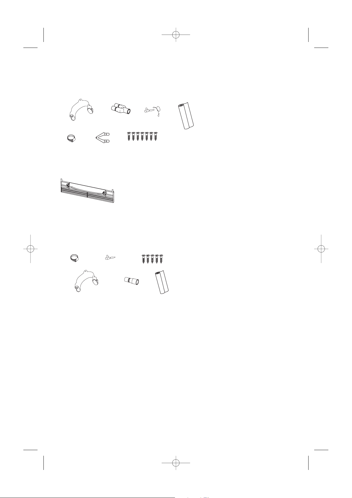
DOUBLE MODELS
INSTALLATION KIT
Drain Hose
Support (1)
Clamp (1)
Installation
Tabs (2)
Drain Hose
Joiner (1)
Prefinished
Toe Kick (1)
White prefinished toe kick kit
or Black prefinished toe kick kit
or Iridium prefinished toe kick kit
Wire
Clips (2)
Phillips 16mm
Screws (7)
Moisture
Protection
Tape (1)
SINGLE MODELS
INSTALLATION KIT
Clamp (1)
Drain Hose
Support (1)
Wire
Clip (1)
Drain Hose
Joiner (1)
Phillips 16mm
Screws (5)
Moisture
Protection
Tape (1)
ELECTRICAL PREPARATION
A) The switched power outlet for the appliance should be installed in a cabinet or on a wall adjacent to the
under bench space in which the appliance is to be installed. Note: The power outlet must be accessible
after installation.
B) The power outlet should be positioned between 150mm and 450mm from the cavity.
PLUMBING & DRAINAGE PREPARATION
A) A readily accessible valve must be installed in the water supply pipe.
B) If the supply pressure exceeds 1000kPa, then a pressure limiting valve must be used.
C) Review Plumbing Options on pages 4 or 6. Choose a method that best suits your needs.
D) A Drain Hose extension Kit P/N 525798 will extend the drain hose(s) by 3.6m. The kit is available from
the nearest Fisher & Paykel Authorised Service Agent. DO NOT extend beyond this limit.
E) This Dishwasher’s maximum drain height is 950mm.
CAVITY PREPARATION
A) It is required that all cabinetry surrounding the (including underside of the benchtop) is
sealed with an oil based paint or moisture-proof polyurethane to prevent possible steam damage. The
air in the cavity can get very hot and humid (saturated at 50oC)
B) The self-adhesive moisture protection tape must be applied to the underside of the benchtop to
prevent moisture damage, (refer to cavity diagram pg 3 or 5). Ensure surfaces are dry and dust-free
prior to application.
C) Ensure the cavity provides sufficient material to secure the using the mounting tabs (refer to
step 1, page 7). If there is nothing to screw to, add a brace. See page 3 or 5 for screw locations.
D) The services hole MUST be immediately adjacent to the rear lower corner of the cabinetry. If not, the
hoses will prevent the being pushed back into the cavity all the way. The hole can be located
on either side depending on the location of the services.
E) Ensure the cavity sides are plumb (vertical) as this will assist with
levelling the .
F) Minimum clearances:
Installation preparation - double & signle models
6
5019_102_00273_INSTAL_GB 30-05-2007 13:25 Pagina 6
R
R
R
R
2.5mm
2.5mm
R
13mm

POWER SUPPLY CORD
A) Care should be taken when the appliance is installed or removed, to reduce the likelihood of damage to
the power supply cord.
B) If the power supply cord is damaged, it must be replaced by the Manufacturer, Service Agent or a
similarly qualified person, in order to avoid a hazard.
EARTHING INSTRUCTIONS
A) This appliance must be earthed. In the event of malfunction or breakdown, earthing will reduce the risk
of electric shock by providing a path of least resistance for electric current.
WARNING!
Improper connection of the equipment-earthing conductor can result in a risk of electric shock.
Check with a qualified electrician or service representative if you are in doubt as to whether
the appliance is properly earthed.
B) This appliance is equipped with a power supply cord having an equipment-earthing conductor and an
earthing plug. The power supply plug must be plugged into an appropriate outlet that is installed and
earthed in accordance with all local Codes and Regulations.
WARNING!
Do not modify the power supply plug provided with the appliance - it will not fit the outlet,
have a proper outlet installed by a qualified electrician. Do not use an extension cord, adaptor
plug or multiple outlet box.
Electrical information - double & single models
7
5019_102_00273_INSTAL_GB 30-05-2007 13:25 Pagina 7
WATER CONNECTION
Recommended COLD (Maximum 60°C).
3/4 “ BSP (GB20) to suit flat washer.
WATER SOFTENER MODELS
Refer to your User Guide on how to set up your water softener.
WATER PRESSURE
Maximum Minimum
Water Softener Models 1000kPa (145 p.s.i.) 100kPa (14,5 p.s.i.)
Other Models 1000kPa (145 p.s.i.) 30kPa (4,3 p.s.i.)
DRAIN CONNECTION
Drain Hose Joiner to suit Ø19mm ± 2mm waste tee.
ELECTRICAL CONNECTION
220-240 VAC power outlet, 9 Amps Minimum.
LENGTH OF SERVICES (FROM PRODUCT EXIT POINT)
Drain hose - 2250mm
Inlet hose - 1750mm
Power supply cord - 1965mm
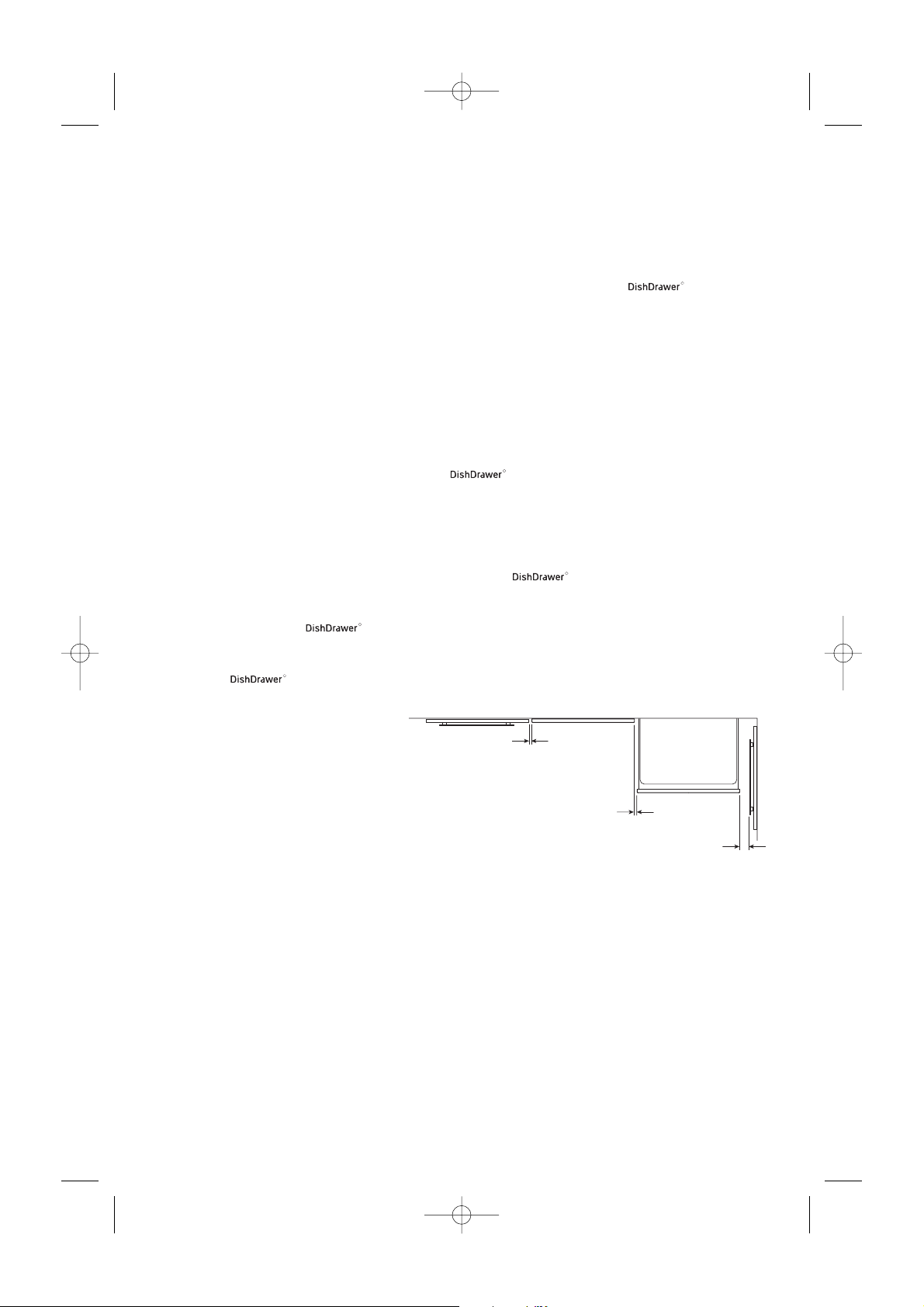
NOTE: Services approximately exit product 189mm from left; 550mm from front; 793mm from top.
Prefinished model shown
* For an Integrated the product depth is specified with an 18mm Integrated Panel thickness.
** Depth of product excludes Curvature (30mm), or Handle.
† TOE KICK DEPTH
67mm less the Toe Kick Panel thickness (Minimum Panel thickness using the supplied screws is 9mm).
# DOOR FRONT HEIGHT
719.5mm minimum.
Service specifications - double models
8
5019_102_00273_INSTAL_GB 30-05-2007 13:25 Pagina 8
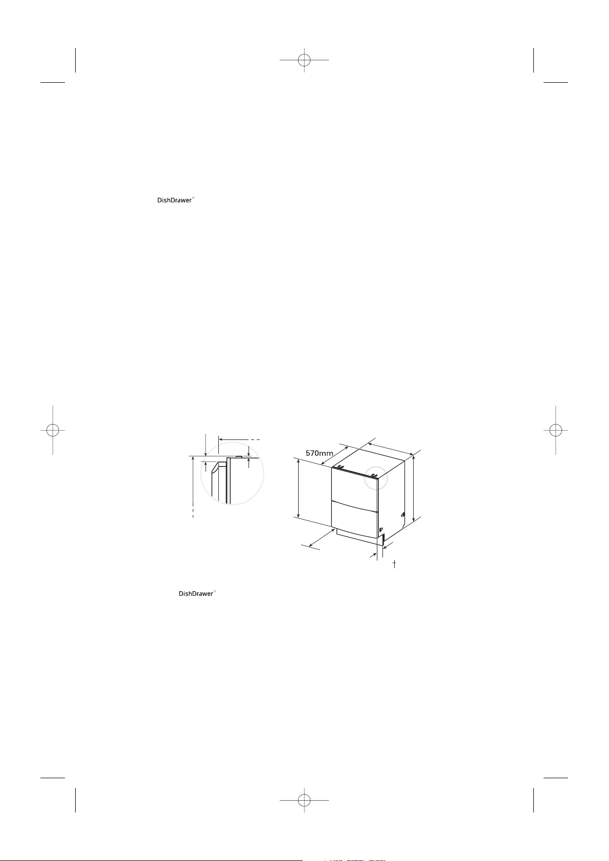
R
8mm
570mm
2mm
Tabs
*
595mm
#
Side View
819.5 - 879.5 mm
719.5mm
520mm
Drawer Open
67mm
R
819.5 - 879.5mm
 Loading...