

Whirlpool GZ9730SSS0, GZ9730XSS0, GZ9736SSS0, GZ9736XSS0 Owner’s Manual
30"(76.2CM) AND 36" (91.4 CM)
WALL-MOUNTCANOPY RANGEHOOD
HOTTEDE CUISINI_: POUR MONTAGE MURAL
30" (76,2 CM) 36" (91,4 CM)
Table of Contents/Table des matieres ............................................................................. 2
IMPORTANT: READ AND SAVE THESE INSTRUCTIONS. FOR RESIDENTIAL USE ONLY.
iMPORTANT : LIRE ET CONSERVER CES INSTRUCT_ONS. POUR UT_USATION RC:SIDENTIELLE UNIQUEMENT.
W10029770A
TABLEOF CONTENTS
TABLEDESMATIERES
RANGE HOOD SAFETY ................................................................. 2
INSTALLATION REQUIREMENTS ................................................ 4
Tools and Parts ............................................................................ 4
Location Requirements ................................................................ 4
Venting Requirements (vented models only) ............................... 5
Electrical Requirements ............................................................... 6
INSTALLATION INSTRUCTIONS .................................................. 7
Prepare Location .......................................................................... 7
Install Mounting Bracket .............................................................. 7
Install Flue Mounting Bracket ...................................................... 8
Prepare Range Hood ................................................................... 8
Install Range Hood ....................................................................... 9
Complete Installation ................................................................. 12
RANGE HOOD USE ...................................................................... 12
Range Hood Controls ................................................................ 12
RANGE HOOD CARE ................................................................... 12
Cleaning ...................................................................................... 12
WIRING DIAGRAM ...................................................................... 14
ASSISTANCE OR SERVICE ......................................................... 15
In the U.S.A ................................................................................ 15
Accessories ................................................................................ 15
In Canada ................................................................................... 15
WAR RANTY .................................................................................. 16
SI_CURITI_ DE LA HOTTE DE CUISINII_RE ............................... 17
EXIGENCES D'INSTALLATION ................................................... 19
Outillage et pieces ...................................................................... 19
Exigences d'emplacement ......................................................... 19
Exigences concernant I'evacuation
(seulement pour modeles avec decharge a I'exterieur) ............. 20
Specifications electriques .......................................................... 21
INSTRUCTIONS D'INSTALLATION ............................................. 22
Preparation de I'emplacement ................................................... 22
Installation de la bride de montage ............................................ 22
Installation de la bride de montage du cache-conduit .............. 23
Preparation de la hotte de cuisiniere ......................................... 23
Installation de la hotte de cuisiniere ........................................... 24
Achever I'installation .................................................................. 27
UTILISATION DE LA HOTTE DE CUISINII_RE ........................... 28
Commandes de la hotte de cuisiniere ....................................... 28
ENTRETIEN DE LA HOTTE DE CUISINII_RE ............................. 28
Nettoyage ................................................................................... 28
SCHI_MA DE CABLAGE ............................................................... 30
ASSISTANCE OU SERVICE ......................................................... 31
Liste d'accessoires ..................................................................... 31
Au Canada .................................................................................. 31
GARANTIE ..................................................................................... 32
RANGE HOOD SAFETY
Your safety and the safety of others are very important.
We have provided many important safety messages in this manual and on your appliance. Always read and obey all safety
messages.
This is the safety alert symbol.
This symbol alerts you to potential hazards that can kill or hurt you and others.
All safety messages will follow the safety alert symbol and either the word "DANGER" or "WARNING."
These words mean:
You can be killed or seriously injured if you don't immediately
follow instructions.
You can be killed or seriously injured if you don't follow
instructions.
All safety messages will tell you what the potential hazard is, tell you how to reduce the chance of injury, and tell you what can
happen if the instructions are not followed.
iMPORTANT SAFETY iNSTRUCTiONS
WARNING: TO REDUCE THE RISK OF FIRE, ELECTRIC
SHOCK, OR INJURY TO PERSONS, OBSERVE THE
FOLLOWING:
[] Use this unit only in the manner intended by the
manufacturer. If you have questions, contact the
manufacturer.
[] Before servicing or cleaning the unit, switch power off at
service panel and lock the service disconnecting means to
prevent power from being switched on accidentally. When
the service disconnecting means cannot be locked,
securely fasten a prominent warning device, such as a tag,
to the service panel.
[] Installation work and electrical wiring must be done by
qualified person(s) in accordance with all applicable codes
and standards, including fire-rated construction.
[] Sufficient air is needed for proper combustion and
exhausting of gases through the flue (chimney) of fuel
burning equipment to prevent backdrafting. Follow the
heating equipment manufacturer's guideline and safety
standards such as those published by the National Fire
Protection Association (NFPA), the American Society for
Heating, Refrigeration and Air Conditioning Engineers
(ASHRAE), and the local code authorities.
[] When cutting or drilling into wall or ceiling; do not damage
electrical wiring and other utilities.
[] Ducted fans must always be vented outdoors.
CAUTION: For general ventilating use only. Do not use
to exhaust hazardous or explosive materials and vapors.
CAUTION: To reduce risk of fire and to properly exhaust
air, be sure to duct air outside - do not vent exhaust air into
spaces within walls or ceilings, attics or into crawl spaces,
or garages.
WARNING: TO REDUCE THE RISK OF FIRE, USE ONLY
METAL DUCTWORK.
WARNING: TO REDUCE THE RISK OF A RANGE TOP
GREASE FIRE:
[] Never leave surface units unattended at high settings.
Boilovers cause smoking and greasy spillovers that may
ignite. Heat oils slowly on low or medium settings.
[] Always turn hood ON when cooking at high heat or when
flambeing food (i.e. Crepes Suzette, Cherries Jubilee,
Peppercorn Beef Flambe).
[] Clean ventilating fans frequently. Grease should not be
allowed to accumulate on fan or filter.
[] Use proper pan size. Always use cookware appropriate for
the size of the surface element.
WARNING: TO REDUCE THE RiSK OF iNJURY TO
PERSONS iN THE EVENT OF A RANGE TOP GREASE
FIRE, OBSERVE THE FOLLOWING: _
[] SMOTHER FLAMES with a close fitting lid, cookie sheet, or
metal tray, then turn off the burner. BE CAREFUL TO
PREVENT BURNS. If the flames do not go out
immediately, EVACUATE AND CALL THE FIRE
DEPARTMENT.
[] NEVER PICK UP A FLAMING PAN - you may be burned.
[] DO NOT USE WATER, including wet dishcloths or towels -
a violent steam explosion will result.
[] Use an extinguisher ONLY if:
- You know you have a class ABC extinguisher, and you
already know how to operate it.
- The fire is small and contained in the area where it
started.
- The fire department is being called.
- You can fight the fire with your back to an exit.
aBased on "Kitchen Fire Safety Tips" published by NFPA.
[] WARNING: To reduce the risk of fire or electrical shock,
do not use this fan with any solid-state speed control
device.
SAVE THESE INSTRUCTIONS
INSTALLATIONREQUIREMENTS
Gather the required tools and parts before starting installation.
Read and follow the instructions provided with any tools listed
here.
Tools needed
• Level
• Drill
• %6" (8 mm) drill bits for pilot holes
• %2" (4 mm) drill bits
• Pencil
• Tape measure or ruler
• Caulking gun and weatherproof caulking compound
• Phillips screwdriver
• Vent clamps
• Metal snips
For vented installations, you will also need:
• 1wall or roof cap
• Metal vent system
For non-vented (recirculation} installations, you will also
need:
• Charcoal Filter Kit Part Number 8212566
See "Assistance or Service" section to order.
• 5" (12.7 cm) diameter expandable/flexible aluminum duct
• Vent clamps for a 6" (15.2 cm) diameter duct
Parts supplied
Remove parts from packages. Check that all parts are included.
• Literature package
• Decorative flue assembly
• 2 metal grease filters for 30" (76.2 cm) models
3 metal grease filters for 36" (91.4 cm) models
• Parts bag containing:
• Damper
• Mounting bracket
• Flue mounting bracket
• 8 drywall anchors
• 8 - 4.8 x 38 mm pan head mounting screws
• 6- 3.9 x 9.5 mm pan head screws
• 2 - 3.9 x 5.7 mm flat head screws
IMPORTANT: Observe all governing codes and ordinances.
It is the installer's responsibility to comply with installation
clearances specified on the model/serial rating plate. The model/
serial rating plate is located behind the left filter on the rear wall of
the vent hood.
Canopy hood location should be away from strong draft areas,
such as windows, doors and strong heating vents.
Cabinet opening dimensions that are shown must be used. Given
dimensions provide minimum clearance. Consult the cooktop/
range manufacturer installation instructions before making any
cutouts.
Grounded electrical outlet is required. See "Electrical
Requirements" section.
The canopy hood is factory set for venting through the roof or
wall. For non-vented (recirculating) Installation see "Non-vented
(recirculating) Installations" in "Prepare Location" section.
Charcoal Filter Kit Part Number 4393848 is available from your
dealer or an authorized parts distributor.
All openings in ceiling and wall where canopy hood will be
installed must be sealed.
For Mobile Home Installations
The installation of this range hood must conform to the
Manufactured Home Construction Safety Standards, Title 24
CFR, Part 328 (formerly the Federal Standard for Mobile Home
Construction and Safety, Title 24, HUD, Part 280) or when such
standard is not applicable, the standard for Manufactured Home
Installation 1982 (Manufactured Home Sites, Communities and
Setups) ANSI A225.1/NFPA 501A*, or latest edition, or with local
codes.
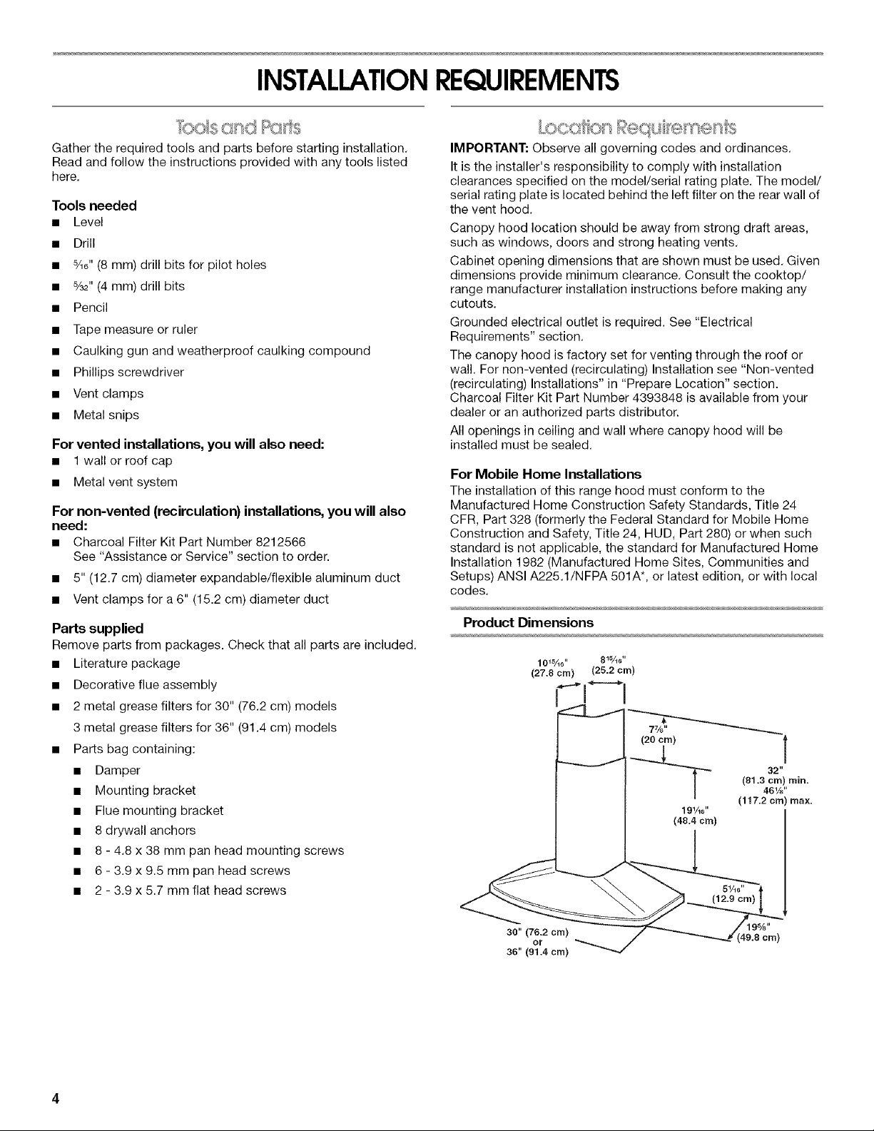
Product Dimensions
101%6,, 81¾_"
(27.8 cm) (25.2 cm)
30" (76.2 cm)
or
36" (91.4 cm)
(49.8 cm)
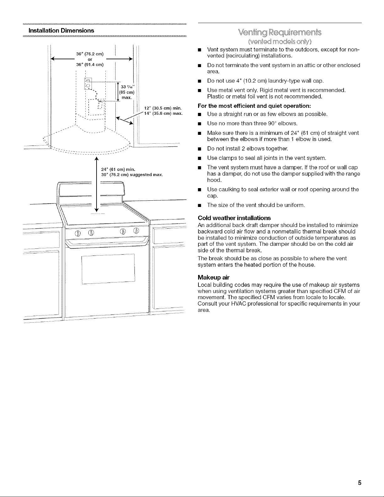
Installation Dimensions
30" (76.2 cm)
or
35" (91.4 cm)
1
12" (30.5 cm) min.
24" (61 cm) rain.
30" (76.2 cm) suggested max.
...... J
........................ /
max.
• Vent system must terminate to the outdoors, except for non-
vented (recirculating)installations.
• Do not terminate the vent system in an attic or other enclosed
area.
• Do not use 4" (10.2 cm) laundry-type wall cap.
• Use metal vent only. Rigid metal vent is recommended.
Plastic or metal foil vent is not recommended.
For the most efficient and quiet operation:
• Use a straight run or as few elbows as possible.
• Use no more than three 90° elbows.
• Make sure there is a minimum of 24" (61 cm) of straight vent
between the elbows if more than 1 elbow is used.
• Do not install 2 elbows together.
• Use clamps to seal all joints in the vent system.
• The vent system must have a damper. If the roof or wall cap
has a damper, do not use the damper supplied with the range
hood.
• Use caulking to seal exterior wall or roof opening around the
cap.
• The size of the vent should be uniform.
Cold weather installations
An additional back draft damper should be installed to minimize
backward cold air flow and a nonmetallic thermal break should
be installed to minimize conduction of outside temperatures as
part of the vent system. The damper should be on the cold air
side of the thermal break.
The break should be as close as possible to where the vent
system enters the heated portion of the house.
Makeup air
Local building codes may require the use of makeup air systems
when using ventilation systems greater than specified CFM of air
movement. The specified CFM varies from locale to locale.
Consult your HVAC professional for specific requirements in your
area.
Venting Methods
This canopy hood is factory set for venting through the roof or
wall.
A 6" (15.2 cm) round vent system is needed for installation (not
included). The hood exhaust opening is 6" (15.2 cm) round.
NOTE: Flexible vent is not recommended. Flexible vent creates
back pressure and air turbulence that greatly reduce
performance.
Vent system can terminate either through the roof or wall. To vent
through a wall, a 90° elbow is needed.
Rear discharge
A 90°elbow may be installed immediately above the hood.
For non-vented (recirculating) installations
If it is not possible to vent cooking fumes and vapors to the
outside, the hood can be used in the non-vented (recirculating)
version, fitting an activated carbon filter and the deflector. Fumes
and vapors are recycled through the top grille.
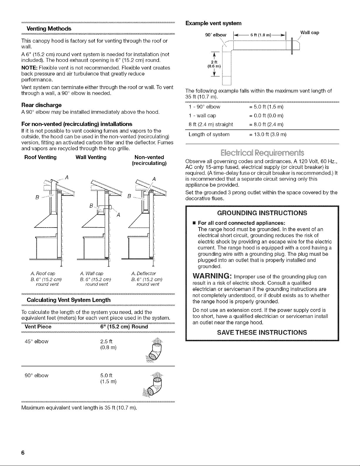
Roof Venting WallVenting Non-vented
(recirculating)
B
Example vent system
90 ° elbow
(0.6m)
Wall cap
!_
The following example falls within the maximum vent length of
35 ft (lO.7 m).
1 - 90 ° elbow = 5.0 ft (1.5 m)
1 - wall cap = O.0 ft (0.O m)
8 ft (2.4 m) straight = 8.0 ft (2.4 m)
Length of system = 13.0 ft (3.9 m)
Observe all governing codes and ordinances. A 120 Volt, 60 Hz.,
AC only 15-amp fused, electrical supply (or circuit breaker) is
required. (Atime-delay fuse or circuit breaker is recommended.) It
is recommended that a separate circuit serving only this
appliance be provided.
Set the grounded 3 prong outlet within the space covered by the
decorative flues.
GROUNDING iNSTRUCTiONS
A. Roof cap A. Wail cap A. Deflector
B. 6" (15.2 cm) B. 6" (15.2 cm) B. 6" (15.2 cm)
round vent round vent round vent
Calculating Vent System Length
To calculate the length of the system you need, add the
equivalent feet (meters) for each vent piece used in the system.
Vent Piece 6" (15.2 cm} Round
45° elbow 2.5 ft
(o.8m)
90° elbow 5.0 ft
(1.5 m)
[] For all cord connected appliances:
The range hood must be grounded. In the event of an
electrical short circuit, grounding reduces the risk of
electric shock by providing an escape wire for the electric
current. The range hood is equipped with a cord having a
grounding wire with a grounding plug. The plug must be
plugged into an outlet that is properly installed and
grounded.
WARNING: Improper use of the grounding plug can
result in a risk of electric shock. Consult a qualified
electrician or serviceman if the grounding instructions are
not completely understood, or if doubt exists as to whether
the range hood is properly grounded.
Do not use an extension cord. If the power supply cord is
too short, have a qualified electrician or serviceman install
an outlet near the range hood.
SAVE THESE iNSTRUCTiONS
Maximum equivalent vent length is 35 ft (10.7 m).
INSTALLATIONINSTRUCTIONS
• It is recommended that the vent system be installed before
hood is installed.
• Before making cutouts, make sure there is proper clearance
within the ceiling or wall for exhaust vent.
• Check your ceiling height and the hood height maximum
before you select your hood.
• To avoid damage or dirt, place a thick, heavy covering over
countertop, cooktop, or range.
1. Disconnect power to outlet.
2. Determine which venting method to use: roof, wall, or non-
vented.
3. Select a flat surface for assembling the range hood. Place
covering over that surface.
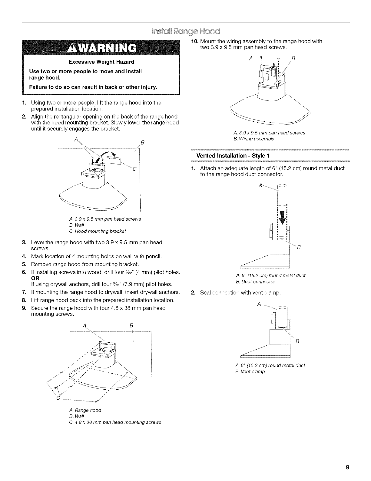
Excessive Weight Hazard
Use two or more people to move and install
range hood.
Failure to do so can result in back or other injury.
4. Using 2 or more people, lift range hood onto covered surface.
5. Determine and mark the centerline on the wall where the
range hood will be installed.Mark location of mounting
bracket on wall section using the dimensions shown.
A
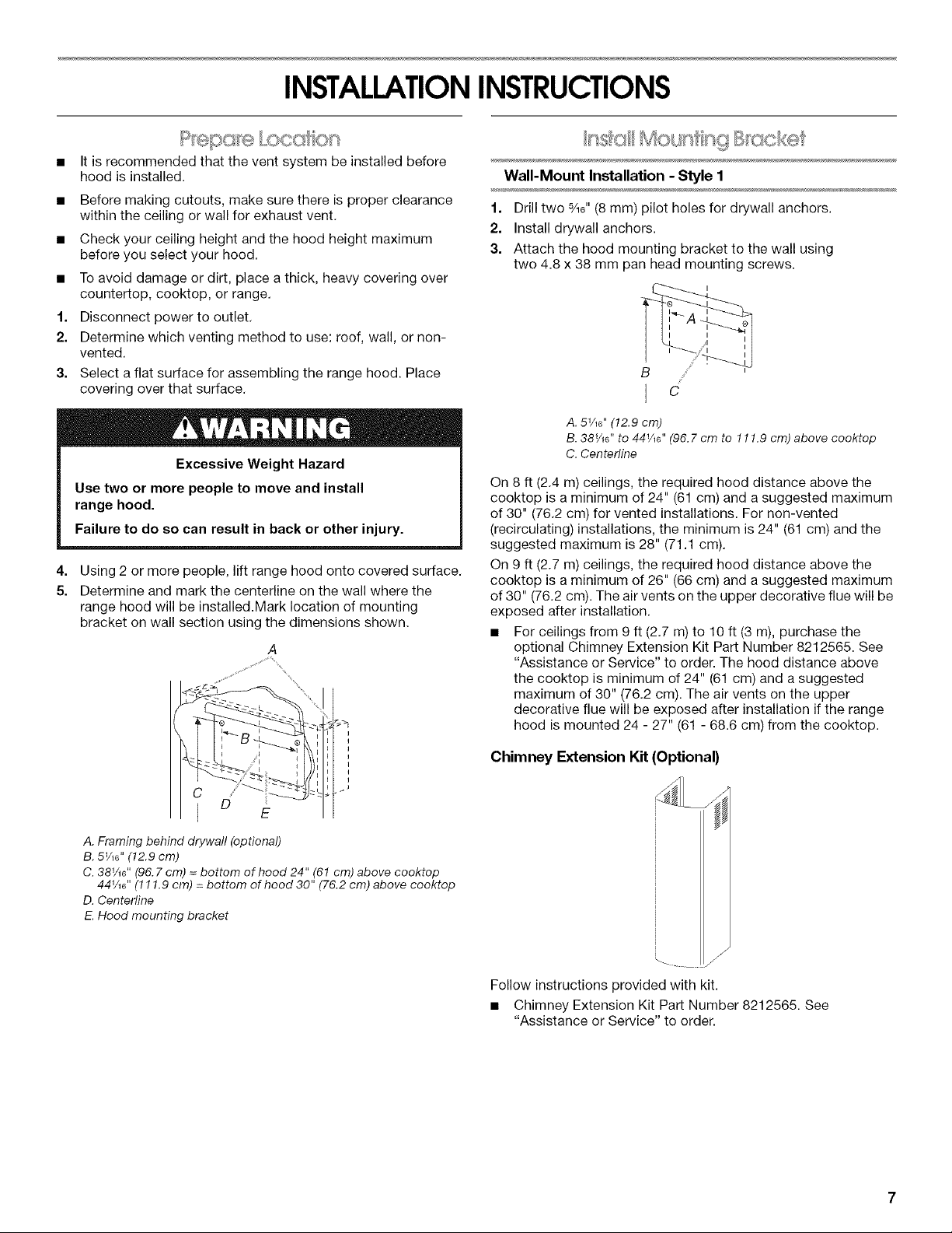
Wall-Mount Installation - Style 1
1. Drill two sA6"(8 mm) pilot holes for drywall anchors.
2. Install drywall anchors.
3. Attach the hood mounting bracket to the wall using
two 4.8 x 38 mm pan head mounting screws.
A. 5_Ae'' (12.9 cm)
B. 38V_6" to 44V_6" (96. 7 cm to 111.9 cm) above cooktop
C. Centerline
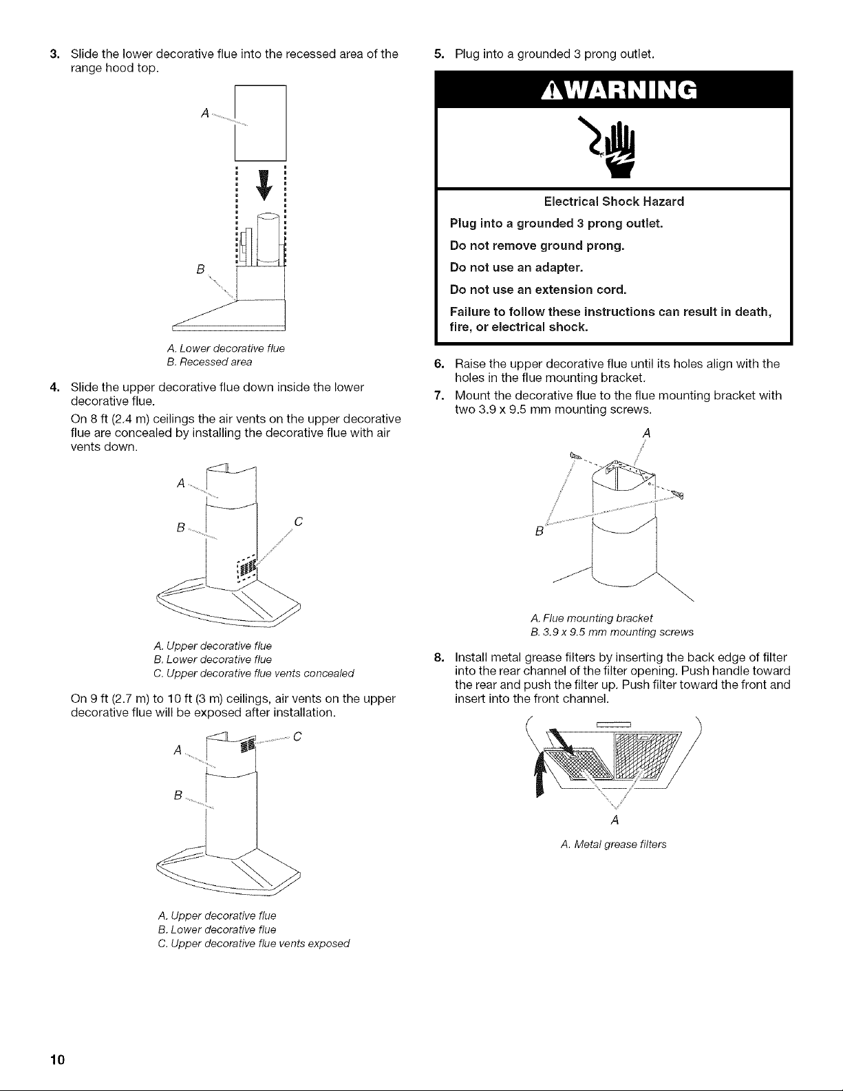
On 8 ft (2.4 m) ceilings, the required hood distance above the
cooktop is a minimum of 24" (61 cm) and a suggested maximum
of 30" (76.2 cm) for vented installations. For non-vented
(recirculating) installations, the minimum is 24" (61 cm) and the
suggested maximum is 28" (71.1 cm).
On 9 ft (2.7 m) ceilings, the required hood distance above the
cooktop is a minimum of 26" (66 cm) and a suggested maximum
of 30" (76.2 cm). The air vents on the upper decorative flue will be
exposed after installation.
• For ceilings from 9 ft (2.7 m) to 10 ft (3 m), purchase the
optional Chimney Extension Kit Part Number 8212565. See
"Assistance or Service" to order. The hood distance above
the cooktop is minimum of 24" (61 cm) and a suggested
maximum of 30" (76.2 cm). The air vents on the upper
decorative flue will be exposed after installation if the range
hood is mounted 24 - 27" (61 - 68.6 cm) from the cooktop.
A. Framing behind drywall (optional)
B. 51A6'' (12.9 cm)
C. 38V_6"(96. 7 cm) = bottom of hood 24" (61 cm) above cooktop
44V_6"(111.9 cm) = bottom of hood 30" (76.2 cm) above cooktop
D. Centerline
E.Hood mounting bracket
Chimney Extension Kit (Optional)
Follow instructions provided with kit.
• Chimney Extension Kit Part Number 8212565. See
"Assistance or Service" to order.
Wood Frame Installation - Style 2
(optional before drywall installation)
Construct wood wall framing so that it is flush with interior
surface of wall studs. The framing must be centered over the
installation location. The height of the framing must allow for
the mounting bracket to be secured to the framing within the
dimensions shown.
A. 5V_e"(12.9 cm)
B. 38V_6" to 44V_" (96. 7 cm to 111.9 cm) above cooktop
C. Centerfine
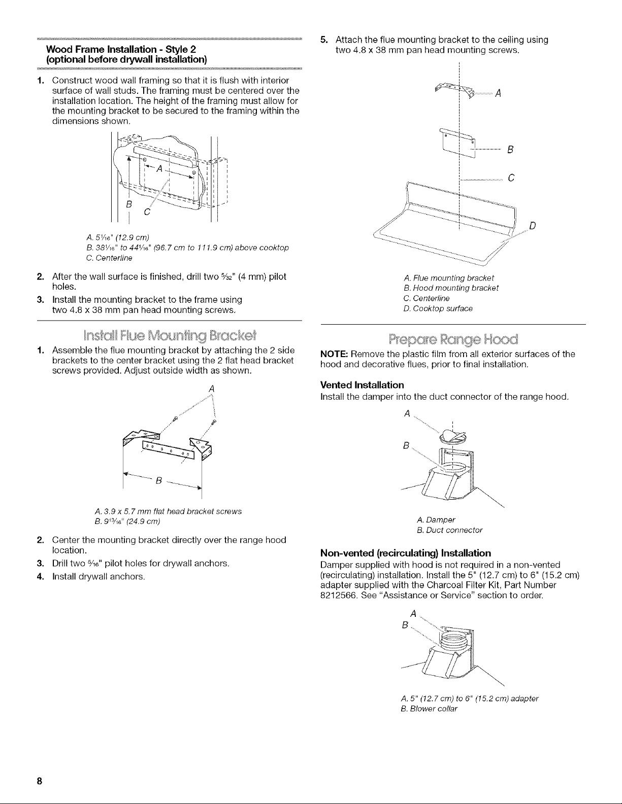
5. Attach the flue mounting bracket to the ceiling using
two 4.8 x 38 mm pan head mounting screws.
A
C
il_ _
" i D
2. After the wall surface is finished, drill two %2" (4 mm) pilot
holes.
3. Install the mounting bracket to the frame using
two 4.8 x 38 mm pan head mounting screws.
.... _ (,_<:c_ .......
Assemble the flue mounting bracket by attaching the 2 side
brackets to the center bracket using the 2 flat head bracket
screws provided. Adjust outside width as shown,
,/ /"
A. 3.9 x 5. 7 mm flat head bracket screws
B. 9W_6" (24.9 cm)
2. Center the mounting bracket directly over the range hood
location.
3. Drill two s/_6"pilot holes for drywall anchors.
4. Install drywall anchors.
A. Flue mounting bracket
B. Hood mounting bracket
C. Centerline
D. Cooktop surface
NOTE: Remove the plastic film from all exterior surfaces of the
hood and decorative flues, prior to final installation,
Vented Installation
Installthe damper into the duct connector of the range hood.
A
i
B
A. Damper
B. Duct connector
Non-vented (recirculating) Installation
Damper supplied with hood is not required in a non-vented
(recirculating) installation. Install the 5" (12.7 cm) to 6" (15.2 cm)
adapter supplied with the Charcoal Filter Kit, Part Number
8212566. See "Assistance or Service" section to order.
A
A. 5" (12.7 cm) to 6" (15.2 cm) adapter
B. Blower collar
 Loading...