

Whirlpool GZ8330XLS, GZ8336XLS Installation Instructions and Use and Care Guide
Installation Instructions and
Use and Care Guide
IMPORTANT:
Read and save
these instructions.
IMPORTANT:
Installer: Leave Installation Instructions with
the homeowner.
Homeowner: Keep Installation Instructions for
future reference.
Save Installation Instructions for local electrical
inspector's use.
99043793A/9763373
www.whirlpool.com
Quick Reference
Table of Contents:
Pages
Before you start
Electrical requirements
Product dimensions
Venting requirements
Installation steps
Use and Care Information
Warranty
Requesting Assistance
or Service
2
2
3
3 - 4
4 - 7
7 - 8
8
9- 10
30" (76.2 cm) and 36" (91.4 cm)
Convertible Range Hood
GZ8330 Series
GZ8336 Series
2
Before you start...
Proper installation is your
responsibility. Make sure you have
everything necessary for correct
installation. It is the responsibility of
the installer to comply with the
clearances specified.
Check the location where the range
hood will be installed. The location
should be away from strong draft
areas, such as windows, doors, and
strong heating vents.
Mobile home installation
The installation of this range hood
must conform to the Manufactured
Home Construction Safety
Standards, Title 24 CFR, Part 328
(formerly the Federal Standard for
Mobile Home Construction and
Safety, Title 24, HUD, Part 280) or
when such standard is not
applicable, the Standard for
Manufactured Home Installation
1982 (Manufactured Home Sites,
Communities and Setups) ANSI
A225.1/NFPA 501A*, or latest edition,
or with local codes.
Important: Observe all governing
codes and ordinances.
This is the safety alert symbol.
This symbol alerts you to
potential hazards that can kill
or hurt you and others. All safety
messages will follow the safety alert
symbol and either the word “DANGER”
or “WARNING”. These words mean:
You can be killed or seriously injured
if you don’t follow instructions.
DANGER
WARNING
Your safety and the safety of
others is very important.
We have provided many important
safety messages in this manual and
on your appliance. Always read and
obey all safety messages.
All safety messages will tell you what
the potential hazard is, tell you how to
reduce the chance of injury, and tell
you what can happen if the
instructions are not followed.
You can be killed or seriously injured
if you don’t immediately
follow
instructions.
Tools and
materials needed
for installation:
WARNING — TO REDUCE THE
RISK OF FIRE, ELECTRIC
SHOCK, OR INJURY TO
PERSONS, OBSERVE THE
FOLLOWING:
Installation work and electrical
wiring must be done by qualified
person(s) in accordance with all
applicable Codes and Standards,
including Fire Rated Construction.
Sufficient air is needed for proper
combustion and exhausting of
gases through the flue (chimney)
of fuel burning equipment to
prevent back drafting. Follow the
heating equipment
manufacturer’s guideline and
safety standards such as those
published by the National Fire
Protection Association (NFPA),
and the American Society of
Heating Refrigeration and Air
Conditioning Engineers
(ASHRAE), and the local code
authorities.
When cutting or drilling into wall or
ceiling, do not damage electrical
wiring and other hidden utilities.
Ducted fans must always be
vented to the outdoors.
WARNING — To reduce the risk
of fire, use only metal ductwork.
This unit must be grounded.
• flat blade
screwdriver
• pliers
• drill
• ruler
• 1-1/4" (3.0 cm)
drill bit
• 1/8" (or 3 mm) drill
bit for pilot holes
• pencil
Parts supplied:
• 2, aluminum filters
• 3-1/4" x 10" (8.3 x 25.4 cm) damper/vent
connector
• parts bag
Electrical
requirements
Important: Observe all governing
codes and ordinances.
It is the customer’s responsibility:
• To contact a qualified electrical
installer.
• To assure that the electrical
installation is adequate and in
conformance with National
Electrical Code, ANSI/NFPA 70
— latest edition*, or CSA
Standards C22.1-94, Canadian
Electrical Code, Part 1 and
C22.2 No.0-M91 - latest
edition** and all local codes
and ordinances.
A separate ground wire must be
used. It is recommended that a
qualified electrician determine that
the ground path is adequate.
A 120-volt, 60-Hz, AC-only, fused
electrical system is required. A
separate 15-amp circuit is
recommended.
Do not ground to a gas pipe.
Check with a qualified electrician if
you are not sure range hood is
properly grounded.
Do not have a fuse in the neutral or
ground circuit.
IMPORTANT:
Save Installation Instructions for
electrical inspector’s use.
The range hood must be connected
with copper wire only.
The range hood should be
connected directly to the fused
disconnect (or circuit breaker) box
through flexible armored or
nonmetallic sheathed copper cable.
A U.L.- or C.S.A.-listed strain relief
must be provided at each end of the
power supply cable. Wire sizes
(COPPER WIRE ONLY) and
connections must conform with the
rating of the appliance as specified
on the model/serial rating plate.
This hood is factory set for vented
installations. For non-vented
installations, purchase Charcoal
Filter Pad Kit No. 4396390 (contains
two filter pads) from your dealer.
Cabinets with recessed bottoms:
• 2, 2" (5.8 cm) wide filler strips. Length and
thickness determined by recess dimensions.
• 4 flat head wood screws or machine screws
with washers and nuts to attach filler strips.
For vented installations, you also need:
• compass or 8"
(20.3 cm) circle
template
• metal snips
• keyhole saw
• saber saw
• duct tape
• 3-1/4"x10" (81.3 x 25.4 cm)
to 6" (15.2 cm) round
transition piece if using
round vent
• 6" (15.2 cm) round damper
if using 6" (15.2 cm) round
vent system
3
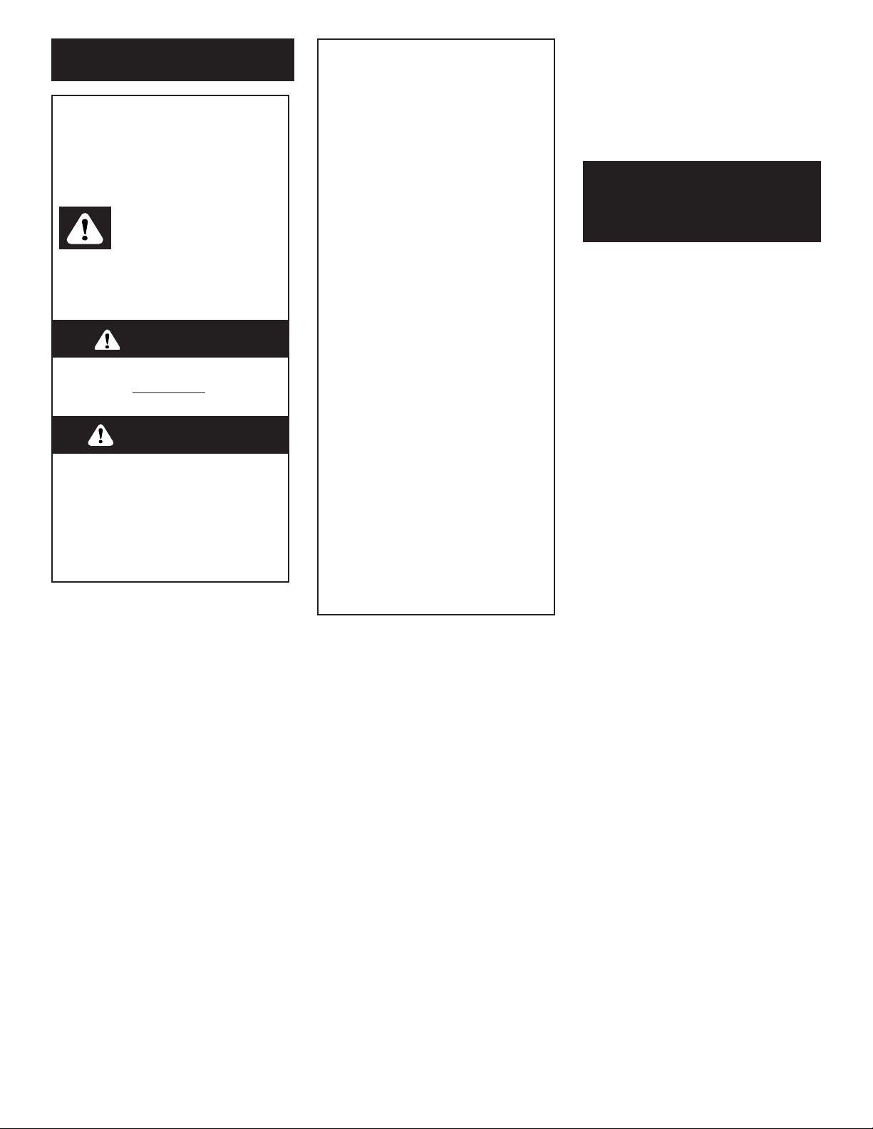
Product dimensions
Venting requirements
29-7/8" (75.9 cm) model: GZ8330
35-7/8" (91.1 cm) model: GZ8336
7-1/2"
(19.1 cm)
2"
(5.1 cm)
1-1/2"
(3.8 cm)
1"
(2.5 cm)
1-1/2"
(3.8 cm)
9"
(22.9 cm)
9"
(22.9 cm)
12"
(30.5 cm)
3/4"
(1.9 cm)
3/8"
(9.5 mm)
20"
(50.8 cm)
Wire sizes must conform to the
requirements of the National
Electrical Code ANSI/NFPA 70 —
latest edition*, or CSA Standards
C22.1-94, Canadian Electrical Code
Part 1 and C22.2 No. 0-M91 - latest
edition** and all local codes and
ordinances.
A U.L.- or C.S.A.-listed conduit
connector must be provided at each
end of the power supply cable (at
the range hood and at the junction
box).
In U.S. only: For power cord
connected installations, a U.L.listed range hood cord-connection
kit MUST be used. Cord kit has not
been evaluated for use in Canada.
Copies of the standards listed may be
obtained from:
* National Fire Protection Association
One Batterymarch Park
Quincy, Massachusetts 02269
** CSA International
8501 East Pleasant Valley Road
Cleveland, Ohio 44131-5575
Venting system must terminate to
the outside.
Do not terminate the vent in an attic
or other enclosed space.
Do not use four-inch (10.2 cm)
laundry-type wall caps.
Do not use plastic vent.
Vent system needed for installation
is not included.
Determine which outside venting
method needs to be used. It is
recommended that the vent
system be installed before
installing the hood.
NOTE: If a non-vented
(recirculating) installation is
desired, follow instructions on
Page 5.
The length of the vent system and
number of elbows should be kept
to a minimum to provide efficient
performance. The size of the vent
system should be uniform. Do
Not install two elbows together.
Use duct tape to seal all joints in
the vent system. Vent system can
terminate either through the roof
or wall. Use caulking to seal
exterior wall or roof opening
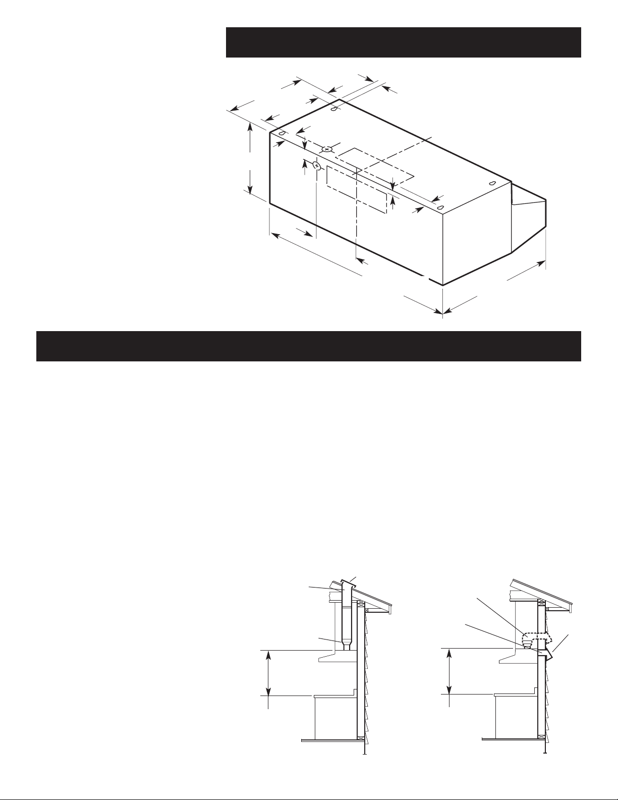
around exhaust hood. For the
most efficient and quiet operation,
it is recommended that the range
be vented vertically through the
6" (15.2 cm) or larger
round or 3-1/4" x 10"
(8.3 x 25.4 cm)
through roof
roof cap
27" (68.6 cm) to
33" (83.8 cm) above
cooking surface
transition piece
Vertical roof venting
wall
cap
3-1/4" x 10"
(8.3 x 25.4 cm)
through the wall
Horizontal wall venting
6" (15.2 cm) or larger
round or 3-1/4" x 10"
(8.3 x 25.4 cm)
through the wall
27" (68.6 cm) to
33" (83.8 cm) above
cooking surface
Figure 2
Figure 1
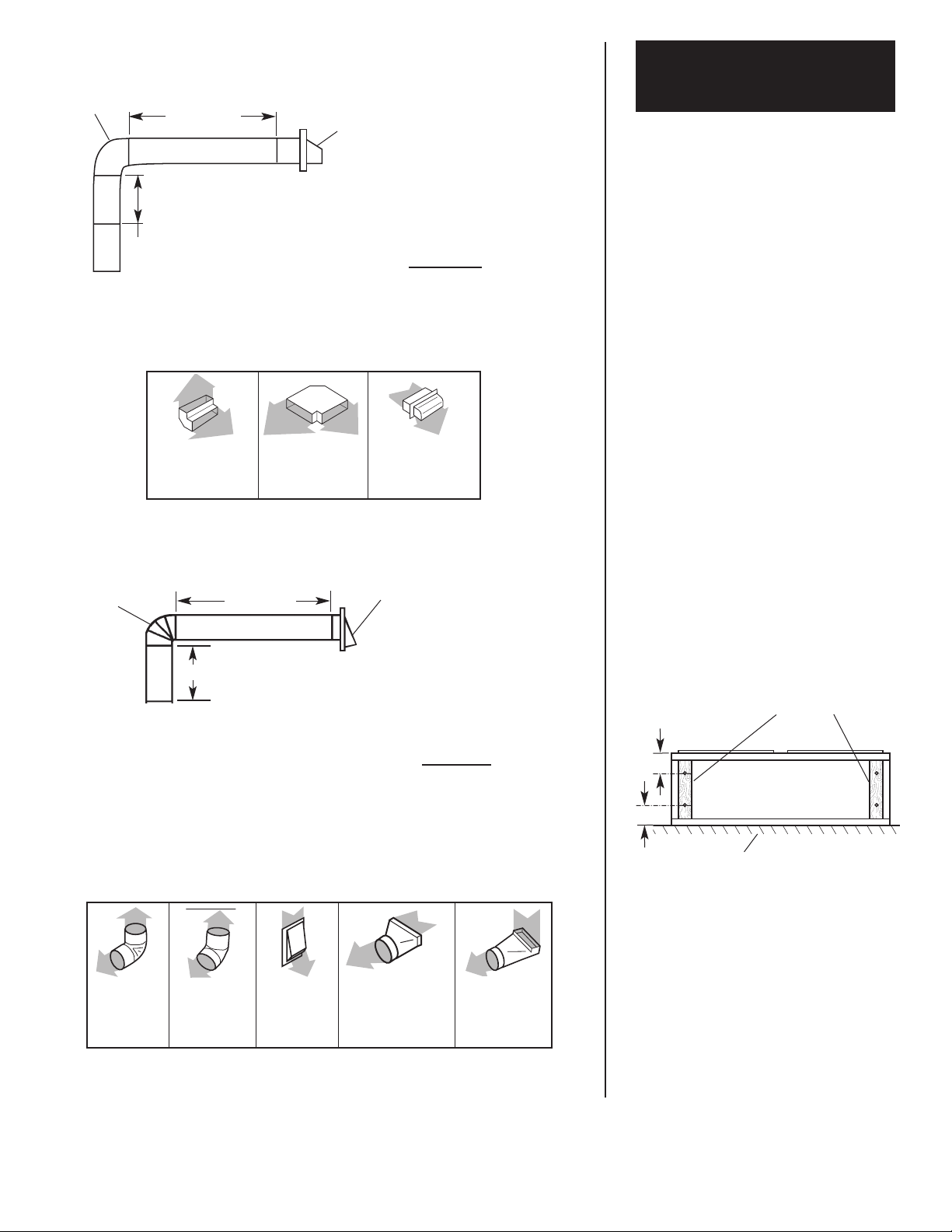
Recommended vent length
Use 3-1/4" x 10" (8.3 x 25.4 cm) or
6" (15.2 cm) or larger round vent
with a maximum length of 70 feet
(21.3 m) for vent system. If 7"
(17.8 cm) round vent is used, the
maximum length is 80 ft. (24.4 m).
For best performance, use no
more than three 90° elbows. To
calculate the length of system
you need, add the equivalent feet
(meters) for each vent piece used
in the system. See the examples
on the next page.
roof through 6" (15.2 cm) round
vent system.
Figures 1 and 2 show common
venting methods and what types
of materials are needed.
Now start...
With range hood in kitchen.
Prepare hood
location
4
3-1/4" x 10" (8.3 x 25.4 cm) vent system
Recommended standard fittings
Maximum length = 70 ft. (21.3 m)
1 - 90° elbow = 5 ft. (1.5 m)
8 ft. (2.4 m) straight = 8 ft. (2.4 m)
1 - wall cap = 0 ft. (0 m)
Length of 3-1/4" x
10" (8.3 x 25.4 cm)
system = 13 ft. (3.9 m)
3-1/4" x 10"
(8.3 x 25.4 cm)
90° elbow =
5 ft. (1.5 m)
3-1/4" x 10"
(8.3 x 25.4 cm)
flat elbow =
12 ft. (3.7 m)
3-1/4" x 10"
(8.3 x 25.4 cm)
wall cap =
0 ft. (0 m)
2 ft.
(0.6 m)
6 ft. ( 1.8 m)
wall cap
3-1/4" x 10"
(8.3 x 25.4 cm)
elbow
6" (15.2 cm) vent system
90° elbow
wall cap
Maximum length* = 70 ft. (21.3 m)
1 - 90° elbows = 5 ft.
(1.5 m)
1 - wall cap = 0 ft.
(0 m)
8 ft. (2.4 m) straight = 8 ft.
(2.4 m)
Length of 6"
(15.2 cm) system = 13 ft.
(3.9 m)
Recommended standard fittings
6 ft. (1.8 m)
2 ft. (0.6 m)
3-1/4" x 10"
(8.3 x 25.4 cm) to
6" (15.2 cm) =
4.5 ft. (1.4 m)
90° elbow =
5 ft. (1.5 m)
45° elbow =
2.5 ft. (0.8 m)
3-1/4" x 10"
(8.3 x 25.4 cm)
to 6" (15.2 cm)
90° elbow =
5 ft. (1.5 m)
6" (15.2 cm)
wall cap =
0 ft. (0 m)
Slide cardboard or hardboard under
range before moving range across
floor to prevent damaging floor
covering.
Cover countertop, cooktop or set-in
range with a thick, protective covering
to prevent damaging them.
1.
Disconnect and move
freestanding range from cabinet
opening to provide easier access
to upper cabinet and rear wall. Put
a thick, protective covering over
cooktop, set-in range or
countertop to protect from
damage or dirt.
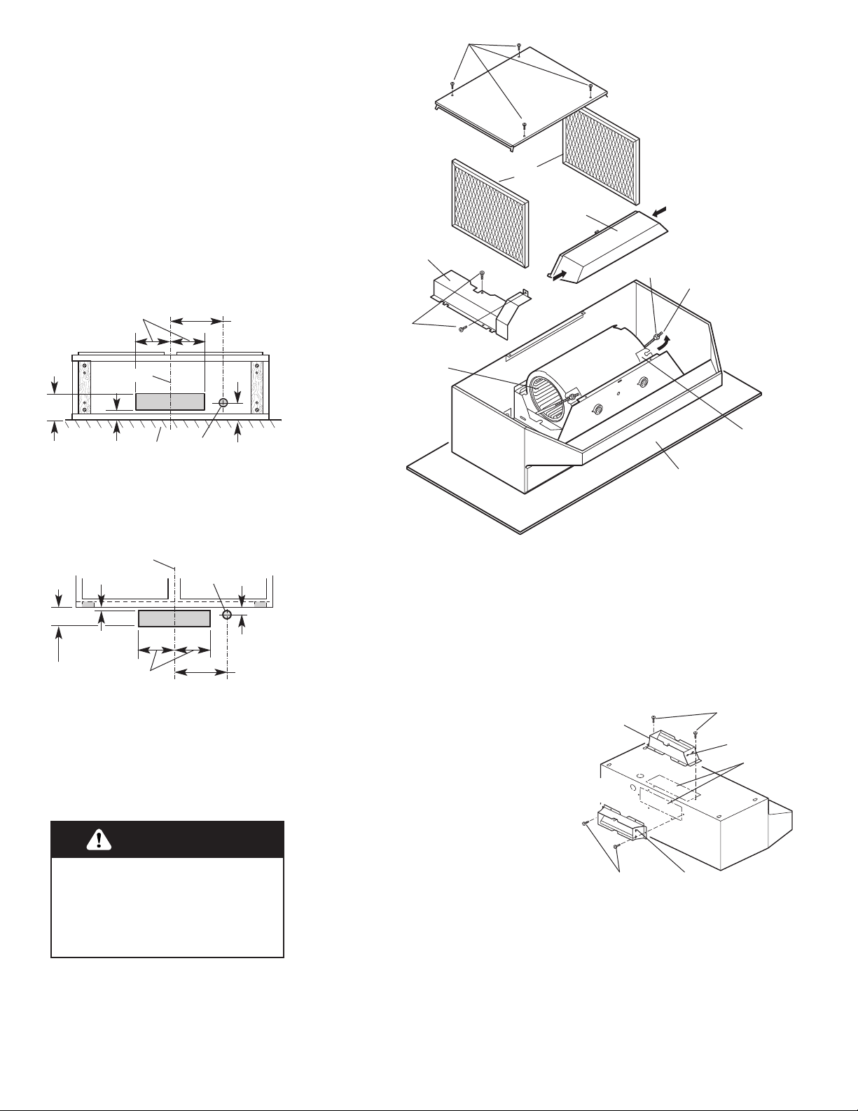
3.
If cabinet has recessed
bottom, add wood filler strips on
each side. Locate screws to attach
filler strips in locations shown.
2.
Determine which venting
method (roof or wall venting or
non-venting) you need to use. This
range hood is shipped for vented
installation.
wood filler strips
(recessed cabinet
bottoms only)
cabinet
bottom
wall
3"
(7.6 cm)
3"
(7.6 cm)
* If 7" (17.8 cm) round vent is used, maximum length of vent
system is 80 ft. (24.4 m).
Prepare and install
the hood
3-1/4" x 10" (8.3 x 25.4 cm)
RECTANGULAR VERTICAL
vent system
5
4.
From the diagrams below,
select the diagram for your
installation.
Vented installations: Cut the vent
system and electrical wiring
access holes as required. Either
wiring hole can be used.
Non-vented installations: Cut only
the one 1-1/4" (3.2 cm) dia. wiring
access hole required. If wiring
through the top, use location
shown in VERTICAL vent systems.
If wiring through the back, use
location shown in HORIZONTAL
vent system.
For Steps 5 through 10, refer to
Figure 3.
5.
Set hood upside down on a
protective covering such as
cardboard or large towel.
1-3/8"
(3.5 cm)
5-1/8"
(13.0 cm)
centerline
wall
6-1/4"
(15.9 cm)
7-1/2"
(19.1 cm)
2-1/8"
(5.4 cm)
1-1/4"
(3.2 cm)
dia. hole
3-1/4" x 10" (8.3 x 25.4 cm)
HORIZONTAL vent system
1/8"
(3.2 mm)
3-7/8"
(9.8 cm)
centerline
cabinet
front
6-1/4"
(15.9 cm)
7-1/2"
(19.1 cm)
3/4"
(19 mm)
1-1/4" (3.2 cm)
dia. hole
Excessive Weight Hazard
Use two or more people to move
and install range hood.
Failure to do so can result in
back or other injury.
WARNING
Figure 3
protective
cover
knurled
nut
mounting
rod
mounting
bracket
blower
assembly
blower
wheel
light
lens
filters
screws
bottom cover
wiring box
cover
screws
For vented installations, go to
Step 12a.
For non-vented installations,
go to Step 13.
12a.
Depending on your
installation, remove either back or
top vent knockout.
12b.
Attach the
damper/vent connector to the
hood. Use the two black sheet
metal screws provided in the
parts bag. Note: If wall cap is
directly behind vent connector,
the dampers in the connector and
wall cap MUST NOT interfere
with each other. Remove the vent
connector damper if they
interfere.
6.
Remove bottom cover
screws and bottom cover.
7.
Remove filters.
8.
Remove wiring box cover
and screws.
9.
To make the hood lighter
and easier to install, it is
recommended that the blower
assembly be removed.
To remove:
a) Disconnect blower wiring
plug.
b) Loosen, but do not remove,
knurled nuts on mounting
rods. Slip rods out of blower
mounting brackets.
Important: Do not grasp blower
by blower wheels. Wheels may
be damaged.
c) Lift blower out and set aside.
10.
Remove light lens.
Squeeze sides of lens toward
center to free lens tabs and lift
lens out.
11.
Depending on your
installation, remove either back or
top wiring knockout.
black
screws
black screws
horizontal
vent
vertical
vent
vent
knockouts
hinge pin
hinge pin
6
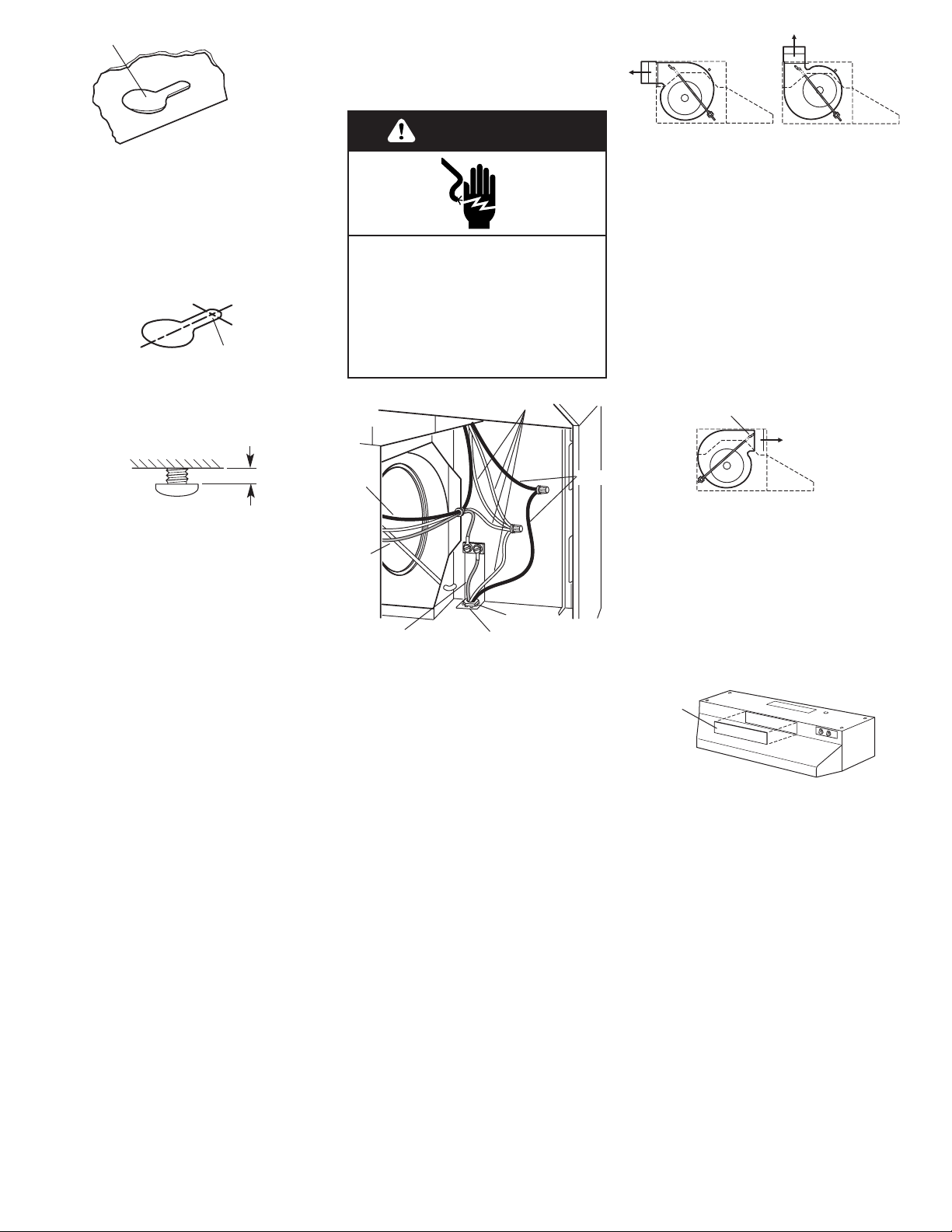
Make electrical
connection
Electrical Shock Hazard
Disconnect power before making
electrical connections.
Connect ground wire to green
ground screw in terminal box.
Failure to do so can result in
death or electrical shock.
WARNING
22.
Reinstall blower.
Vented installations:
Reinstall blower. Do not grasp
blower by blower wheels. Position
blower so that blower discharge
lines up with damper/vent
connector and slip rods into
mounting brackets on blower
assembly. Tighten knurled nuts
securely and reconnect blower
plug.
Non-vented installations:
19.
Make electrical
connections. Install locknut on
electrical connector and tighten
securely. Connect white to white
and black to black wires using
twist-on connectors. Connect
green or bare ground wire to the
green ground screw.
Using a U.L.-listed power
supply cord-connection kit
(U.S. only):
Follow Power Cord Kit instructions for
connecting wiring.
20.
Replace wiring box cover
and screws. Make sure that wires
are not pinched between cover
and hood.
21.
Install two 75 watt max.
bulbs, or one 75 watt and one 25
watt bulb for night-light use. Install
25 watt bulb in right-hand socket.
To get the most efficient
use from your new range
hood, read the “Use and
Care Information” section.
Keep your Whirlpool
Installation Instructions and
Use and Care Guide close
to range hood for easy
reference.
white
green
green or bare
ground wire
black
black
locknut
electrical
connector
horizontal vent
blower
discharge
front holes
blower
discharge
vertical vent
13.
Lift the range hood up
under cabinet and determine final
position. Mark on the underside
of cabinet the location of the four
keyhole mounting slots. Set
range hood aside on a protected
surface.
keyhole slot
front
of hood
14.
Use 1/8" (or 3 mm) drill bit
and drill 4 pilot holes as shown.
drill pilot hole
15. Remove the 4 hood
mounting screws from the parts bag
and install
in pilot holes. Leave
screw heads away from filler
strips or cabinet bottom about
1/4" (6.4 cm)
16. If using direct wiring, make
sure power is disconnected, and pull
about 12" (30 cm) of wire through
wall or cabinet and into opening.
17. Lift range hood into final
position, feeding electrical wire
through wiring opening. Position the
range hood so that the large end of
the keyhole slots are over the
screws. Then push the hood toward
the wall so that the screws are in the
neck of the slots. Tighten mounting
screws to cabinet, making sure
mounting screws are in narrow neck
of slots. Make sure that damper
blade, if used, rotates up and down
freely.
18. Connect ventwork to hood.
Seal joints with duct tape to make
the secure and air tight.
1/4"
(6.4 mm)
blower
discharge
Reinstall blower. Do not grasp
blower by blower wheels. Move
mounting rods to front holes in
hood support channels. Position
blower so that blower discharge
lines up with louvered opening on
hood front.
Slip rods into mounting brackets
and tighten knurled nuts securely.
Reconnect blower plug.
Remove louver cover on control
panel. Pry cover off with
screwdriver or knife.
23.
Reinstall bottom cover
(see Step 6).
louver
cover
 Loading...