

Whirlpool GZ7930XHS1, GZ7936XHS1, KIRD862HSS1, KIRD802HSS1 Owner’s Manual
iMPORTANT:
Read and save
these instructions.
iMPORTANT:
Installer: Leave Installation instructions with
the homeowner.
Homeowner: Keep Installation instructions for
future reference.
Save Installation Instructions for local electrical
inspector'suse.
Part No. 4329225/9763381
Quick Reference
Table of Contents:
Pages
[] Before you start
[] Electrical requirements
[] Product dimensions
[] Cabinet dimensions
[] Countertop cutout dimensions
[] Vent system requirements
Interior-mounted vent motor
[_- [] installation steps
[] Vent system requirements
Exterior-mounted vent motor
[_-[_ Installation steps
[] Use and Care information
[] Accessories
Yoursafety and the safety of
others are very important.
We have provided many important
safety messages in this manual
and on your appliance. Always
read and obey all safety
messages.
This is the safety alert
symbol.
This symbol alerts you to
potential hazards that can kill or
hurt you and others.
All safety messages will follow the
safety alert symbol and either the
word "DANGER" or "WARNING".
These words mean:
You can be killed or seriously
injured if you don't immediately
follow instructions.
You can be killed or seriously
injured if you don't follow
instructions.
All safety messages will tell you
what the potential hazard is, tell you
how to reduce the chance of injury,
and tell you what can happen if the
instructionsare not followed.
IMPORTANT: Observe all governing
codes and ordinances.
Failure to meet codes and
ordinances could lead to fire or
electrical shock.
Proper installation is your
responsibility. Make sure you have
everything necessary for correct
installation. It is the responsibility
of the installer to comply with the
installation clearances specified on
the model/serial rating plate.The
model/serial rating plate is located
on the front of the downdraft vent
above the wiring box cover.
Check location where downdraft
vent will be installed.The location
should be away from strong draft
areas, such as windows, doors and
strong heating vents or fans.
Before making countertop cutout,
check that downdraft vent and
cooktop location will clear cabinet
walls, backsplash, and rear wall
studs inside cabinet.
Mobile home installation
The installation of this downdraft
vent system must conform to the
Manufactured Home Construction
Safety Standards, Title 24 CFR,
Part 328 (formerly the Federal
Standard for Mobile Home
Construction and Safety, Title 24,
HUD, Part 280) or when such
standard is not applicable, the
Standard for Manufactured Home
Installation 1982 (Manufactured
Home Sites, Communities and
Setups) ANSI A225.1/NFPA 501A*,
or latest edition, or with local
codes.
All openings in the wall or floor
where retractable downdraft vent
is to be installed must be sealed.
Electrical ground is required. See
"Electrical requirements:' page 3.
When installing downdraft vent,
the cabinet drawer will need to be
removed and the drawer front
installed permanently to cabinet.
NOTE: Downdraft vent is installed
directly behind the cooktop. Install
downdraft vent first.
Cabinet construction: Downdraft
vent is designed for use in a
cabinet with a depth of 24"
(61 cm). Some installations
require a countertop deeper than
25" (63.5 cm). See chart on page 5.
The maximum depth of the
overhead cabinet is 13" (33 cm).
Overhead cabinets installed at
either side of the downdraft vent
must be 18" (45.7 cm) above the
cooking surface.
See cooktop Installation
Instructions before making any
cutouts and for the minimum
distance between the front edge
of the countertop and front edge
of cooktop.The minimum
horizontal distance between the
overhead cabinets is the same as
the width of the installed
downdraft vent.
When installing a 36" (91.4 cm)
retractable downdraft vent with
"Create-A-Cooktop" modules, the
optional support must be installed
on the front of the downdraft vent.
See installation steps for details.
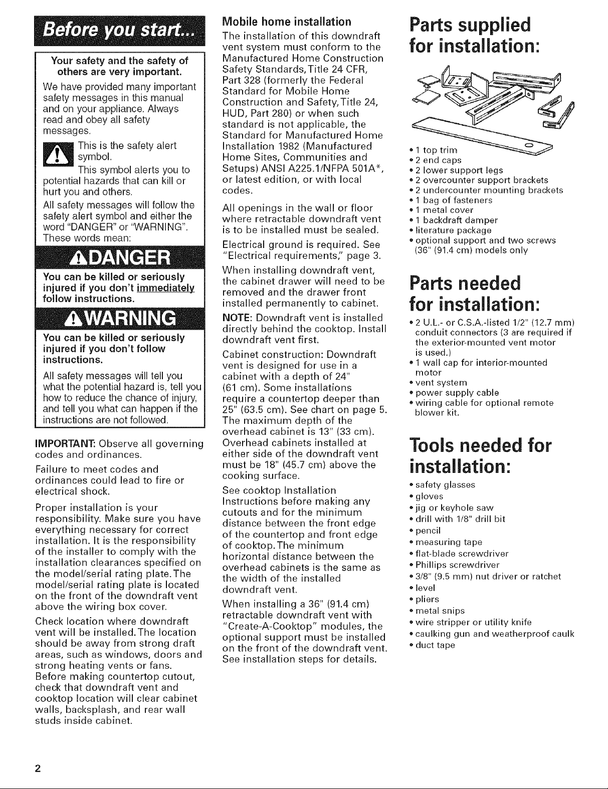
Parts supplied
for installation:
® 1 top trim
2 end caps
2 lower support legs
®2 overcounter support brackets
e 2 undercounter mounting brackets
® 1 bag of fasteners
® 1 metal cover
1 backdraft damper
® literature package
e optional support and two screws
(36" (91.4 cm) models only
Partsneeded
for installation:
®2 U.L.- or C.S.A.-listed 1/2" (12.7 ram)
conduit connectors (3 are required if
the exterior-mounted vent motor
is used.)
* 1wall cap for interior-mounted
motor
®vent system
power supply cable
wiring cable for optional remote
blower kit.
Toolsneeded for
installation:
e safety glasses
e gloves
jig or keyhole saw
,'drill with 1/8" drill bit
o pencil
® measuring tape
,'flat-blade screwdriver
Phillips screwdriver
e 3/8" (9.5 ram) nut driver or ratchet
e level
® pliers
® metal snips
®wire stripper or utility knife
®caulking gun and weatherproof caulk
e duct tape
IMPORTANT: Observe all
governing codes and ordinances.
It is the customer's responsibility:
eTo contact a qualified electrical
installer.
• To assure that the electrical
installation is adequate and in
conformance with National
Electrical Code, ANSI/NFPA 70
-- latest edition*, or CSA
Standards C22.1-g4, Canadian
Electrical Code, Part 1 and
C22.2 No. 0-M91 - latest
edition** and all local codes
and ordinances.
If codes permit and a separate
ground wire is used, it is
recommended that a qualified
electrician determine that the
ground path is adequate.
Do not ground to a gas pipe.
Check with a qualified electrician if
you are not sure downdraft vent is
properly grounded.
Do not have a fuse in the neutral
or ground circuit.
IMPORTANT: Save installation
instructions for electrical
inspector's use.
AB A 120-volt, 60-Hz, AC-only,
fused electrical supply is required
on a separate 15 amp circuit. A
time-delay fuse or circuit breaker
is recommended.The fuse must
be sized per local codes in
accordance with the electrical
rating of the downdraft vent as
specified on the model/serial
rating plate located on the front
of the downdraft vent above the
wiring box cover.
B_ The downdraft vent must
be connected with copper wire
only.
C_ Wire sizes and connections
must conform to the
requirements of the National
Electrical Code, ANSI/NFPA 70 --
latest edition*, or CSA Standards
C22.1-94, Canadian Electrical
Code, Part 1 and C22.2 No. 0-M91
- latest edition** and all local
codes and ordinances.
WARNING -- TO REDUCE THE
RISK OF FIRE, ELECTRIC
SHOCK, OR INJURY TO
PERSONS, OBSERVE THE
FOLLOWING:
installation work and electrical
wiring must be done by qualified
person(s) in accordance with all
applicable Codes and Standards,
including fire related construction.
Sufficient air is needed for proper
combustion and exhausting of
gases through the flue (chimney)
of fuel burning equipment to
prevent back drafting. Follow the
heating equipment
manufacturer's guideline and
safety standards such as those
published by the National Fire
Protection Association
(NFPA),and the American Society
of Heating Refrigeration and Air
Conditioning Engineers
(ASHRAE), and the local code
authorities.
When cutting or drilling into wall
or ceiling, do not damage
electrical wiring and other hidden
utilities.
Ducted fans must always be
vented to the outdoors.
WARNING --To reduce the risk
of fire, use only metal ductwork.
This unit must be grounded.
This downdraft vent should
be connected directly to the fused
disconnect (or circuit breaker)
through flexible, armored or non-
metallic sheathed, copper cable.
Allow some slack in the cable so
the downdraft vent can be moved
if servicing is ever necessary.
E., A U.L.- or C.S.A,-listed, 1/2"
(12.7 mm) conduit connector
must be provided at each end of
the power supply cable (at the
downdraft vent and at the
junction box).
Awiring diagram is located
on the downdraft vent base
above the wiring box cover.
Copies of the standards listed may be
obtained from:
* National Fire Protection Association
One Batterymarch Park
Quincy, Massachusetts 02269
**CSA International
8501 East PleasantValley Road
Cleveland, Ohio 44131-5575
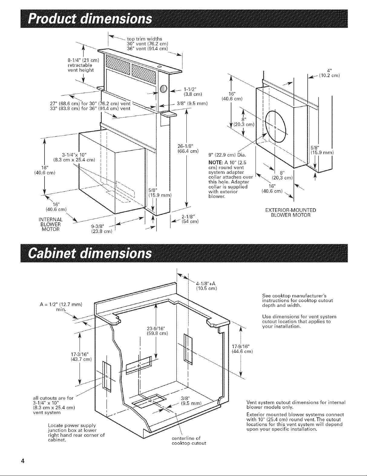
\ (15.9mm)
5/8
16"
(40.6cm) /
INTERNAL "_./_ 2-1/8"
BLOWER 9-3/8" _ _ 64 cm
MOTOR (23.8 cm)
9" (22.9 cm) Dia.
NOTE: A 10" (2.5
cm) round vent
system adapter
collar attaches over
this hole. Adapter
collar is supplied
with exterior
blower.
4 u
(10.2 cm)
6/8"
(15.9 mm)
(20,8"cm)
16" '_r_
40.6 cm ,_
EXTERIOR-MOUNTED
BLOWER MOTOR
A = 1/2" (12.7 mm)
mln.
all cutouts are for
3-1/4" x 10"
(8.3 cmx 25.4 cm)
vent system
Locate power supply
junction box at lower
right hand rear corner of
cabinet.
17-3/16"
(43.7 cm)
(10.5 cm)
See cooktop manufacturer's
instructions for cooktop cutout
depth and width.
Use dimensions for vent system
cutout location that applies to
your installation.
17-9/16"
(44.6 cm)
Vent system cutout dimensions for internal
blower models only.
Exterior mounted blower systems connect
with 10" (25.4 cm) round vent.The cutout
locations for this vent system will depend
upon your specific installation.
centerline of
cooktop cutout
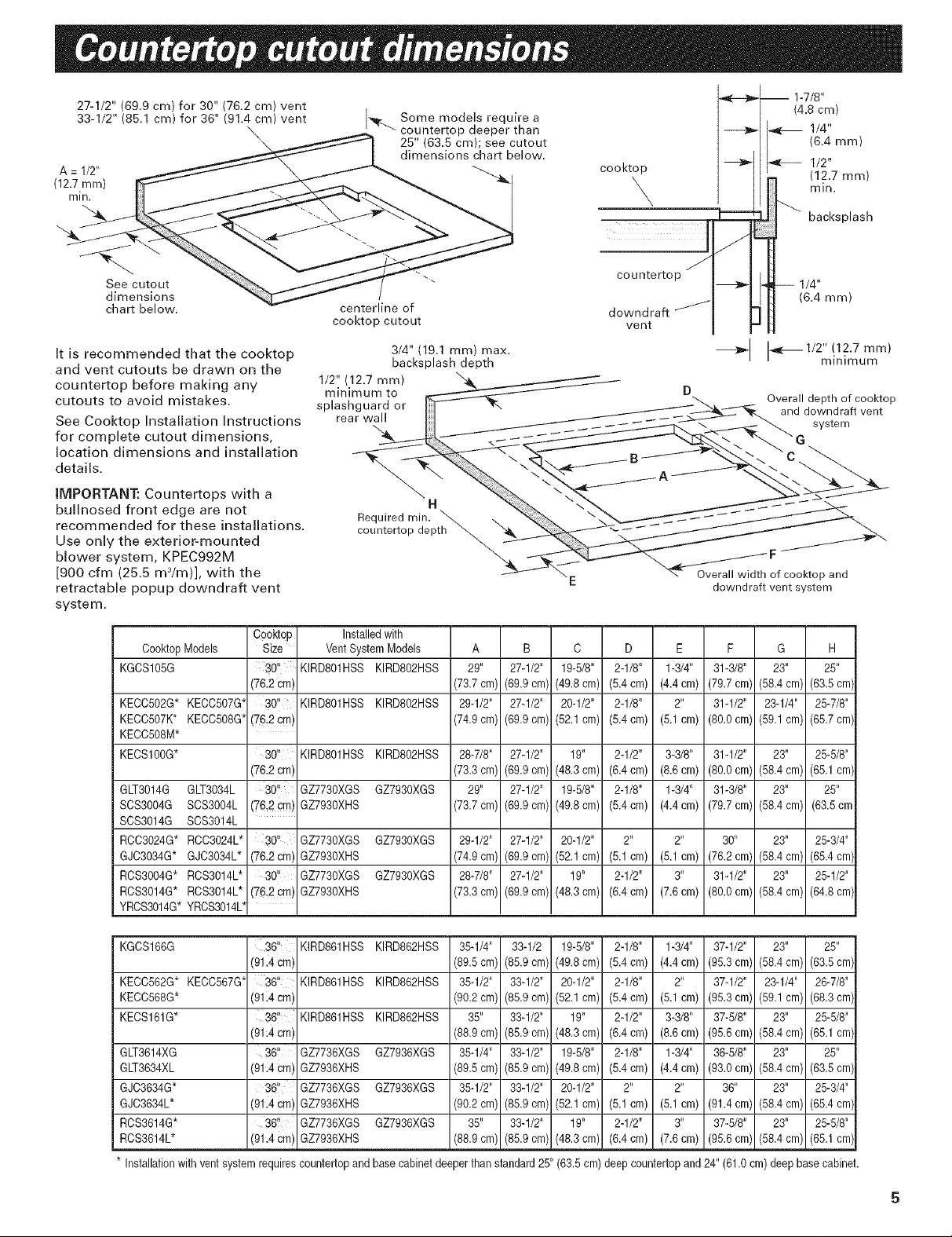
27-1/2"(69.9cm)for30"(76.2cm)vent
33-1/2"(86.1cm)for36"(91.4cm)vent
\
\
A = 1/2" cooktop
(12.7 ram) Xmin.
-,_. Some models require a
countertop deeper than
25" (63.5 cm); see cutout
dimensions chart below.
1-7/8"
(4.8 cm)
1/4"
(6.4 mm)
1/2"
(12.7 ram)
min.
backsplash
See cutout
dimensions
chart below.
It is recommended that the cooktop
and vent cutouts be drawn on the
countertop before making any
cutouts to avoid mistakes.
See Cooktop Installation Instructions
for complete cutout dimensions,
location dimensions and installation
details.
IMPORTANT." Countertops with a
bullnosed front edge are not
recommended for these installations.
Use only the exterior-mounted
blower system, KPEC992M
[900 cfm (25.5 m3/m)], with the
retractable popup downdraft vent
system.
Co0kt0p
C00kt0pModels Size
KGCS105G 30"
(76.2cm',
KECC502G* KECC507G* 30"
KECO507K* KECO508G*(76:2cm',
KECC508M*
KECS100G* 30,
(76.2cm',
GLT3014G GLT3034L 30,
SCS3004G SO83004L (762 em',
SOS3014G SOS3014L
RCO3024G* RCO3024L* 30'!
GJC3034G* GJC3034L* (76.2cm'
RCS3004G* RCS3014L* 301'
RCS3014G* RCS3014L* (76,2cm',
YROS3014G*YROS3014L
centerline of
cooktop cutout
3/4" (19.1 ram) max.
backsplash depth
1/2" (12.7 mm) \4 k
minimum to
splashguard or
rear wall
H
Required rain.
countertop depth
Installedwith
VentSystem Models
KIRD801HSS KIRDS02HSS
KIRD801HSS KIRDS02HSS
KIRD801HSS KIRDS02HSS
GZ7730XGS GZ7930XGS
GZ7930XHS
GZ7730XGS GZ7930XGS
GZ7930XHS
GZ7730XGS GZ7930XGS
GZ7930XHS
A B C
29" 27-1/2" 19-5_"
(73.7cm) (69.9cm) (49.8cm)
29-1_" 27-1/2" 20-1_"
(74.9cm) (69.9cm) (52.1cm)
28-7/8" 27-1/2" 19"
(73.3cm) (69.9cm) (48.3cm)
29" 27-1/2" 19-5/8"
(73.7cm) (69.9cm) (49.8cm)
29-1/2" 27-1/2" 20-1/2"
(74.9cm) (69.9cm) (52.1cm)
28-7/8" 27-1/2" 19"
(73.3cm) (69.9cm) (48.3cm)
countertop
downdraff
vent
D
2-1/8"
(5.4cm)
2-1/8"
(5.4cm)
2-1/2"
(6.4cm)
2-1/8"
(5.4cm)
2"
(5.1cm)
2-1/2"
(6.4cm)
J
1/4"
(6.4 mm)
--_J 1-,_-_I/2"!12.7mm)
Overall depth of cooktop
_of cooktop and
downdraft vent system
E
1-3/4"
(4.4 cm)
2"
(5.1 cm)
3-3/8"
(8.6 cm)
1-3/4"
(4.4 cm)
(5.1 cm)
3 _
(7.6 cm)
F G H
31-_8" 23" 25"
(79.7cm) (58.4cm) (63.5cm)
31-1/2" 23-1/4" 25-_8"
(80.0cm) (59.1cm) (65.7cm)
31-1/2" 23" 25-5/8"
(80.0cm) (58.4cm) (65.1cm)
31-3/8" 23" 25"
(79.7cm) (58.4cm) (63.5cm
30" 23" 25-3/4"
(76.2cm) (58.4cm) (65.4cm)
31-1/2" 23" 25-1/2"
(80.0cm) (58.4cm) (64.8cm)
minimum
and downdraft vent
system
G
KGCS166G 36" KIRD861HSS KIRD862HSS 35-1/4" 33-1/2 19-5/8"
(91.4cm', (89.5cm) (85.9cm) (49.8cm)
KECC562G* KECC567G* 36, KIRD861HSS KIRD862HSS 35-1/2" 33-1/2" 20-1/2"
KECO568G* (91i4cm' (90.2cm) (85.9cm) (52.1cm)
KECS161G* 36, KIRD861HSS KIRD862HSS 35" 33-1/2" 19"
(91i4cm' (88.9cm) (85.9cm) (48.3cm)
GLT3614XG 36" GZ7736XGS GZ7936XGS 35-1/4" 39-1/2" 19-5/8"
GLT3634XL (91.4cm', GZ7936XHS (89.5cm) (85.9cm) (49.8cm)
GJC3634G* 36, GZ7736XGS GZ7936XGS 35-1/2" 33-1/2" 20-1/2"
GJO3634L* (91.4cm', GZ7936XHS (90.2cm) (85.9cm) (52.1cm)
RCS3614G* 36, GZ7736XGS GZ7936XGS 35" 33-1/2" 19"
ROS3614L* (91.4cm' GZ7936XHS (88.9cm) (85.9cm) (48.3cm)
* Installationwith ventsystem requiresc0untert0pandbase cabinetdeeperthan standard25"(63.5 cm)
2-1/8" 1-3/4" 37-1/2" 23" 25"
(5.4cm) (4.4 cm) (95.3cm) (58.4 cm) (63.5 cm)
2-1/8" 2" 37-1/2" 23-1/4" 26-7/8"
(5.4cm) (5.1 cm) (95.3cm) (59.1 cm) (68.3 cm)
2-1/2" 3-3/8" 37-5/8" 23" 25-5/8"
(6.4cm) (8.6 cm) (95.6cm) (58.4 cm) (65.1 cm)
2-1/8" 1-3/4" 36-5/8" 23" 25"
(5.4cm) (4.4 cm) (93.0cm) (58.4 cm) (63.5 cm)
2" 2" 36" 23" 25-3/4"
(5.1cm) (5.1 cm) (91.4cm) (58.4 cm) (65.4 cm)
2-1/2" 3" 37-5/8" 23" 25-5/8"
(6.4cm) (7.6 cm) (95.6cm) (58.4 cm) (65.1 cm)
deepc0untert0pand 24" (61.0cm) deepbasecabinet.
 Loading...