

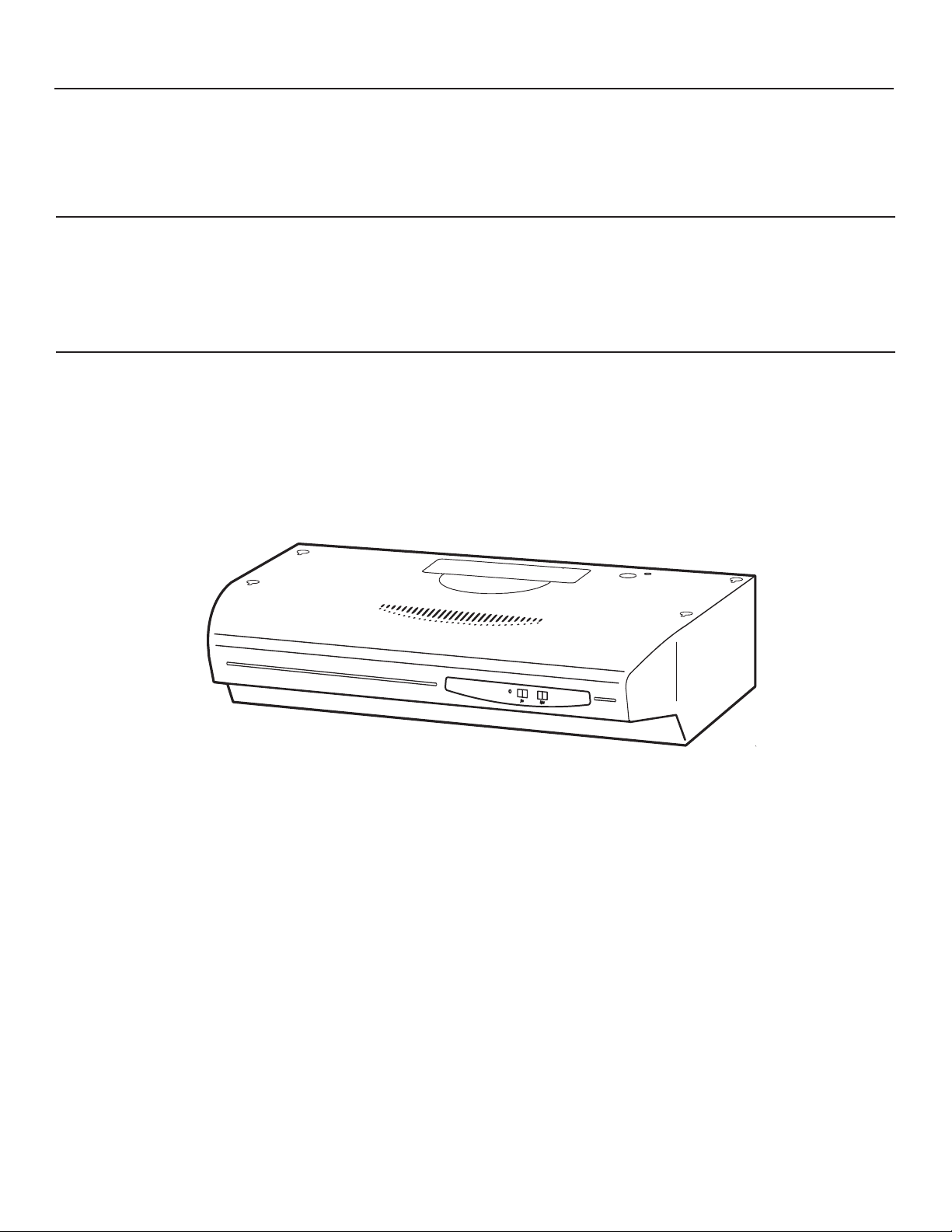
Whirlpool GZ5736XR, GZ5730XR User Manual
626953A/9761370
GZ5730XR Series
GZ5736XR Series
Série GZ5730XR
Série GZ5736XR
HOTTE DE CUISINIÈRE CONVERTIBLE
30" (76,2 cm) et 36" (91,4 cm)
Instructions d’installation et Guide d’utilisation et d’entretien
30" (76.2 cm) and 36" (91.4 cm)
CONVERTIBLE RANGE HOOD
Installation Instructions and Use and Care Guide
IMPORTANT: READ AND SAVE THESE INSTRUCTIONS.
FOR RESIDENTIAL USE ONLY.
IMPORTANT : LIRE ET CONSERVER CES INSTRUCTIONS.
POUR UTILISATION RÉSIDENTIELLE UNIQUEMENT.
IMPORTANT:
Installer: Leave installation instructions with the homeowner.
Homeowner: Keep installation instructions for future reference.
Save installation instructions for local inspector's use.
IMPORTANT :
Installateur : Remettre les instructions d'installation au propriétaire.
Propriétaire : Conserver les instructions d'installation pour consultation ultérieure.
Conserver les instructions d'installation pour consultation par l'inspecteur local.
Table of Contents/Table des matières.............................................................................2
2
RANGE HOOD SAFETY
TABLE OF CONTENTS
RANGE HOOD SAFETY . . . . . . . . . . . . . . . . . . . . . . . . . . . . . . .2
INSTALLATION REQUIREMENTS . . . . . . . . . . . . . . . . . . . . . . .4
Tools and Parts . . . . . . . . . . . . . . . . . . . . . . . . . . . . . . . . . . . . .4
Location Requirements . . . . . . . . . . . . . . . . . . . . . . . . . . . .4
Electrical Requirements . . . . . . . . . . . . . . . . . . . . . . . . . . . .4
Venting Requirements . . . . . . . . . . . . . . . . . . . . . . . . . . . . .5
INSTALLATION INSTRUCTIONS . . . . . . . . . . . . . . . . . . . . . . . .6
Prepare Location . . . . . . . . . . . . . . . . . . . . . . . . . . . . . . . . .6
Prepare the Hood . . . . . . . . . . . . . . . . . . . . . . . . . . . . . . . . .6
Make Electrical Connection . . . . . . . . . . . . . . . . . . . . . . . . .8
Install Range Hood . . . . . . . . . . . . . . . . . . . . . . . . . . . . . . . .9
Complete Installation . . . . . . . . . . . . . . . . . . . . . . . . . . . . . .9
RANGE HOOD USE . . . . . . . . . . . . . . . . . . . . . . . . . . . . . . . . . .10
Operation . . . . . . . . . . . . . . . . . . . . . . . . . . . . . . . . . . . . . .10
RANGE HOOD CARE . . . . . . . . . . . . . . . . . . . . . . . . . . . . . . . .10
Cleaning and Maintenance . . . . . . . . . . . . . . . . . . . . . . . .10
REQUESTING ASSISTANCE OR SERVICE . . . . . . . . . . . . . .11
RANGE HOOD WARRANTY . . . . . . . . . . . . . . . . . . . . . . . . . . .12
TABLE DES MATIÈRES
SÉCURITÉ DE LA HOTTE DE CUISINIÈRE . . . . . . . . . . . . . .13
EXIGENCES D'INSTALLATION . . . . . . . . . . . . . . . . . . . . . . . .15
Outillage et pièces . . . . . . . . . . . . . . . . . . . . . . . . . . . . . . . . . .15
Exigences d'emplacement . . . . . . . . . . . . . . . . . . . . . . . . .15
Spécifications électriques . . . . . . . . . . . . . . . . . . . . . . . . .16
Exigences concernant l'évacuation . . . . . . . . . . . . . . . . .16
INSTRUCTIONS D'INSTALLATION . . . . . . . . . . . . . . . . . . . . .18
Préparation de l'emplacement . . . . . . . . . . . . . . . . . . . . .18
Préparation de la hotte . . . . . . . . . . . . . . . . . . . . . . . . . . .18
Raccordement électrique . . . . . . . . . . . . . . . . . . . . . . . . . .20
Installation de la hotte de cuisinière . . . . . . . . . . . . . . . .21
Achever l'installation . . . . . . . . . . . . . . . . . . . . . . . . . . . . .21
UTILISATION DE LA HOTTE DE CUISINIÈRE . . . . . . . . . . . .22
Fonctionnement . . . . . . . . . . . . . . . . . . . . . . . . . . . . . . . . .22
ENTRETIEN DE LA HOTTE DE CUISINIÈRE . . . . . . . . . . . . .22
Nettoyage et entretien . . . . . . . . . . . . . . . . . . . . . . . . . . . .22
DEMANDE D'ASSISTANCE OU DE SERVICE . . . . . . . . . . . .23
GARANTIE DE LA HOTTE DE CUISINIÈRE . . . . . . . . . . . . . .24
You can be killed or seriously injured if you don't immediately
You
can be killed or seriously injured if you don't
follow
All safety messages will tell you what the potential hazard is, tell you how to reduce the chance of injury, and tell you what can
happen if the instructions are not followed.
Your safety and the safety of others are very important.
We have provided many important safety messages in this manual and on your appliance. Always read and obey all safety
messages.
This is the safety alert symbol.
This symbol alerts you to potential hazards that can kill or hurt you and others.
All safety messages will follow the safety alert symbol and either the word “DANGER” or “WARNING.”
These words mean:
follow instructions.
instructions.
DANGER
WARNING

3
IMPORTANT SAFETY INSTRUCTIONS
SAVE THESE INSTRUCTIONS
WARNING: TO REDUCE THE RISK OF FIRE, ELECTRIC
SHOCK, OR INJURY TO PERSONS, OBSERVE THE
FOLLOWING:
■ Use this unit only in the manner intended by the
manufacturer. If you have questions, contact the
manufacturer.
■ Before servicing or cleaning the unit, switch the power off at
the service panel disconnecting means to prevent power
from being switched on accidentally. When the service
disconnecting means cannot be locked, securely fasten a
prominent warning device, such as a tag, to the service
panel.
■ Installation work and electrical wiring must be done by
qualified person(s) in accordance with all applicable codes
& standards, including fire-rated construction.
■ Sufficient air is needed for proper combustion and
exhausting of gases through the flue (chimney) of fuel
burning equipment to prevent backdrafting. Follow the
heating equipment manufacturer's guideline and safety
standards such as those published by the National Fire
Protection Association (NFPA), the American Society for
Heating, Refrigeration and Air Conditioning Engineers
(ASHRAE), and the local code authorities.
■ When cutting or drilling into wall or ceiling; do not damage
electrical wiring and other utilities.
■ Ducted systems must always be vented outdoors.
CAUTION: For general ventilating use only. Do not use
to exhaust hazardous or explosive materials and vapors.
CAUTION: To reduce risk of fire and to properly exhaust
air, be sure to duct air outside - do not vent exhaust air into
spaces within walls ceilings, attics, crawl spaces, or
garages.
WARNING: TO REDUCE THE RISK OF FIRE, USE ONLY
METAL DUCTWORK.
WARNING: TO REDUCE THE RISK OF A RANGE TOP
GREASE FIRE:
■ Never leave the surface units unattended at high settings.
Boilovers cause smoking and greasy spillovers that may
ignite. Heat oils slowly on low or medium settings.
■ Always turn hood ON when cooking at high heat or when
flameing food (i.e. Crepes Suzette, Cherries Jubilee,
Peppercorn Beef Flambé).
■ Clean ventilating fans frequently. Grease should not be
allowed to accumulate on fan or filter.
■ Use proper pan size. Always use cookware appropriate for
the size of the surface element.
WARNING: TO REDUCE THE RISK OF INJURY TO
PERSONS IN THE EVENT OF A RANGE TOP GREASE
FIRE, OBSERVE THE FOLLOWING:
a
■ SMOTHER FLAMES with a close fitting lid, cookie sheet, or
other metal tray, then turn off the gas burner or electric
element. BE CAREFUL TO PREVENT BURNS. If the
flames do not go out immediately, EVACUATE AND CALL
THE FIRE DEPARTMENT.
■ NEVER PICK UP A FLAMING PAN - you may be burned.
■ DO NOT USE WATER, including wet dishcloths or towels -
a violent steam explosion will result.
■ Use an extinguisher ONLY if:
– You know you have a class ABC extinguisher, and you
already know how to operate it.
– The fire is small and contained in the area where it
started.
– The fire department is being called.
– You can fight the fire with your back to an exit.
a
Based on "Kitchen Fire Safety Tips" published by NFPA.
■ WARNING: To reduce the risk of fire or electrical shock,
do not use this fan with any solid-state speed control
device.
4
Location Requirements
IMPORTANT: Observe all governing codes and ordinances.
Hood location should be away from strong draft areas, such as
windows, doors and strong heating vents.
Grounded electrical outlet is required. See “Electrical
Requirements” section.
It is recommended that the hood be fastened into solid wood. If
fastening into drywall or other material, wall anchors or screws
with toggle nuts (purchased separately) must be used.
This hood is factory set for non-venting (recirculating)
installations. For vented installations see “Installation Instructions”
section.
If this hood will be used as a non-vented installation you will also
need to purchase a 30" (76.2 cm) Filter Kit, No. 4396291 or
36" (91.4 cm) Filter Kit, No. 4396292 from your dealer.
All openings in ceiling and wall where the hood will be installed
must be sealed.
In U.S. only: For power cord connected installations, a UL-listed
range hood cord-connection kit (part no. 99524057) must be
used. Cord kit has not been evaluated for use in Canada.
Tools and Parts
Gather the required tools and parts before starting installation.
Read and follow the safety instructions provided with any tools
listed here.
Tools needed:
■ level
■ compass or 8" (20.3 cm) circle template
■ flat blade screwdriver
■ Phillips screwdriver
■ pliers
■ metal snips
■ drill
■ 1¹⁄₄" and ¹⁄₈"drill bits
■ pencil
■ ruler
■ keyhole saw
■ saber saw
■ duct tape
Parts needed:
■ UL- or CSA-listed, ¹⁄₂" (12.5 mm) strain relief
(used with direct wiring only)
■ power supply cable
■ 7" (17.8 cm) round damper if using
7" (17.8 cm) round vent system
■ 2 twist-on electrical wire connectors
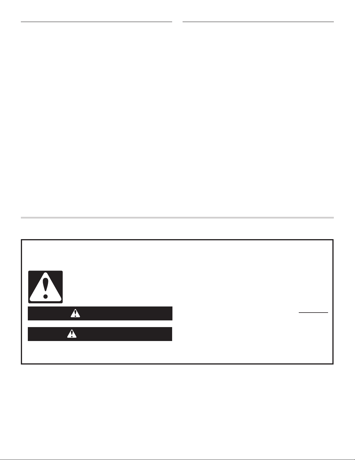
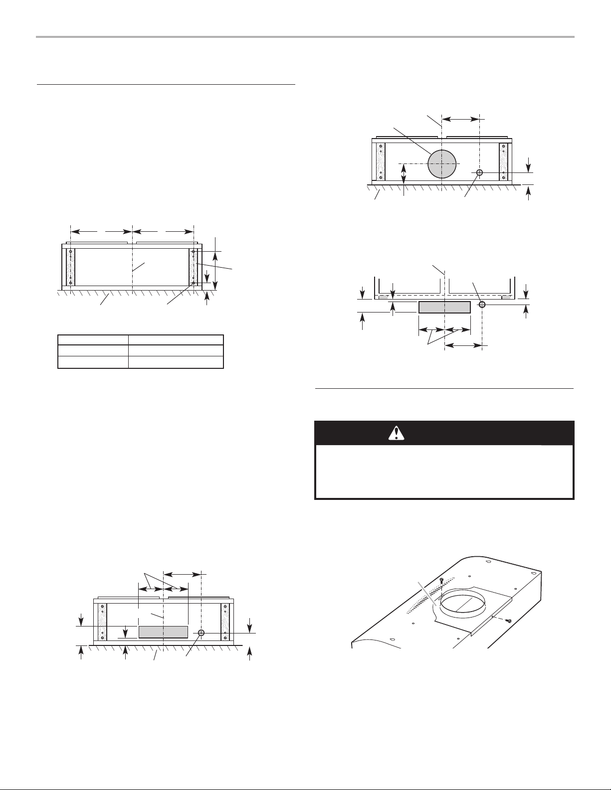
INSTALLATION REQUIREMENTS
29-7/8" (75.9 cm) model: GZ5730 Series
35-7/8" (91.1 cm) model: GZ5736 Series
7-1/4"
(18.4 cm)
20"
(50.8 cm)
12-5/8"
(32.1 cm)
Electrical Requirements
IMPORTANT: The hood must be electrically grounded in
accordance with local codes and ordinances, or in the absence of
local codes, with the National Electrical Code, ANSI/NFPA 70,
latest edition, or Canadian Electrical Code, CSA C22.1.
If codes permit and a separate ground wire is used, it is
recommended that a qualified electrical installer determine that
the ground path is adequate.
A copy of the above code standards can be obtained from:
National Fire Protection Association
One Batterymarch Park, Quincy, MA 02269
CSA International
8501 East Pleasant Valley Road
Cleveland, Ohio 44131-5575
■ A 120-volt, 60-Hz, AC-only, 15-amp, fused electrical circuit is
required. A time-delay fuse or circuit breaker is also
recommended. It is recommended that a separate circuit
serving only this hood be provided.
■ Do not ground to a gas pipe.
■ Check with a qualified electrician if you are not sure range
hood is properly grounded.
■ Do not have a fuse in the neutral or ground circuit.
■ The range hood must be connected with copper wire only.
■ The range hood should be connected directly to the fused
disconnect (or circuit breaker) box through flexible armored or
nonmetallic sheathed copper cable.
■ A UL- or CSA-listed strain relief must be provided at each end
of the power supply cable. Wire sizes (copper wire only) and
connections must conform with the rating of the appliance as
specified on the model/serial rating plate.
■ Wire sizes must conform to the requirements of the National
Electrical Code, ANSI/NFPA 70, latest edition, or CSA
Standards C22.1-94, Canadian Electrical Code, Part 1 and
C22.2 No. 0-M91, latest edition, and all local codes and
ordinances.
Product Dimensions
5
Venting Requirements
■ Vent system (if needed) for installation is not included.
■ Vent system must terminate to the outside.
■ Do not terminate the vent system in an attic or other
enclosed area.
■ Do not use 4" (10.2 cm) laundry-type wall caps.
■ Use metal vent only. Rigid metal vent is recommended. Do
not use plastic or metal foil vent.
For the most efficient and quiet operation:
■ The length of the vent system and number of elbows should
be kept to a minimum to provide efficient performance. The
size of the vent system should be uniform.
■ Do not install two elbows together.
■ Vent system can terminate either through the roof or wall.
■ For the most efficient and quiet operation, it is recommended
that the range be vented vertically through the roof through
7" (17.8 cm) round vent system.
■ Use duct tape to seal all joints in the vent system.
■ Use caulking to seal exterior wall or roof opening around
the cap.
Venting Methods
Determine which outside venting method needs to be used. It is
recommended that the vent system be installed before installing
the hood.
NOTE: If a non-vented (recirculating) installation is desired, follow
instructions in the “Make Electrical Connection” section.
Roof venting
Wall venting
7" (17.8 cm) round
or 3-1/4" x 10"
(8.3 x 25.4 cm)
through roof
roof cap
24" (61 cm) to
30" (76.2 cm)
above cooking
surface
Round vent:
Use 7" (17.8 cm)
round damper
(purchased
separately)
wall
cap
3-1/4" x 10"
(8.3 x 25.4 cm)
through the wall
7" (17.8 cm)
round
or 3-1/4" x 10"
(8.3 x 25.4 cm)
through the wall
24" (61 cm) to
30" (76.2 cm)
above cooking
surface
90° elbow
wall cap
1 — 90° elbow = 5 ft. (1.5 m)
1 — wall cap = 0 ft. (0 m)
8 ft. (2.4 m) straight = 8 ft. (2.4 m)
system length = 13 ft. (3.9 m)
6 ft. (1.8 m)
2 ft.
(0.6 m)
Example vent
system
Vent piece 7" (17.8 cm) round
45° elbow 2.5 feet
(0.8 m)
90° elbow 5.0 feet
(1.5 m)
7" (17.8 cm) 0 feet
wall cap (0 m)
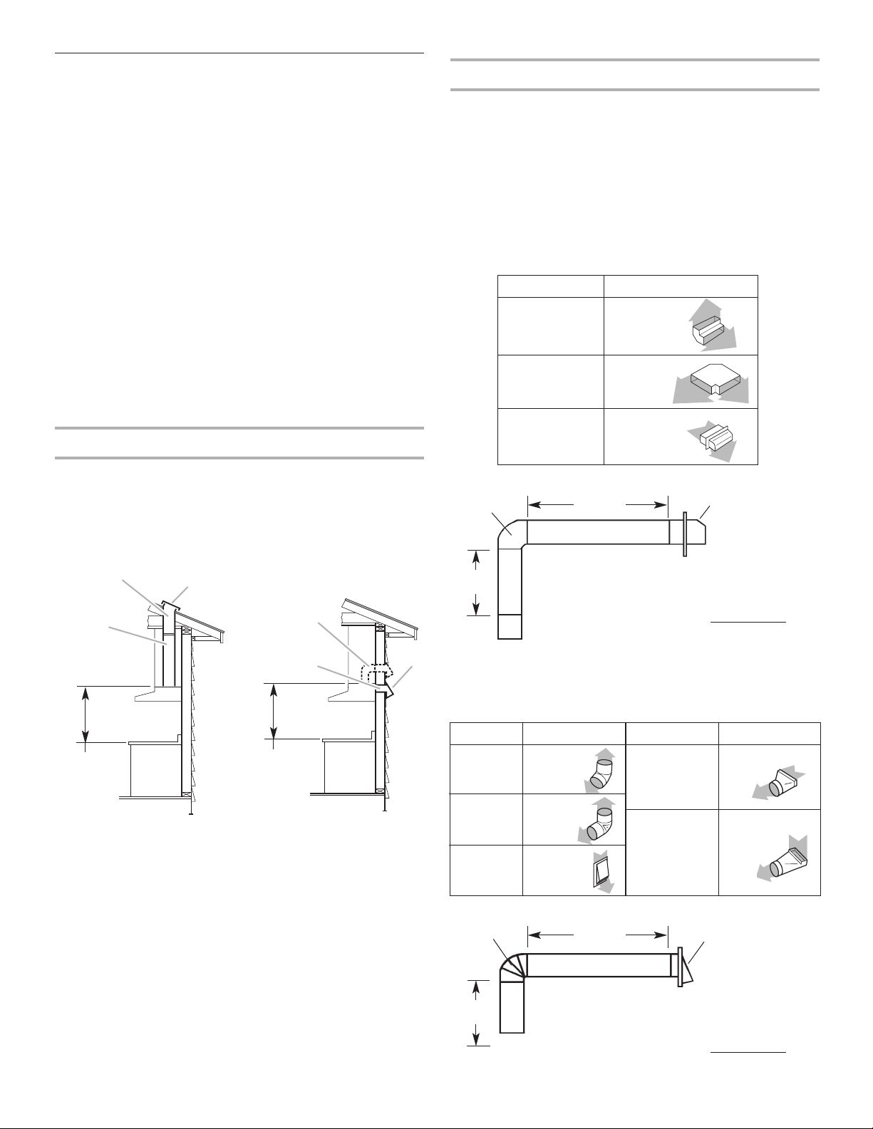
Calculating Vent System Length
To calculate the length of the system you need, add the
equivalent feet (meters) for each vent piece used in the system.
Use 3¹⁄₄" x 10" (8.3 x 25.4 cm) or 7" (17.8 cm) round vent with a
maximum length of 65 feet (19.8 m) for vent system. For best
performance, use no more than three 90° elbows. To calculate the
length of system you need, add the equivalent feet for each vent
piece used in the system. See the examples below.
3-1/4" x 10" (8.3 x 25.4 cm) vent system
7" (17.8 cm) vent system
Recommended standard fittings
Recommended standard fittings
Vent piece 7" (17.8 cm) round
3¹⁄₄" x 10"
4.5 feet
(8.3 x 25.4 cm)
(1.4 m)
to 7" (17.8 cm)
3¹⁄₄" x 10"
5 feet
(8.3 x 25.4 cm)
(1.5 m)
to 7" (17.8 cm)
90° elbow
3-1/4" x 10"
(8.3 x 25.4 cm)
elbow
wall cap
1 — 90° elbow = 5 ft. (1.5 m)
8 ft. (2.4 m) straight = 8 ft. (2.4 m)
1 — wall cap = 0 ft. (0 m)
system length = 13 ft. (3.9 m)
6 ft. (1.8 m)
2 ft.
(0.6 m)
Example vent
system
Vent piece
3¹⁄₄" x 10" (8.3 x 25.4 cm)
3¹⁄₄" x 10"
5 feet
(8.3 x 25.4 cm)
(1.5 m)
90° elbow
3¹⁄₄" x 10"
12 feet
(8.3 x 25.4 cm)
(3.7 m)
flat elbow
3¹⁄₄" x 10"
0 feet
(8.3 x 25.4 cm)
(0 m)
wall cap
6
INSTALLATION INSTRUCTIONS
Prepare Location
1. If possible, disconnect and move freestanding or slide-in
range from cabinet opening to provide easier access to upper
cabinet or rear wall. Slide cardboard or hardboard under
range before moving range across floor to prevent damaging
floor covering. Otherwise put a thick, protective covering over
countertop, cooktop or range to protect from damage
or dirt.
2. Determine which venting method (roof or wall venting or
non-venting) you need to use. This range hood is shipped for
non-vented installation.
3. Drill four ¹⁄₈" (3.0 mm) pilot holes for hood mounting screws. If
cabinet has recessed bottom, add wood shim strips on each
side.
4. From the following diagrams, select the diagram for your
installation.
Vented installations: Cut the vent system and electrical wiring
access holes as required.
Non-vented installations: Drill only the 1¹⁄₄" (3.2 cm) dia. wiring
access hole required.
■ If wiring through the top, use location shown in vertical
vent systems.
■ If wiring through the back, use location shown in
horizontal vent system.
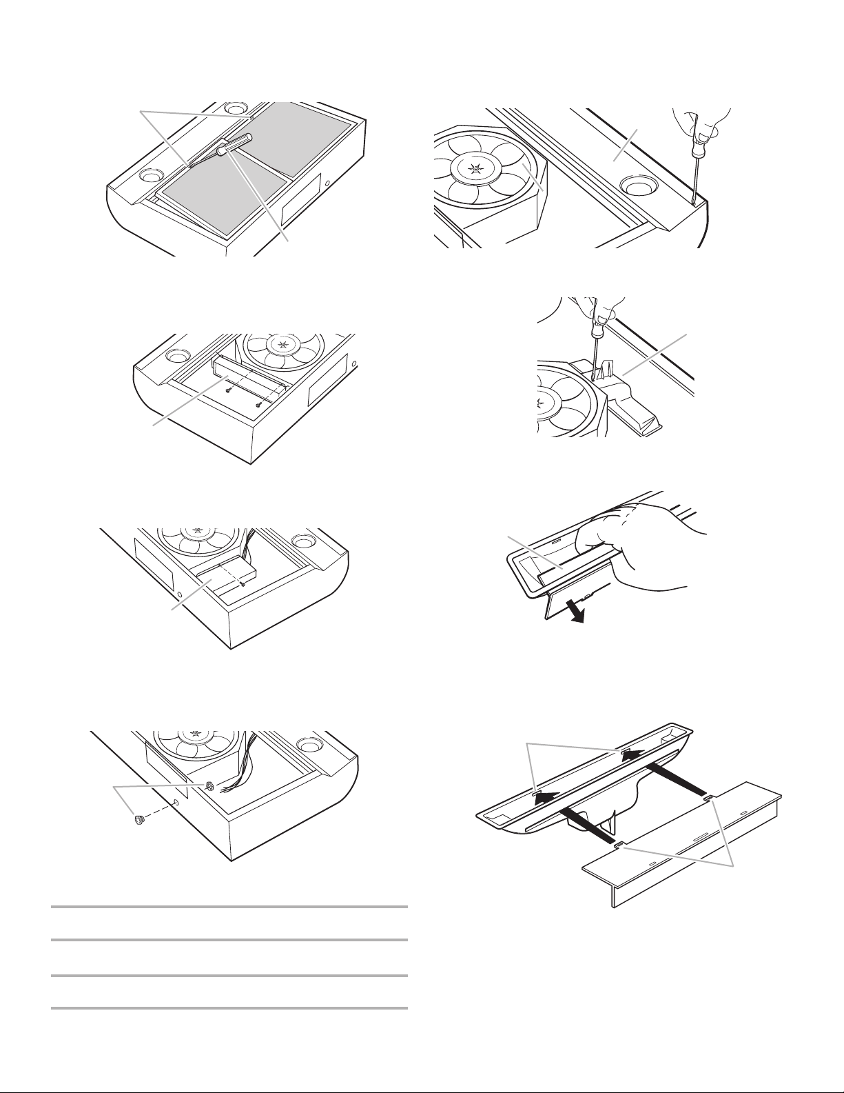
Prepare the Hood
1. Set the hood on a protective covering such as cardboard or a
large towel. Remove the 7" (17.8 cm) round vent plate from
top of hood. Set vent plate and mounting screws aside.
3¹⁄₄" x 10" (8.3 x 25.4 cm) rectangular vertical vent system
1¹⁄₄"
(3.2 cm)
5"
(12.7 cm)
centerline
wall
5¹⁄₄"
(13.3 cm)
7¹⁄₂"
(19.1 cm)
2"
(5.1 cm)
1¹⁄₄" (3.2 cm)
dia. hole
3¹⁄₄" x 10" (8.3 x 25.4 cm) horizontal vent system
¹⁄₈"
(3.2 mm)
3³⁄₄"
(9.5 cm)
centerline
cabinet front
5¹⁄₄"
(13.3 cm)
7¹⁄₂" (19.1 cm)
³⁄₄"
(19 mm)
1¹⁄₄" (3.2 cm)
dia. hole
7" (17.8 cm) round vertical vent system
5"
(12.7 cm)
centerline
wall
7¹⁄₂"
(19.1 cm)
2"
(5.1 cm)
1¹⁄₄" (3.2 cm)
dia. hole
8" (20.3 cm)
dia. hole
A
A. 7" (17.8 cm) round vent plate
10¹⁄₂"
(26.7 cm)
wood shim strips
(recessed cabinet
bottoms only)
¹⁄₈" (3.0 mm)
pilot holes
centerline
cabinet
bottom
wall
AA
1¹⁄₂"
(3.8 cm)
Hood size A
30" (76.2 cm) 13
¹⁵⁄₁₆
" (35.4 cm)
36" (91.4 cm) 16
¹⁵⁄₁₆
" (43.0 cm)
WARNING
Excessive Weight Hazard
Use two or more people to move and install range hood.
Failure to do so can result in back or other injury.
7
2. Disconnect the light assembly wiring connector.
Make sure not to disconnect any wires.
3. Remove the light panel and set aside.
4. Remove the air chute held in place with one screw.
5. Remove baffle from air chute.
6. Rotate baffle and reinsert it back into the air chute so that the
baffle tabs fit all the way into the slots in the air baffle.This will
close off the air flow through the non-vented slots on top of
the hood.
7. Replace air chute.
8. Connect light assembly wiring connector and replace light
panel.
NOTE: Make sure not to trap wires between the support fin
and light panel.
A
A. Light panel
A
A. Air chute
2. Remove tape holding standard filters in place. Remove both
filters. Insert flat blade screwdriver into slots in filters. Push
each filter toward back of hood, lift out and set aside.
3. Remove damper/vent connector from inside the hood. Set
connector, mounting screws and parts bag aside.
4. Remove wiring cover from inside the hood. Set cover and
mounting screw aside.
5. Depending on your installation, remove either top or back
wiring knockout and install a ¹⁄₂" UL- or CSA-listed strain
relief.
For non-vented installations
Go to “Make Electrical Connection” section.
For vented installations
1. Remove the five screws holding the light panel in place and
set them aside.
A
A. Damper/vent connector
A
A. Wiring cover
A
A. Strain relief
A
A. Baffle
A
B
A. Tab slots
B. Tabs
A
B
A. Filter slots
B. Flat blade screwdriver
8
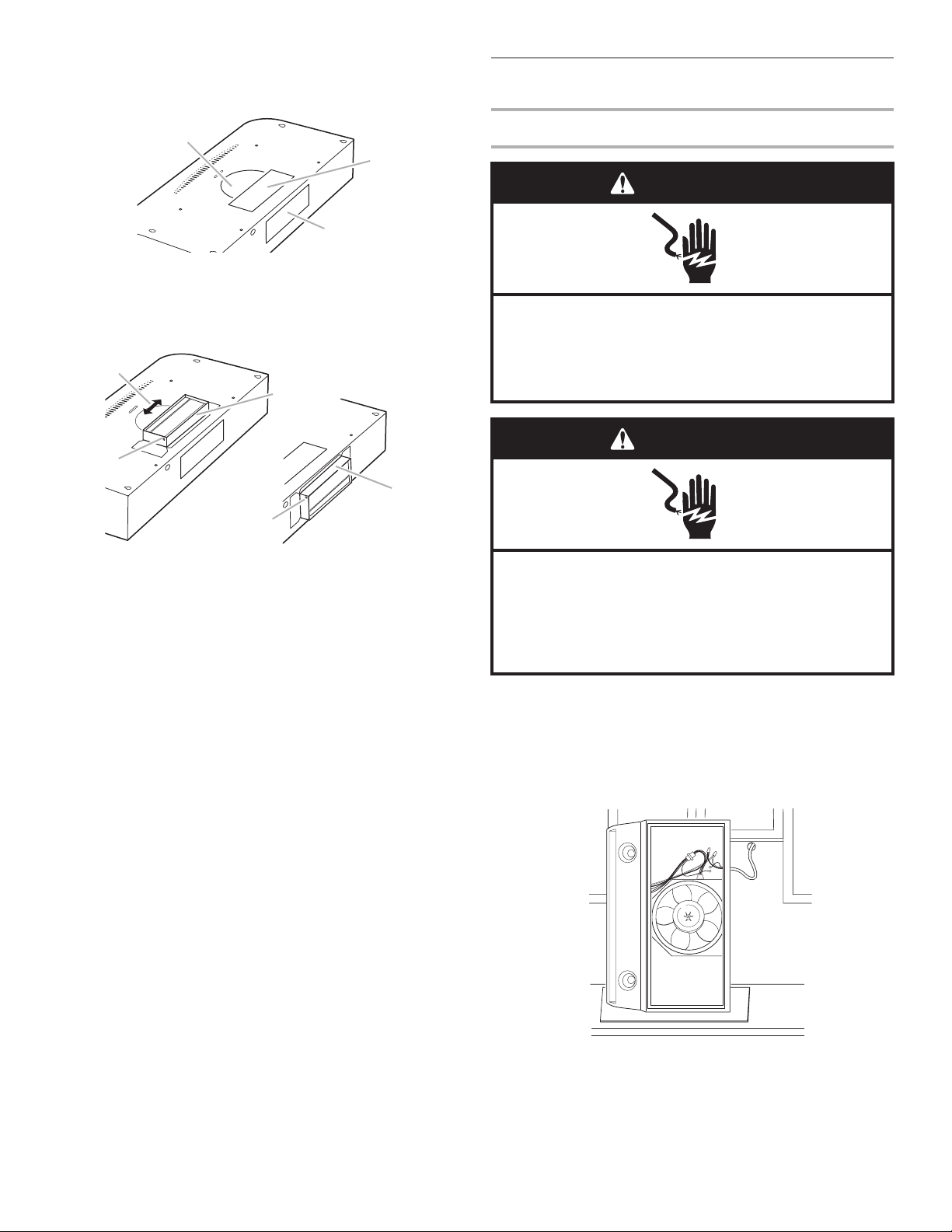
9. Remove either top or rear rectangular knockout. If using 7"
(17.8 cm) round vent, remove both top rectangular knockout
and the semi-circular knockout.
10. Install damper:
Rectangular vent only:
Attach damper/vent connector over knockout opening. Make
sure damper pivot is nearest to top/back edge of hood.
Remove tape from damper flap.
NOTE: For horizontal vent systems, it is recommended that
the rectangular ventwork be attached to the damper/vent
connector and sealed with duct tape before installing the
hood.
Round vent only:
Replace round vent plate removed in step 1 of “Prepare the
Hood” section.
Install a 7" (17.8 cm) round damper (must be purchased
separately). The damper flap must open freely in the direction
of air flow (away from range hood).
NOTE: Damper/vent connector and round vent plate can be
installed up to 1" (2.5 cm) on either side of hood center if
ventwork is off-center. In extreme off-center installations, one
end of the vent connector may need to be trimmed to clear
the electrical strain relief.
Make Electrical Connection
Direct Wiring Installation
1. Disconnect power.
2. If not previously done, run wiring through wall or cabinets
according to electrical codes and ordinances.
3. Stand hood up as shown. (Keep on protective cover to
protect hood and cooking surface.) Feed the power supply
cable through the strain relief.
4. Use twist-on connectors and connect black wires together.
5. Use twist-on connectors and connect white wires together.
WARNING
Electrical Shock Hazard
Electrically ground the blower.
Connect ground wire to green ground screw in
wiring box.
Failure to do so can result in death or electrical shock.
C
B
A
A. Semi-circular knockout
B. Top rectangular knockout
C. Rear rectangular knockout
B
A
B
C
C
Vertical vent
position
Horizontal vent
position
A. Up to 1” (2.5 cm) side-to-side adjustment
B. Pivot
C. Damper/vent connector
WARNING
Electrical Shock Hazard
Disconnect power before servicing.
Replace all parts and panels before operating.
Failure to do so can result in death or electrical shock.
 Loading...