

Whirlpool GVW9959K-0 User Manual


INTRODUCTION
This Job Aid, “ELECTRONIC CONTROL WASHER WITH CALYPSO WASH MOTION,”
(Part No. 8078010), provides specific information on the new features and design elements of
Whirlpool Electronic Control washers with Calypso Wash Motion.
“ELECTRONIC CONTROL WASHER WITH CALYPSO WASH MOTION” has been compiled to provide the most recent information on design, features, troubleshooting, service and repair procedures.
GOALS AND OBJECTIVES
The goal of this Job Aid is to provide detailed information that will enable the service technician to
properly diagnose malfunctions and repair the unique features of Whirlpool Electronic Control
washers with Calypso Wash Motion.
The objectives of the Job Aid are:
The service technician will -
• Understand proper safety precautions.
• Successfully troubleshoot and diagnose malfunction.
• Successfully perform necessary repairs.
• Successfully return the washer to proper operational status.
CORPORATIO N
WHIRLPOOL CORPORATION ASSUMES NO RESPONSIBILITY
FOR ANY REPAIRS MADE ON OUR PRODUCTS BY ANYONE
OTHER THAN AUTHORIZED SERVICE TECHNICIANS.
© 2001 Whirlpool Corporation, Benton Harbor, MI 49022

TABLE OF CONTENTS
MODEL/SERIAL PLATEMODEL/SERIAL PLATE
MODEL/SERIAL PLATE
MODEL/SERIAL PLATEMODEL/SERIAL PLATE
DESIGNATOR...............................................iiDESIGNATOR...............................................ii
DESIGNATOR...............................................ii
DESIGNATOR...............................................iiDESIGNATOR...............................................ii
Section One
INSTALLATION CONSIDERATIONSINSTALLATION CONSIDERATIONS
INSTALLATION CONSIDERATIONS
INSTALLATION CONSIDERATIONSINSTALLATION CONSIDERATIONS
USE & CARE INFORMA-USE & CARE INFORMA-
USE & CARE INFORMA-
USE & CARE INFORMA-USE & CARE INFORMA-
TION.............................................................6TION.............................................................6
TION.............................................................6
TION.............................................................6TION.............................................................6
Section Two
THEORY OF OPERATIONTHEORY OF OPERATION
THEORY OF OPERATION
THEORY OF OPERATIONTHEORY OF OPERATION
NUTATION................................................................................................7
CONTROL PANEL ...................................................................................7
CYCLE DESCRIPTIONS .........................................................................7
OPERATIONAL CYCLE DEFAULTS .......................................................8
OPTION DESCRIPTIONS........................................................................8
OPERATIONAL CYCLE NOTES ...........................................................18
CYCLE CHARTS ...................................................................................20
Section Three
COMPONENT ACCESSCOMPONENT ACCESS
COMPONENT ACCESS
COMPONENT ACCESSCOMPONENT ACCESS
COMPONENT LOCATION..................................................................... 31
ACCESSING COMPONENTS IN THE CONSOLE ................................ 32
ACCESSING COMPONENTS BENEATH THE WASHER TOP ............35
ACCESSING COMPONENTS BENEATH THE TUB ............................. 39
............................................................................
......................................
............................................................................
................................................................................
........................................
................................................................................
............................................................
..............................
............................................................
3131
31
3131
11
1
11
77
7
77
Section Four
TROUBLESHOOTING AND DIAGNOSISTROUBLESHOOTING AND DIAGNOSIS
TROUBLESHOOTING AND DIAGNOSIS
TROUBLESHOOTING AND DIAGNOSISTROUBLESHOOTING AND DIAGNOSIS
TROUBLESHOOTING CHART..............................................................43
ERROR CODES..................................................................................... 46
SELF DIAGNOSTIC ROUTINES ........................................................... 48
OVERLAY KEY MATRIX........................................................................ 53
CHECKING MOTOR CONTINUITY ....................................................... 54
TROUBLESHOOTING TESTS...............................................................55
Section Five
TECH TIPSTECH TIPS
TECH TIPS
TECH TIPSTECH TIPS
WIRING DIAGRAM ................................................................................61
COMPONENT RESISTANCE CHART ...................................................62
WARRANTY INFORMATION.................................................................62
..............................................................................................
...............................................
..............................................................................................
......................................................
...........................
......................................................
4343
43
4343
6161
61
6161
i
MODEL/SERIAL NUMBER PLATE
SERIAL NUMBER DESIGNATOR
SERIAL NUMBER
MANUFACTURING SITE
C = Clyde, OH
YEAR OF MANUFACTURE
L = 2001
WEEK OF MANUFACTURE
PRODUCT SEQUENCE NUMBER
C L 36 50001
MODEL NUMBER DESIGNATOR
MODEL NUMBER
G = Domestic Laundry Gold
L = Domestic Laundry
V = Vanguard Technology
W = Resource Saver
Cycles (1-9) 9 = 9 or more
Wash/ Spin Combinations
GW
V
9
Model/Serial
Number Plate
(Under Lid)
9
5
9
K
Q
0
5 = Water Temperature Combinations
1-5 = Water Levels
9 = Infinite Water Level
YEAR OF INTRODUCTION
J = 2000
K = 2001
Color Code
Q = White on White
T = Biscuit on Biscuit
L = Pewter
ENGINEERING CHANGE
0 = Basic Release; 1 = First Revision; 2 = Second Revision
SAFETY
! WARNING
ELECTRICAL SHOCK HAZARD
Disconnect power before servicing the washing machine.
Replace all panels before operating the washing machine.
Failure to do so can result in death or electrical shock.
ii
INSTALLATION CONSIDERATIONS
INSTALLATION
INSTRUCTIONS
Proper installation is your responsibility.
You will need
A water heater set to deliver a minimum of 120°F (49°C) water
to the washer.
SECTION ONE
National Electrical Code, ANSI/NFPA 70-latest edition and all
local codes and ordinances.
Fig. 1-1
A grounded electrical outlet located within 4 ft. (1.2 m) of where
the power cord is attached to the back of the washer. See
“Electrical Requirements.”
Hot and cold water faucets located within 4 ft. (1.2 m) of the
hot and cold water fill valves, and water pressure of 5-100 psi
(34.5-689.6 kPa.)
A level floor with a maximum slope of 1 in. (2.5 cm) under
entire washer. Installing the washer on carpeting is not
recommended.
Do not operate your washer in temperatures below 32°F (0°C).
Some water can remain in the washer and can cause damage in
low temperatures.
Electrical Requirements
! WARNING
Electrical Shock Hazard
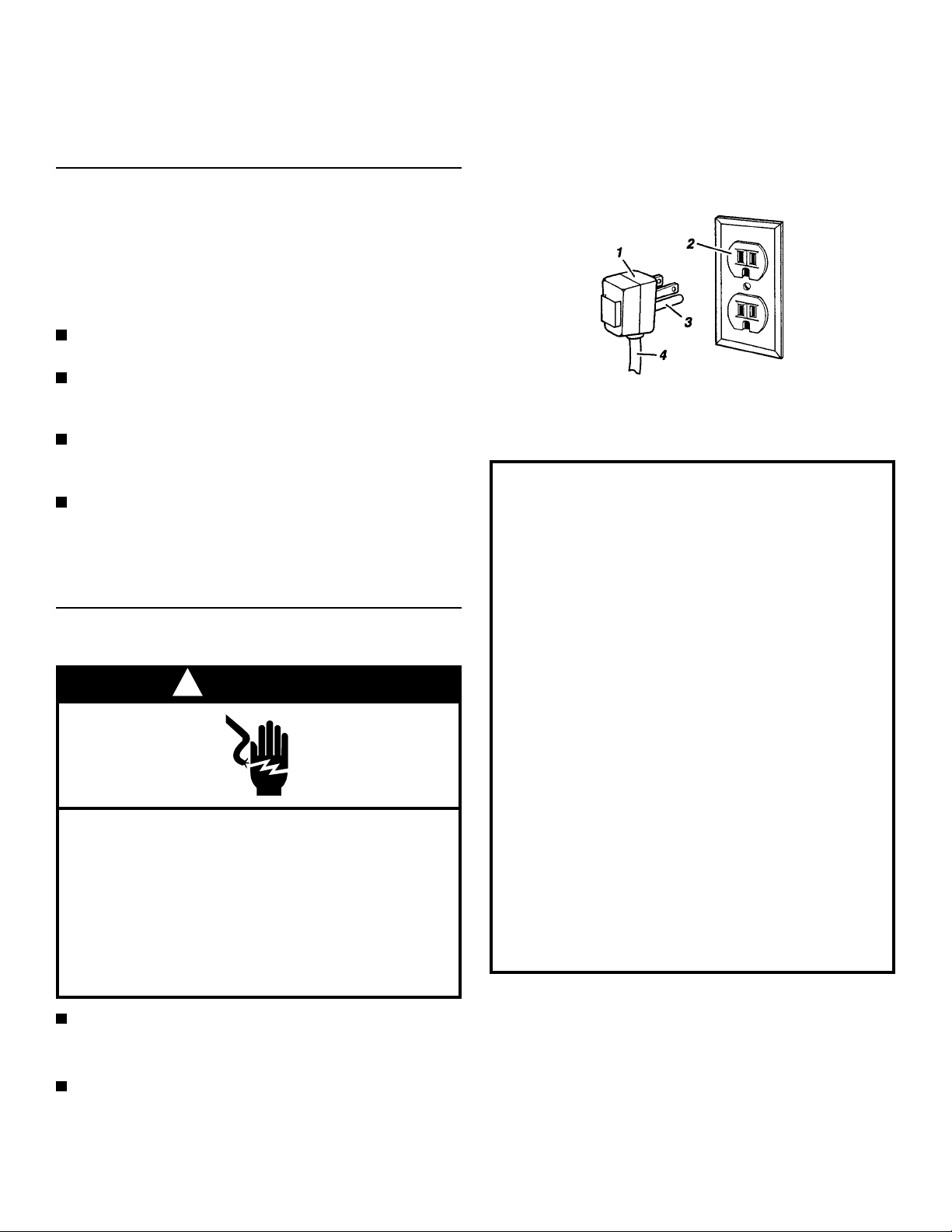
Plug into a grounded 3-prong outlet.
Do not remove ground prong.
Do not use an adapter.
Do not use an extension cord.
Failure to follow these instructions can result
in death, fire or electrical shock.
1. 3-prong grounding plug
2. 3-prong grounding-type wall receptacle
3. Grounding prong
4. Power supply cord
GROUNDING INSTRUCTIONS
For a grounded, cord-connected washer:
This washer must be grounded. In the event of a
malfunction or breakdown, grounding will reduce the risk
of electrical shock by providing a path of least resistance for electric current. This washer is equipped with
a cord having an equipment-grounding conductor and a
grounding plug. The plug must be plugged into an
appropriate outlet that is properly installed and grounded
in accordance with all local codes and ordinances.
WARNING: Improper connection of the equipment
grounding conductor can result in a risk of electric
shock. Check with a qualified electrician or serviceman
if you are in doubt as to whether the appliance is
properly grounded.
Do not modify the plug provided with the appliance - if it
will not fit the outlet, have a proper outlet installed by a
qualified electrician.
For a permanently connected washer:
This washer must be connected to a grounded metal
permanent wiring system, or an equipment grounding
conductor must be run with the circuit conductors and
connected to the equipment-grounding terminal or lead
on the appliance.
120-volt, 60 Hz, AC-only, 15 ampere fused electrical
supply is required. (Time-delay fuse or circuit breaker is
recommended.) Connect to an individual branch circuit.
This washer is equipped with a power supply cord having a 3-
prong grounding plug. To minimize possible shock hazard,
you must plug the power supply cord into a mating 3-prong
grounding-type wall receptacle, grounded in accordance with
1
Tools needed and
Parts Supplied
Assemble the necessary tools and supplies before beginning the
washer installation. Do not re-install into the washer, the
styrofoam that contains the supplied parts.
Selecting a Location
Selecting the proper location for your washer improves performance
and minimizes noise and possible washer “walk.”
Your washer can be installed in a basement, laundry room, closet
or recessed area. See “Drain System.”
To connect the drain hose and water inlet hoses
You will need these following tools
1. Flashlight (optional)
2. Pliers (that open to 1 9/16 in (3.95 cm))
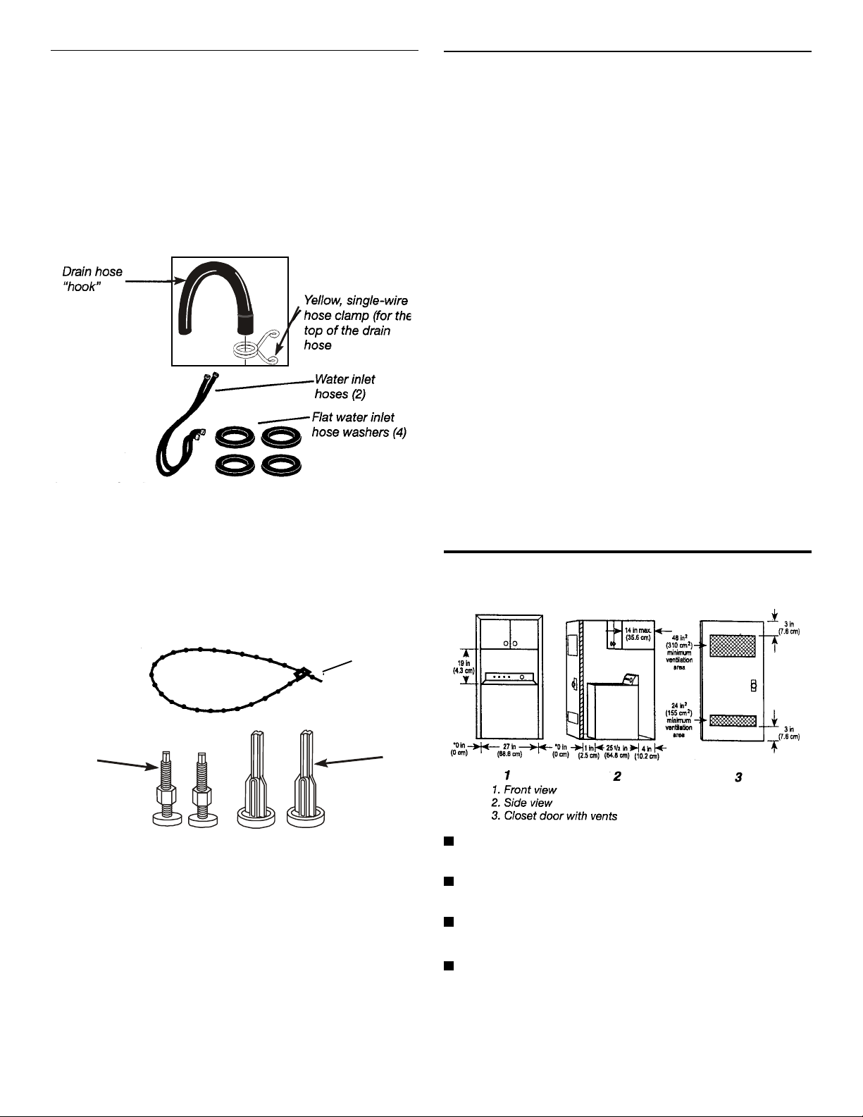
You will need the following supplied parts
Fig. 1-2
To secure the drain hose and level the washer
You will need the following tools
1. Open end wrench (9/16 in.)
2. Level
3. Wood block
4. Ruler or measuring tape
You will need the following supplied parts
Proper installation is the consumer’s responsibility.
You will need:
A water heater set to deliver a minimum 120º F. (49º C) water to
the washer.
A grounded electrical outlet located within 4 ft. of where the
power cord is attached to the back of the washer.
Hot and cold water faucets located within 4 ft. of the hot and
cold water fill valves and water pressure of 20-100 psi.
A level floor with a maximum slope of 1 inch under entire washer.
Installing the washer on carpeting is not recommended.
A sturdy floor to support the washer with a total weight (water
and load) of 315 lbs, (143kgs).
Do not operate the washer in temperatures below 32º F . (0º C).
Some water can remain in the washer and can cause damage
in low temperatures.
Recessed area or closet installation
The dimensions shown are for the minimum spacing allowed.
2
1. Tie strap with fastener
2. Front leveling feet with nuts (2)
3. Rear self-adjusting feet (2)
1
3
Fig. 1-4
Fig. 1-3
Additional spacing should be considered for ease of
installation and servicing.
Additional clearances might be required for wall, door and
floor moldings.
Additional spacing of 1 in. (2.5 cm) on all sides of the washer
is recommended to reduce noise transfer.
If a closet door is installed, the minimum air openings in the
top and bottom of the door are required. Louvered doors with
air openings in the top and bottom are acceptable.
2
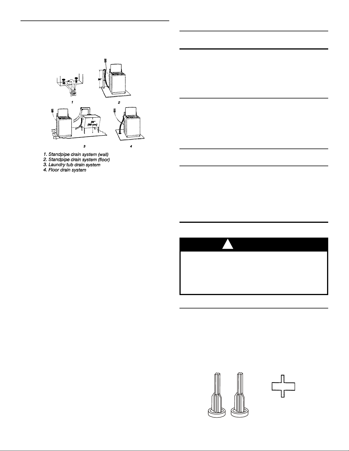
Drain System
The washer can be installed using the standpipe drain system
(floor or wall), the laundry tub drain system or the floor drain system. Select the drain hose installation method you need. See
“Alternate Parts Y ou May Need.”
Fig. 1-5
Standpipe drain system (floor or wall)
Alternate Parts You May Need
If You Have You Will Need to Buy
Laundry tub or Sump pump system (if not already
standpipe taller available)
than 96 in.
(2.4 cm)
Overhead sewer Standard 20 gal (76L) 39 in. (99 cm) tall
drain tub or utility sink and sump pump
(available from local plumbing suppliers)
Floor Drain Siphon break, Part Number 285834;
additional drain hose, Part Number
8318155 and connector kit,
Part Number 285835
Drain hose too Drain hose, Part Number 8318156 and
short connector kit, Part Number 285835
Lint clogged drain Drain protector, Part Number 367031
and connector kit, Part Number 285835
The standpipe drain requires a minimum diameter standpipe of
2 in. (5 cm). The minimum carry-away capacity can be no less
than 17 gal. (64 L) per minute.
The top of the standpipe must be at least 39 in. (99 cm) high and
no higher than 96 in. (2.4 m) from the bottom of the washer.
Laundry tub drain system
The laundry tub needs a minimum of 20 gal (76 L) capacity. The
top of the laundry tub must be at least 39 in. (99 cm) above the
floor and no higher than 96 in. (2.4 m) from the bottom of the washer.
Floor drain system
The floor drain system requires a siphon break (purchased
separately.)
The siphon break must be above the high-water level in the
washer, at least 28 in. (71 cm) from the bottom of the washer.
Water faucets 2 longer water fill hoses:
beyond reach of 6 ft. (1.8 m) Part Number 76314
fill hoses 10 ft. (3 m) Part Number 35008
Preparation
! WARNING
Excessive Weight Hazard
Use two or more people to move and install
washer.
Failure to do so can result in back or other injury.
To prevent floor damage, set the washer onto cardboard.
Installing feet
Install the rear self-adjusting feet
1. Move the washer to approximately 3 feet of the final location.
Prop up the rear of the washer about 4 in. (10.2) with a wood
block or similar object. The block needs to support the weight
of the washer. Install the self-adjusting rear feet.
The self-adjusting feet willfit into a hole, as shown below, in each
rear corner of the washer.
Fig. 1-6
3
2. Tilt the washer forward and remove the wood block. Gently
lower the washer to the floor.
3. Prop up the front of the washer about 4 in. (10.2 cm) with a
wood block or similar object. The block needs to support the
weight of the washer.
For a laundry tub drain or standpipe
Connecting the drain hose “hook” to the corrugated drain
hose
1. Open the yellow single-wire clamp and slide over the end of
the drain hose about 4 inches. (Pliers optional)
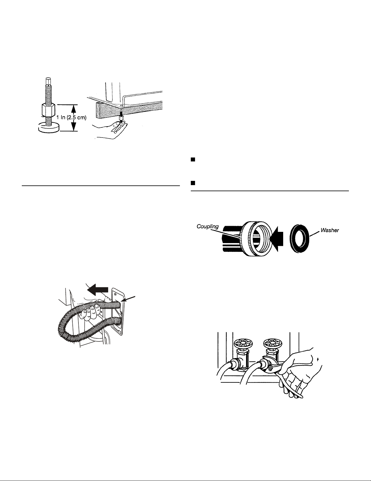
4. Screw the lock nut onto each foot to within 1 in. (2.5 cm) of the
base.
Fig. 1-7
Screw the feet into the correct holes at the front corner of the
washer until the nuts touch the washer.
NOTE: Do not tighten the nuts until the washer is level.
5. Tilt the washer back and remove the wood block. Gently lower
the washer to the floor.
Connecting the Drain Hose
Proper connection of the drain hose protects your floor from
damage due to water leakage. Carefully read and follow these instructions.
The drain hose is connected to your washer and is stored inside of
the washer cabinet.
Removing drain hose from washer cabinet
2. Wet the outside end of the drain hose with tap water. Do not
use another lubricant.
3. Twist and push the “hook” back and forth while pushing
down onto the drain hose. Continue until the “hook” is down
to the enlarged diameter of the drain hose.
4. Open the yellow single-wire clamp (placed on the drain hose
earlier) and slide over the base of the drain hose “hook” to
secure the sections together. (Pliers optional)
5. Put hooked end of drain hose into laundry tub or standpipe.
Rotate “hook” to eliminate kinks.
To prevent drain water from going back into the washer;
Do not straighten hooked end of the drain hose and force
excess drain hose into standpipe. Hose should be secure but
loose enough to provide a gap for air.
Do not lay excess hose on the bottom of the laundry tub.
Connecting the Inlet Hose
Insert a new flat washer (supplied) into each end of the inlet
hoses.
Fig. 1-9
1. Gently pull the corrugated drain hose out of the washer from
the top of the hose. Continue to pull the hose until the end
emerges.
Pull from the top
Fig. 1-8
For a floor drain
Do not install the drain hose “hook” on to the corrugated drain
hose. Consult your plumber for proper installation.
Firmly seat the washers in the couplings.
Connect the inlet hoses to the water faucets
Make sure the washer basket is empty.
1. Attach the hose with the red coupling to the hot water faucet.
Screw on coupling by hand.
2. Attach the hose with the blue coupling to the cold water
faucet. Screw on coupling by hand.
3. Using the pliers, tighten the couplings with an additional twothirds turn.
Fig. 1-10
NOTE: Do not overtighten. Damage to the valves can result.
Clear the water lines
Run water through both faucets and inlet hoses into a bucket or
laundry tub to get rid of particles in the water lines that might
clog the inlet valve screens.
Connect the inlet hoses to the washer.
4
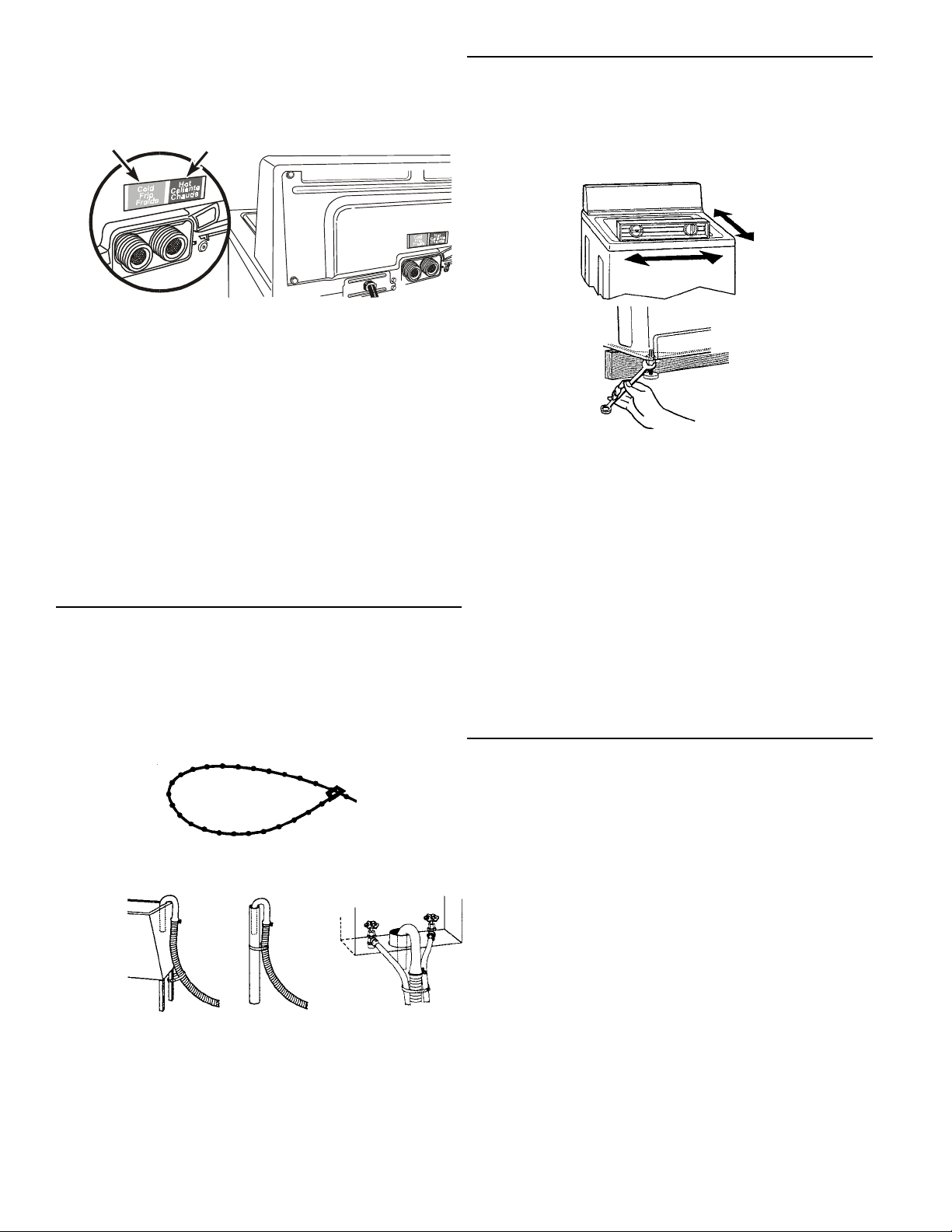
4. Attach the hose with the blue coupling to the COLD (left) inlet
valve. Screw on coupling by hand. Using the pliers, tighten
the coupling an additional two-thirds turn.
NOTE: Do not overtighten. Damage to the valve may result.
1
2
Leveling the Washer
Properly leveling your washer prevents excessive noise and
vibration.
1. Check the levelness of the washer by placing a level on the
top of the washer, first side-to-side, then front-to-back.
Fig. 1-14
1. Cold water inlet valve (blue)
2. Hot water inlet valve (red)
5. Attach the hose with the red coupling to the HOT water (right)
inlet valve. Screw on coupling by hand. Using the pliers,
tighten the coupling an additional two-thirds turn.
NOTE: Do not overtighten. Damage to the valve may result.
Check for leaks
Turn on the water faucets and check for leaks. A small amount of
water might enter the washer. You will drain this later.
Replace inlet hoses after 5 years of use to reduce the risk of hose
failure. Record hose installation or replacement dates for future
reference.
Periodically inspect and replace hoses if bulges, kinks, cuts, wear
or leaks are found.
Fig. 1-1 1
Securing the Drain Hose
1. Remove the power cord from the rear panel of the washer
and drape the cord over the console.
2. Move the washer to its final location and remove any
cardboard used to move washer.
3. Locate the tie strap (supplied).
Fig. 1-12
4. Wrap the drain hose to the laundry tub leg or standpipe with
the tie strap. See illustration.
Fig. 1-13
If the washer faucets and the drain standpipe are recessed,
put the hooked end of the drain hose in the standpipe. Tightly
wrap the tie strap around the water inlet hoses and the drain
hose.
5. Do not force excess drain hose back into the rear of the
washer.
If the washer is not level, prop up the front of the washer and
adjust the feet up or down as necessary. If the washer is
against a wall, move the washer out slightly before tipping
back. Repeat this step until the washer is level.
2. After the washer is in the final location and level, use a 9/16 in.
open-end wrench to turn the nuts on the feet tightly against
the washer cabinet.
If the nuts are not tight against the washer cabinet, the
washer can vibrate.
3. Tilt the washer back and remove the wooden block. Gently
lower the washer to the floor.
4. Move the washer to its final location.
5. Tilt the washer forward until the rear of the washer is at least
4 in. (10.0 cm) off the floor. You may hear the self-adjusting
rear feet click into place. Lower the washer to the floor.
Installation Checklist
1. Check the electrical requirements. Be sure that you have the
correct electrical supply and the recommended grounding.
(See “Electrical Requirements.”)
2. Check to be sure all parts are now installed. If there is an
extra part, go back through the steps to see which step was
skipped.
3. Check to be sure you have all of your tools.
4. Dispose/recycle all packaging materials. Keep the styrofoam
block for repackaging washer for transportation.
5. Check to be sure the water faucets are on.
6. Plug the power supply cord into a grounded outlet.
7. Remove the protective film on the console and any tape
remaining on the washer.
8. Read “Using Your Washer.”
9. Measure ½ the normal recommended amount of powdered
or liquid detergent and pour it into the detergent dispenser.
Close the lid. Press HEAVY DUTY, and then press START.
Allow it to complete one whole cycle.
5

Use & Care Information
Due to the unique washing action of the CALYPSO™ washer, it is strongly recommended that the consumer use
a High Efficiency detergent.
High Efficiency detergents are formulated to control sudsing which may occur with use of regular detergents. If the
consumer does not wish to use HE detergent, it is recommended to use 1/2 the normal amount. In soft water
locations, the quantity may need to be reduced even further.
Only LIQUID chlorine bleach should be used in the Bleach Dispenser. If color-safe bleach, (powder or liquid) is
used, it should be added to the Detergent Dispenser.
This new washer works differently than most washers that you are accustomed to. The most striking difference is
the washer does not have anagitator. It uses the innovative CALYPSO™ Wash Motion. The Wash Plate, at the
bottom of the basket, creates a motion that lifts, rolls and bounces the wash load through a mixture of
water and detergent that is continuously reapplied to the load to force out stains and soils.
The washer uses only enough water to saturate the clothes and recirculate over the load. The water is
filled only to the bottom of the Wash Plate. If the lid is opened during a wash cycle, no water is visible
and no additional water should be added. There is no deep wash/rinse as in traditional washers.
The CALYPSO™ washer spins at much higher speeds, (up to 800 RPM), than traditional washers. To
assist the consumer in unloading the clothing at the end of the cycle, the CAL YPSO™ washer will FLUFF
the load after the spin is completed to loosen the clothing and ease in removal.
6
SECTION TWO
THEORY OF OPERATION
NUTATION
nu-ta-tion \ n(y)ü-’ta-shen\ n The spiral movement of the axis of a rotating body,
such as the oscillation of a spinning top.
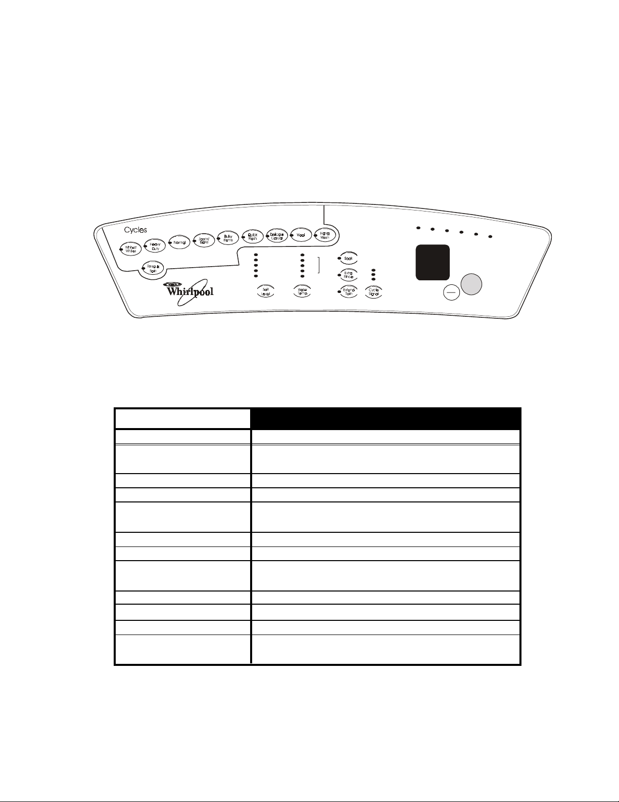
CONTROL PANEL
Sta t u s
So a k
Wa sh
Rinse
Extr a
Sp i n &
Rinse
Cycle
Fluf f
Complete
Options
Extra Heavy
Hea vy
Normal Normal
Light
Refresh
Hot
Cold
Wa rm
Wa rm
Cold
Wa rm
Cold
Cold
Cold
Cold
Fig. 2-1
Assure d
Wa te r
Te m p
L ouder
Softer
Off
Estimated Time
Remainin g
Sto p
Cancel
St a rt
CYCLES
Whitest Whites
Heavy Duty
Normal
Jeans/Darks
Bulky Items
Quick Wash
Delicate/Casual
Wool
Handwash
Rinse & Spin
Extend Spin
CYCLE DESCRIPTIONS
DESCRIPTIONS
For extra whitening (with 1 cup of liquid chlorine
bleach)
For sturdy fabrics and heavy soil
For mixed loads and average soil
For denims and similar colors; prevents white crease
lines in jeans
For large bulky items
For quickly cleaning lightly soiled items
Combination of Delicate and Perm Press/Casual
cycles.
For “hand wash” wool and silk
For garments marked “hand wash” on the care label
Short cycle to rinse out suds & other loose particles
Stand alone high speed drain and spin cycle to
extract water from clothes
7
1234567890123456789
1
9
1
9
1234567890123456789
9
9
9
9
9
9
9
0
0
0
0
0
0
0
0
0
0
0
0
0
0
OPERA TIONAL CYCLE DEF AULT W ASH AND SPIN
0
0
0
0
0
0
MAIN WASH ACTION
CYCLES
Whitest Whites
Heavy Duty
Normal
Jeans/Darks
Bulky Items
Quick Wash
Delicate Casual
Wool
Hand Wash
60 RPM spin and spray wash
60 RPM spin and spray wash
60 RPM spin and spray wash
Rinse & Spin
Extend Spin
NOTE: NPM = Nutations per minute
RPM = Revolutions per minute
OPTION DESCRIPTIONS
275 NPM nutate
300 NPM nutate
275 NPM nutate
250 NPM nutate
250 NPM nutate
250 NPM nutate
N/A-not a wash
N/A-not a wash
FINAL SPIN
800 RPM
800 RPM
800 RPM
800 RPM
400 RPM
800 RPM
400 RPM
300 RPM
400 RPM
800 RPM
800 RPM
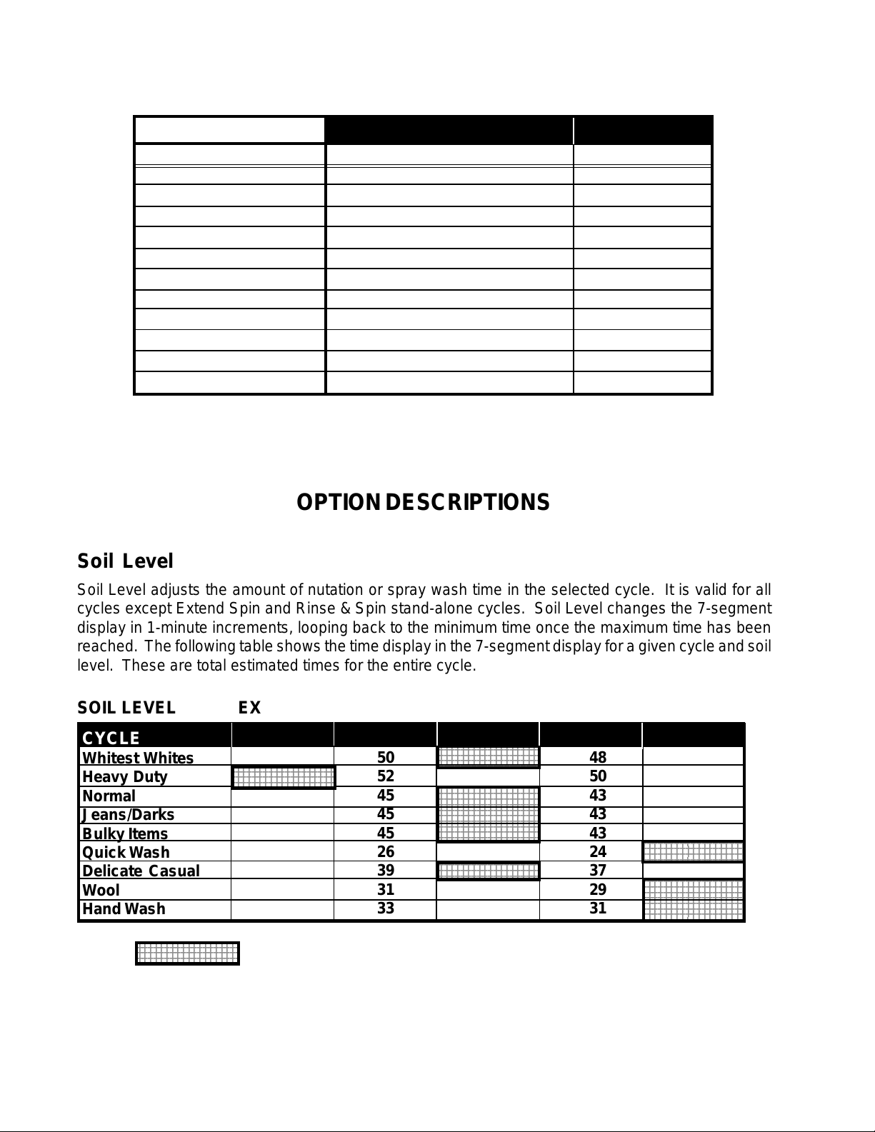
Soil Level
Soil Level adjusts the amount of nutation or spray wash time in the selected cycle. It is valid for all
cycles except Extend Spin and Rinse & Spin stand-alone cycles. Soil Level changes the 7-segment
display in 1-minute increments, looping back to the minimum time once the maximum time has been
reached. The following table shows the time display in the 7-segment display for a given cycle and soil
level. These are total estimated times for the entire cycle.
SOIL LEVEL EX HEAVY HEA VY NORMAL LIGHT REFRESH
CYCLE
Whitest Whites
Heavy Duty
Normal
Jeans/Darks
Bulky Items
Quick Wash
Delicate Casual
Wool
Hand Wash
234567890123456789
234567890123456789
234567890123456789
51
234567890123456789
234567890123456789
234567890123456789
53
46
46
46
27
40
32
34
= Default
50
52
45
45
45
26
39
31
33
234567890123456789
234567890123456789
234567890123456789
49
51
234567890123456789
234567890123456789
44
234567890123456789
234567890123456789
234567890123456789
234567890123456789
44
234567890123456789
234567890123456789
234567890123456789
44
25
234567890123456789
234567890123456789
38
30
32
48
50
43
43
43
24
37
29
31
47
49
42
42
42
23456789012345678
23456789012345678
23
36
23456789012345678
23456789012345678
23456789012345678
28
23456789012345678
23456789012345678
23456789012345678
23456789012345678
30
8
Water Temp
The WATER TEMP keypad provides for selection of different wash and rinse combinations. Water fill
temperatures can be either HOT (hot water valve only), WARM (both the hot and cold water valves) or
COLD (cold water valve only). Fills during rinses may be COLD until the final rinse/spin interval.
The WATER TEMP can be changed at any time during the wash cycle. The action takes place during
a water fill, or the next water fill. Changes late in the cycle are allowed, but may not be acted upon.
SELECTED CYCLE
Whitest Whites
Heavy Duty
Normal
Jeans/Darks
Bulky Items
Quick Wash
Delicate Casual
Wool
Hand Wash
DEFAULT WATER TEMP
Hot/Cold (no ATC)
Warm/Cold (with A TC)
Warm/Cold (with A TC)
Warm/Cold (with A TC)
Warm/Cold (with A TC)
Warm/Cold (with A TC)
Warm/Cold (with A TC)
Cold/Cold (with ATC)
Cold/Cold (with ATC)
Assured Water Temp
The Assured Water Temp LED (if available) lights up whenever the temperature selection is an autocontrolled temp. There are three auto-controlled temperature selections:
• WARM (100°F)/WARM (75°F)
• WARM (100°F)/COLD (“TAP” unregulated)
• COLD (75°F)/COLD (“TAP” unregulated)
There is another WATER TEMP selection that is not auto-controlled (TAP COLD/COLD). Auto temp
control uses the thermistor input as feedback to regulate the hot and cold water valves to achieve the
desired temperature.
ATC Thresholds
AUTO CONTROLLED
Cold Wash/Warm Rinse
Warm Wash
NOTE: ATC controls COLD WASH, WARM RINSE and WARM WASH functions. COLD RINSE is not ATC controlled.
Low Trip
~72° F
56.3K Ω
~89.9° F
37.6K Ω
9
Median
75° F
100° F
High Trip
~80° F
46.3K Ω
~109.9° F
24.2K Ω
THERMISTOR RESISTANCE CHART
THERMISTOR RESISTANCE
Additional Options
OPTIONS
Soak
Extra Rinse
Extend Spin
TEMP
RESIST ANCE VALUE
° F
40
50
60
70
80
90
100
110
120
130
140
150
126k - 135k ohms
97k - 102k ohms
75k - 78k ohms
58k - 61k ohms
46k - 47k ohms
36k - 37k ohms
28k - 30k ohms
23k - 24k ohms
18k - 19k ohms
15k - 16k ohms
12k - 13k ohms
10k - 11k ohms
DESCRIPTIONS
Loosens soils when added to a cycle. Selection of
SOAK will add approximately 16 minutes to the wash
portion of the cycle.
Adds an additional rinse to any cycle.
Adds three, (3), minutes to the final spin time of any
cycle.
End of Cycle Signal
There are three (3) volume levels for the End of Cycle Signal, HIGH, LOW and OFF . Pressing the END
OF CYCLE SIGNAL keypad toggles between these options by lighting one of the LEDs and beeping the
corresponding end of cycle signal at the volume level selected. The LED remains lit during program
mode and running mode until the cycle is complete.
If OFF is selected, no end of cycle signal will beep, but all key and warning beeps are active.
The end of cycle signal is set at a short high pitched, followed by a longer lower pitched tone, repeated
four times.
10
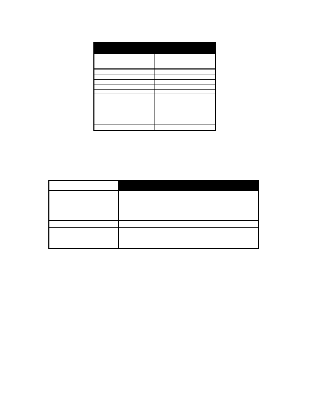
MACHINE CONTROLLER
The Machine Controller interprets the consumer inputs from
the keyswitch pads to operate the cycle selected. The
Machine Controller interfaces with the Motor Controller to
operate the Drive motor and Pump motor through their various functions during the cycle. The Machine Controller
also directly operates the water fill and dispenser solenoids,
interprets the thermistor readings, lid switch condition, as
well as the position of the contacts in the Operating and
Flood Pressure switches.
Fig. 2-2
MOTOR CONTROLLER
The Motor Controller receives commands from the Machine Controller to operate the Drive Motor at the desired
speed and direction at various times in the cycle. It does
so by applying varying voltages and frequencies to the
Drive Motor to control speeds and by electrically leading
with the Main or Aux winding to control direction.
The Motor Controller also operates the Pump Motor direction to either recirculate or drain water.
Fig. 2-3
DRIVE MOTOR
This washer uses a reversible, variable speed SPIM (Single Phase Induction Motor) as its main drive
motor. Motor speed varies from 350 RPM to 4500 RPM. The ½ horsepower motor draws five to seven
amps, in normal use. It uses a voltage output from the motor controller and operates at variable AC
voltages and frequencies. The Motor Controller provides a variable frequency signal to the motor,
which provides the various speeds to nutate and spin. Checking voltages to the drive motor
should not be attempted.
The drive motor has five outputs.
a) Ground
b) FTC- This is 120VAC 60 Hz. and is basically L1.
c) FHOT- This is a combination of 120 VAC 60 Hz, (the return of FTC), and common of the motor,
which is variable frequency and variable voltage.
d) Main- This is one of the windings of the motor. The main winding operates at voltages approximately
170V above and below L1 at a rate of 15K Hz. It uses a variable duty cycle square wave at a voltage
that varies from 30 to 146 V AC referenced to FHOT . The operating frequency varies from 12 to 156 Hz.
The frequency is directly proportional to the speed of the motor. (Higher Frequency = Higher Speed).
In spin, one winding will lead and the other follow. In nutate, the lead winding will be reversed.
e) Auxiliary- See Main winding.
A thermal protector is used to direct voltage to the motor controller instead of acting as a
shut-off for the motor. If the protector is tripped, voltage will be removed from the motor
controller, which in turn, will remove voltage from the drive motor.
11
Peekaboo Mode
The Peekaboo mode allows the user the opportunity to look into the washer during a wash action.
During the Peekaboo Mode, the electronic control will allow the machine to nutate at 150 NPM for a
maximum of 5-seconds after the washer lid is opened. When the lid is closed, the Start pad must be
pressed to continue the cycle.
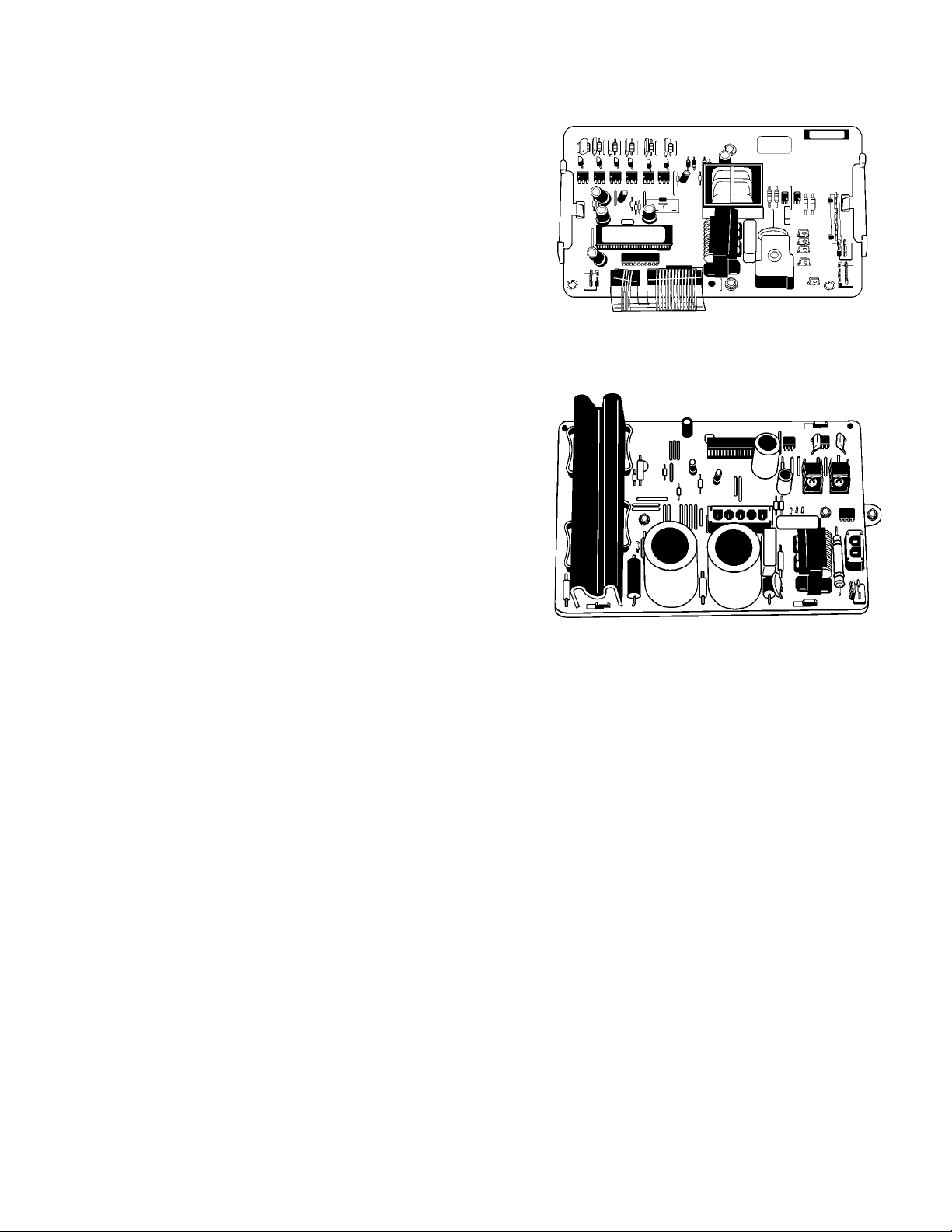
NUT ATION
The Calypso washer achieves a significant energy savings by utilizing less water than a traditional top loading machine with an agitator. This
is made possible by the use of a Wash Plate
which provides an undulating motion to toss the
wash load. This action is called nutation.
The wash plate is tipped at approximately 35 degrees from level. The undulating action constantly
rolls the load over and moving in a circular motion.
The water in the basket is constantly recirculated
and sprayed onto the wash load during wash and
rinse cycles.
Water is Sprayed
on Wash Load
From Here
Wash Plate
Fig. 2-4
Nutate Action
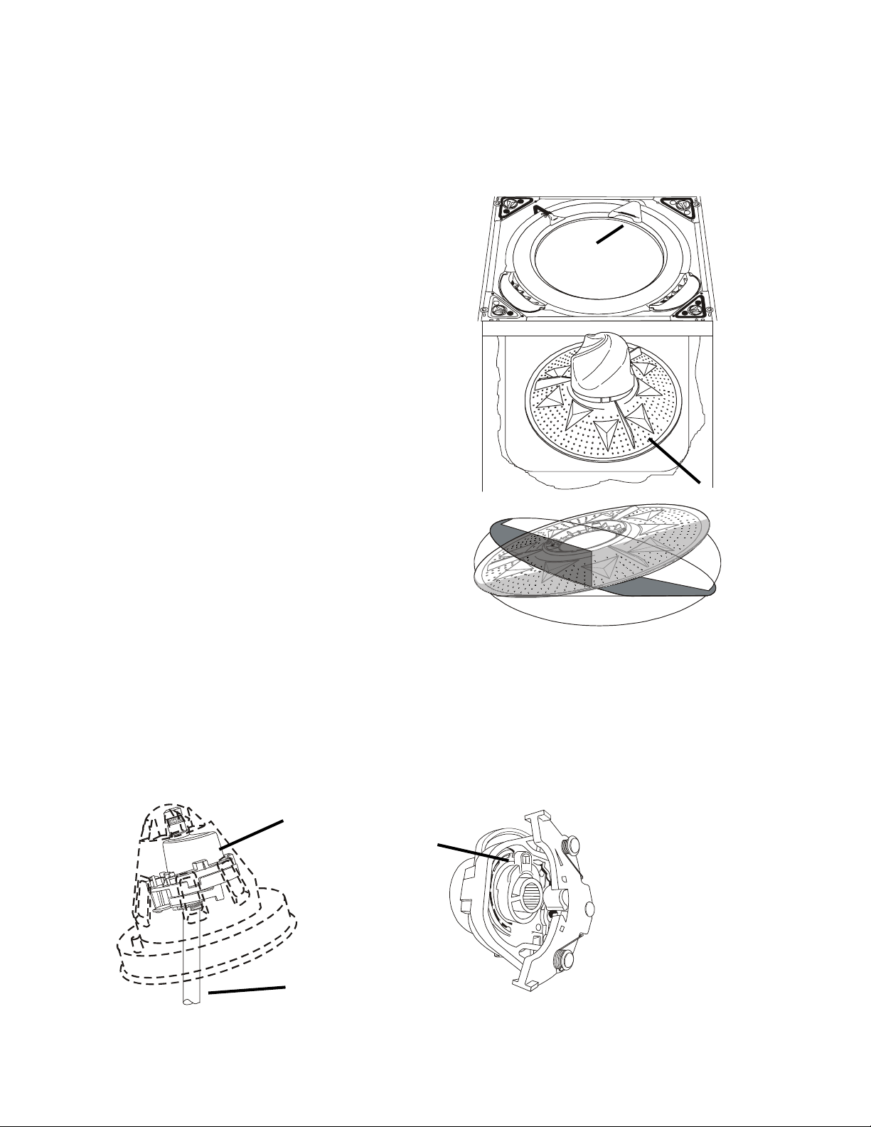
LEVELER
The leveler acts as the mechanism that tilts the nutate or outer wash plate from a level to a 35 degree
tilted position. The leveler is driven by the nutate shaft which replaces the traditional agitator shaft. A
shifting mechanism on the underside of the leveler moves it from a perpendicular alignment in the spin
mode to the 35 degree tilt required for nutation.
Leveler
Note position of
hub tab
Shift Mechanism
(Nutate Position)
Leveler in nutate position.
Nutate Shaft
Fig. 2-5
12
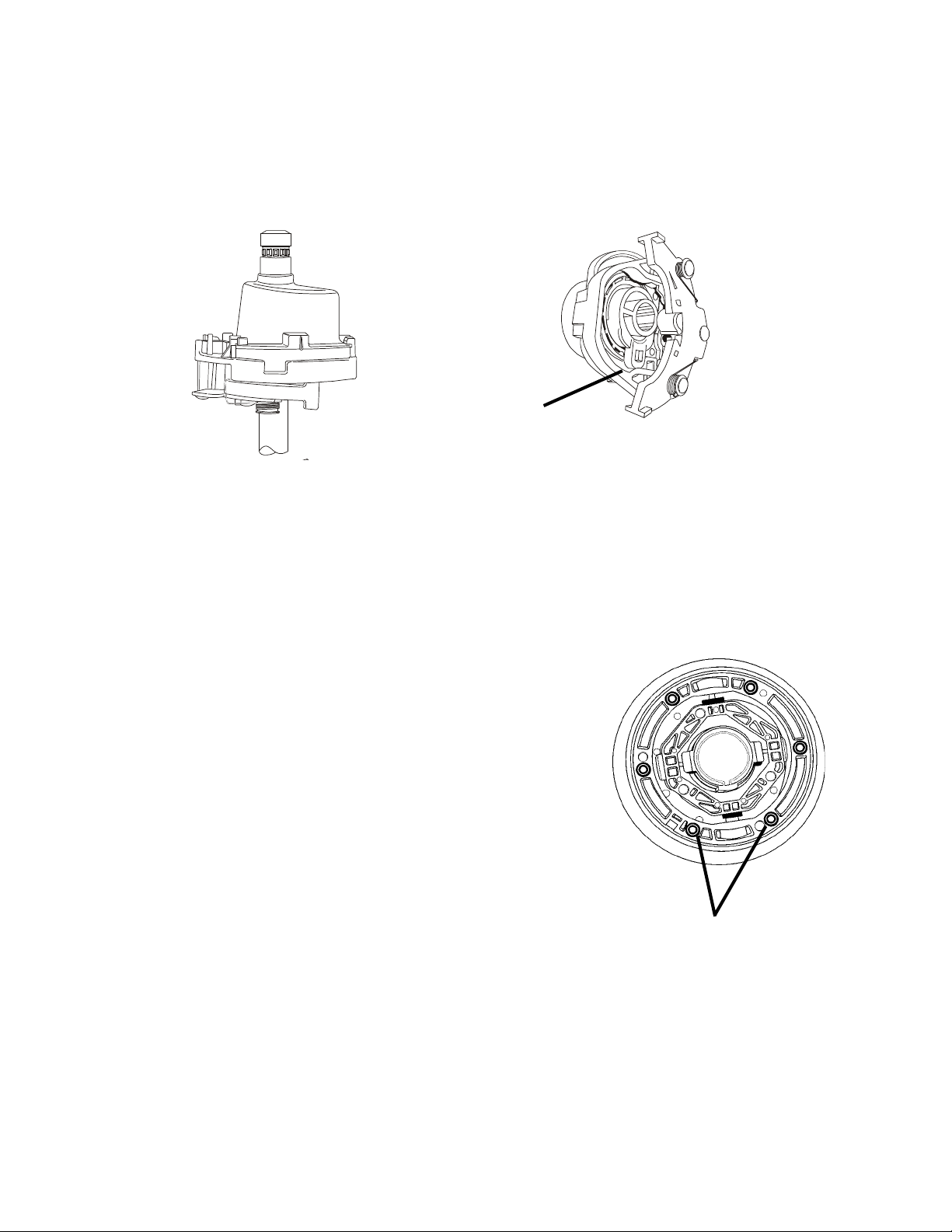
In the spin mode, the top of the leveler is positioned to be in line with the nutate shaft. This levels the
outer wash plate so that the spin basket spins without an out of balance condition that would be caused
by a tilted wash plate.
The leveler shift mechanism is moved from nutate to spin by the nutate shaft direction and an interference with the inner wash plate embossment.
Note position of
hub tab
Shift Mechanism
Leveler in spin position.
(Spin Position)
Fig. 2-6
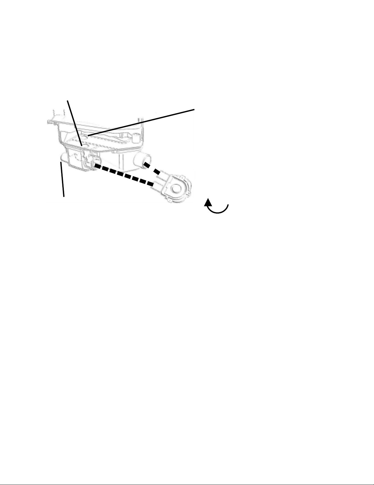
UNIVERSAL JOINT
During Nutation, the Wash Plate is tipped at a 35 degree
angle and must be free to undulate to move the clothing
properly. The Wash Plate is attached to a Universal Joint
that allows the Plate that freedom of movement.
The Universal Joint is attached to the basket drive block by
a spanner nut and is sealed top and bottom by a boot and
various seals to keep water from damaging its pivoting parts.
The boot is attached to the bottom of the U-Joint and prevents water from getting to the U-Joint from underneath. Attached to the basket drive hub is an O-ring that forms a
seal between the U-Joint boot and the basket drive hub.
The top of the U-Joint is sealed by six, (6), grommets and a
gasket that is attached to the underside of the inner wash
plate. The six grommets, wash plate gasket and/or O-ring
MUST be replaced whenever their sealing surface(s) have
been disturbed. The Seal Kit is Part #285842.
U-Joint
grommets
Fig. 2-7
13
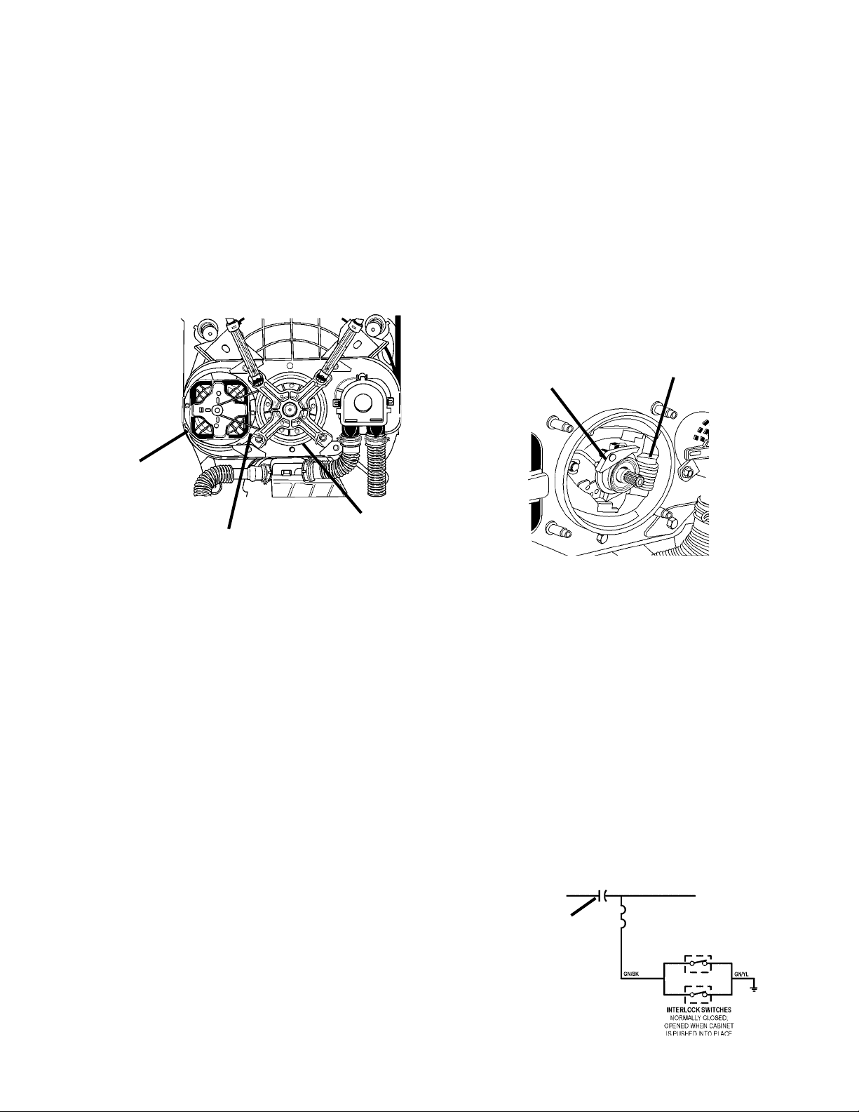
DRIVE SYSTEM
The Drive Motor operates the nutate and spin functions by reversing direction. The Drive Motor is
linked to the drive mechanisms by a stretch belt. The belt transfers the motion of the Drive Motor to a
Drive Pulley. The Drive Pulley has a splined hub, into which the Nutate Shaft is inserted and is in
motion in whichever direction the Drive Pulley is turning. The Drive Pulley , Drive Motor and Drive Belt
all turn in a clock-wise direction, as viewed from underneath when the system is Nutating. The Drive
Motor reverses direction for Spin and causes the Drive Pulley to turn in a counterclockwise direction,
as viewed from underneath. When turning in this direction, an actuating bump in the hub of the Drive
Pulley will contact the Brake Release pawl on the Spin Tube/Brake assembly. This releases the
brakes and allows the basket to spin.
Spin Tube/Brake
Brake Release
Pawl
Drive Motor
Assembly
Drive Pulley
Drive Belt
Fig. 2-8
Fig. 2-9
INTERLOCK SWITCHES
There are two (2) Interlock Switches located behind the front panel and the bottom panel that ground
the drive motor circuit when either panel is removed. When the machine is running with both panels
in place, the drive motor is electrically isolated from ground.
The interlock switches are normally closed and held open when the panels are in place. Removing
either panel grounds the drive motor for safety, but still allows it to operate. This condition may allow
enough current leakage to ground to trip a Ground Fault Interrupter outlet. It is not recommended to
operate the washer with either panel removed. The drive motor can only be tested for continuity in the
field. The drive motor must be disconnected from the electrical source before testing.
Shield Capacitor
A capacitor is in series with the interlock switches and the lower
harness shield to reduce electrical interference created by the drive
motor’s operation. The capacitor is a component of the lower
wiring harness. If the capacitor has failed, the complete lower wiring
harness must be replaced.
Shield
Capacitor
Fig. 2-10
14
PRESSURE SWITCHES
The washer uses two pressure switches to control the amount of water entering the tub and to protect
against an overfill condition. The operating pressure switch, marked OPR, controls the amount of
water that enters the tub during normal wash and rinse functions. This switch operates in the same
manner as similar pressure switches through a pressure switch tube, diaphragm and switch. The
switch contact is normally closed and will open on pressure rise.
The overfill pressure switch, marked FLD, is used to guard against failure of the operating pressure
switch or an overfill condition caused by the consumer adding water to the basket. The overfill pressure switch operates in the same manner as the operating pressure switch, except it’s trip setting is
slightly higher than the operating pressure switch. The switch contact is normally closed and will open
on pressure rise. These pressure switches are NOT interchangeable.
If an overfill condition is detected, the overfill switch will signal the electronic control which causes it to
discontinue the current cycle. “FL” will flash on the control panel display and the beeper will repeat a
warning every 10 seconds. The pump is cycled in drain mode for a half minute on, half minute off until
the overfill switch is reset or power is disconnected from the washer. If the flood switch does reset, the
washer will remain in standby mode with “FL” displayed. It will not automatically restart the cycle.
OPR
FLD
Fig. 2-1 1
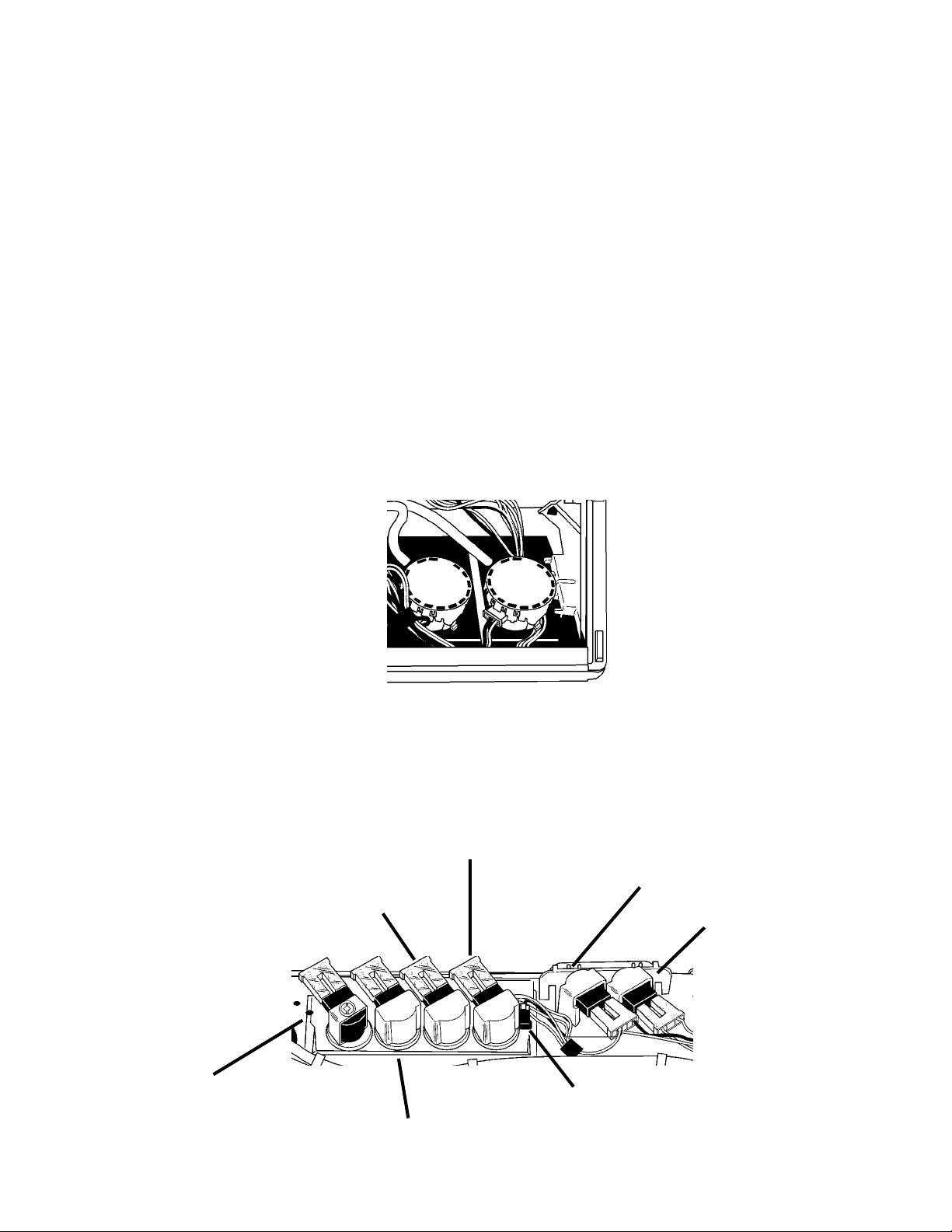
LOG V AL VE ASSEMBL Y
The log valve assembly consists of an inlet valve with hot and cold water valves and solenoids for
incoming water supply and four (4) outlet valves for the water to exit the valve body . The outlets drive
the dispensers under the washer top and allow for fresh water fill. Also included in the log valve
assembly, is the thermistor which is used to monitor incoming water temperature.
Detergent Dispenser Outlet Valve
Hot Water Inlet Valve
Bleach Dispenser Outlet Valve
Cold Water Inlet Valve
Fresh Water Outlet Valve
Fabric Softener Dispenser Outlet Valve
Thermistor
Fig. 2-12
15
RECIRCULATION AND DRAIN
Water Pump/Pump Motor
The pump is directly driven by a separate reversible 120 VAC 60 Hz motor. By being reversible, the
motor provides for two separate operations of the washer.
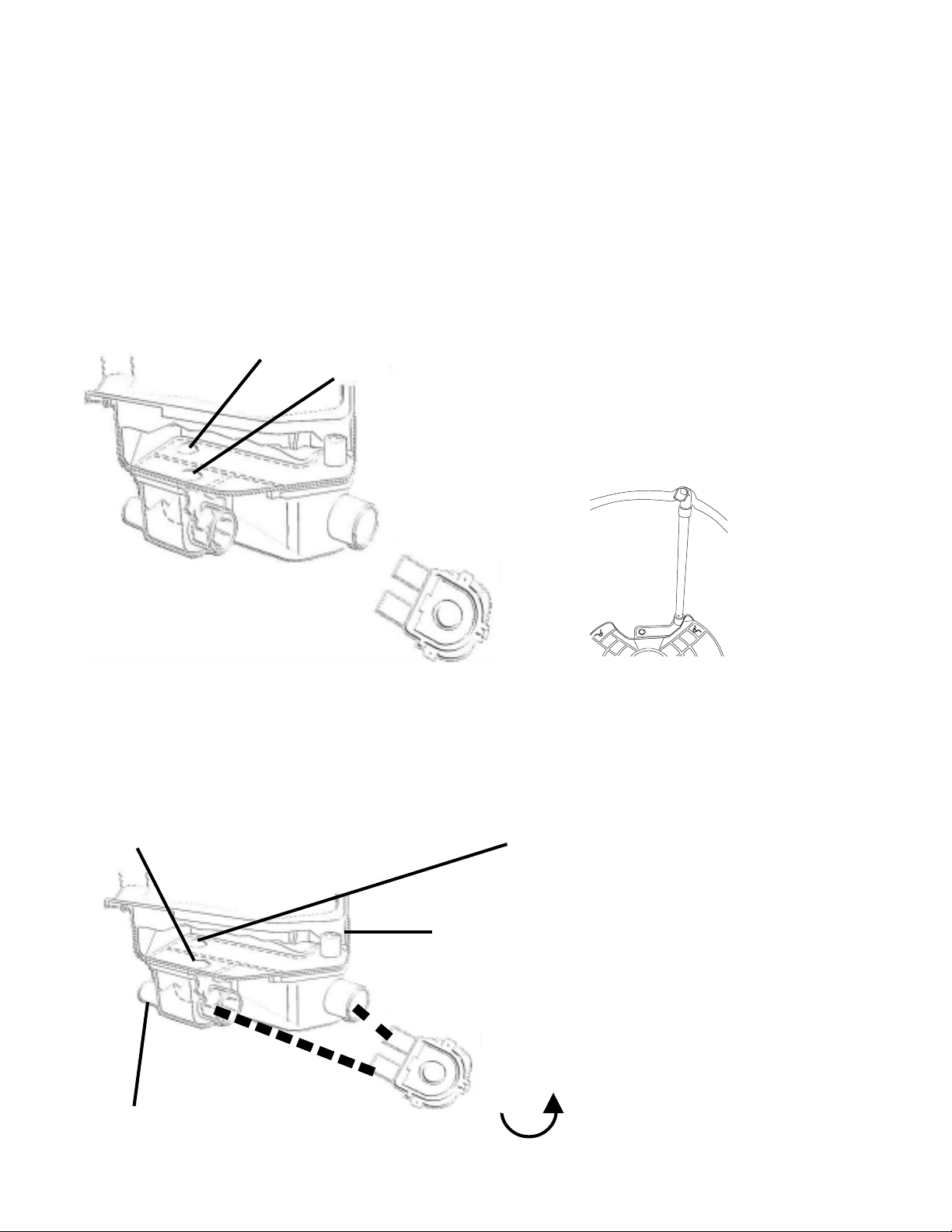
Outer Tub
The Outer Tub sump plays a role in the drain and water recirculation function The sump area includes
two check balls that direct water flow when the water pump operates in the drain and recirc direction.
Recirculation Check Ball
Drain Check Ball
Fig. 2-13
Recirculation
During the Recirculation Mode, the pump motor turns counter-clockwise (as viewed from underneath
the washer). This causes the water pump to draw water from the tub through the drain sump port,
forcing the recirculation check ball to seal the recirculation sump port and force water through the
recirculation tube outlet. Water is recirculated back into the tub onto the load.
When water is present in the tub, the check
balls will float in the proximity of the recirculation and drain sump ports. Water weight or water
pressure applied to the ball(s) will cause them
to drop away from their respective port or seal
off the port.
Recirculation
Tube
Fig. 2-14
Drain Check Ball drops from weight of water
in tub and negative pressure from pump
T o Drain Hose
Recirculation Check Ball seals off the
Recirculation port, due to positive pump
pressure, forcing water to flow out of
Recirculation Feed Tube
Recirculation Feed Tube
Fig. 2-15
Pump Direction
16
Drain
During the Drain Mode, the pump motor turns clockwise (as viewed from underneath the
washer). This causes the water pump to draw the water from the tub through the recirculation port,
forcing the drain check ball to seal the drain sump port and force the water through the drain hose.
Drain Check Ball seals off Drain port, due to
positive pump pressure, forcing water out
the drain hose.
Recirculation Check Ball drops from weight of
water in tub and negative pressure from
pump.
T o Drain Hose
Pump Direction
Fig. 2-16
Changing Cycles and Options
You can change Cycles and Options any time before Start is pressed.
• A short tone sounds when a change is selected.
• Two short tones sound if an unavailable combination is selected. The last selection will not be
accepted.
Changing Cycles after pressing Start
1. Press STOP/CANCEL twice.
2. Select the desired wash cycle.
3. Press START.
The washer restarts at the beginning of the new cycle.
NOTE: If you do not press the Start within 5 minutes of pausing the washer, the washer automatically
shuts off.
Changing Options after pressing Start
You can change an Option anytime before the selected Option begins.
1. Press STOP/CANCEL.
2. Select the new Option.
3. Press START to continue the cycle.
CYCLES
Use the cycle pads to choose the right washer cycle for the type of fabrics you are washing.
• For most loads, use the default soil level recommended in the preset cycle settings.
• For heavy soil and sturdy fabrics, use a higher soil level setting.
• For light soil and delicate fabrics, use a lower soil level setting.
17
 Loading...