

Whirlpool DU1101XTPQ0, DUL240XTPQ0, DUL300XTLB3, DUL300XTLQ3, GU1100XTLB1 Service Pointer
...
REFRIGERATION PRODUCTS KITCHEN PRODUCTSLAUNDRY PRODUCTS
COMMERICAL LAUNDRY
THIS SERVICE POINTER APPLIES TO THE FOLLOWING BRANDS:
33
3
33
K8178505
March 2005
33
3
33
OEM BRANDS
WHIRLPOOL TALL TUB DISHWASHER
Models:
DU1050XTPQ0 DU1101XTPQ0 DU1145XTPQ0
DU1148XTPQ0 DUL240XTPQ0 DUL300XTLB3
DUL300XTLQ3 GU1100XTLB1 GU1100XTLQ1
GU1100XTLS1 GU1100XTLT1 GU1200XTLB3
GU1200XTLQ3 GU1200XTLS3 GU1200XTLT3
GU1500XTLB3 GU1500XTLQ3 GU1500XTLS3
GU1500XTLT3 GU2400XTPQ0 GU2500XTPQ0
GU2548XTPQ0
GU2548XTPQ0GU630XTLQ1
Serial Code date: FR22-FR24
WASH MOTOR REWORK #R14165
CONDITION:
There is a potential overheating condition in the wash pump motor. In rare instances, this condition could cause a fire.
The drain pump motor is not affected and can be reused.
RESOLUTION:
Replace the pump-motor assembly with a motor kit #8194160.
See the attached replacement procedure.
Part Kits should be ordered through Whirlpool authorized parts suppliers.
ALL SERVICE POINTERS ONLINE: http://www.servicematters.com/tech_ref/tech_ref_main.htm, SERVICE POINTERS
COMMERCIAL LAUNDRY ONLY: www.whirlpoolcorp.com/cltpsc, TECHNICAL INFORMATION, SERVICE POINTERS
To receive pointers by email or FAX, or to edit or delete a current email or Fax from our distribution, see
http://www.whirlpoolcorp.com/cltpsc/feedback/feedbacksubscribe_all.html, or FAX changes to 269-923-5342.
WASH MOTOR REPLACEMENT PROCEDURE PROJECT# R14165
UNITS INVOLVED:
Specified Whirlpool brand PLASTIC “TALL TUB” models built with-in serial range specified below:
WHIRLPOOL
FR 22 TO FR 24
CORRECTIVE ACTION:
Open the door and confirm that the dishwasher is a PLASTIC TALL TUB model and falls with-in the specified serial range
above. If the dishwasher meets this criteria, replace the wash motor assembly with part number #8194160.
NOTE: IF the dishwasher was manufactured with a stainless steel tub, is not a plastic tall tub model, or falls outside the
specified serial range above, no further action is necessary.
READ THE BELOW INSTRUCTIONS IN THEIR ENTIRETY BEFORE PROCEEDING.
WARNING
Electrical Shock Hazard
Disconnect power before servicing.
Replace all parts and panels before
operating.
Failure to do so can result in death
or electrical shock.
1. Unplug the dishwasher or disconnect power.
2. Open the dishwasher door and remove the lower dish
rack.
3. Remove the upper dish rack.
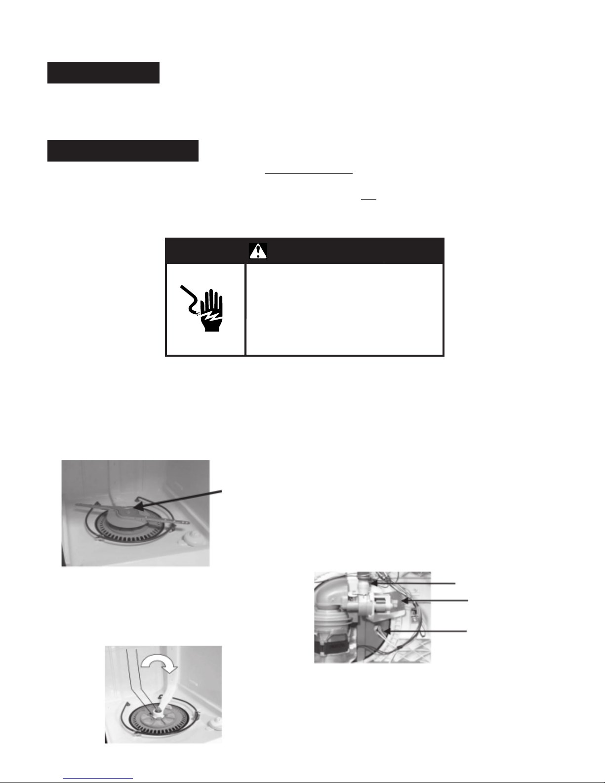
4. Remove the lower spray arm by holding the spray arm
stationary turning the center stud clockwise.
CENTER STUD
5. Remove the upper spray arm water feed tube by first
removing the two screws securing the tube to the
dishwasher tub.
6. Turn the feed tube clockwise to disengage it from the
pump and remove it from the dishwasher.
NOTE: If the dishwasher is not installed under a counter
top in a recessed area and the utilities are disconnected,
lay the dishwasher on it’s back and skip STEP 7.
7. For better access, remove outer door panel by
removing the eight T-15 Torx screws securing the panel
to the inner door.
8. Remove the lower access panel and toe panels.
9. Remove the wiring connectors from the soil sensor
and drain pump.
NOTE: When removing terminals, grasp the terminal
behind the spade connector with a pair of locking pliers so
as not to damage it. The connector can loosen if it is
removed by rocking it. Always pull the connector straight
off.
SOIL SENSOR
DRAIN PUMP
THERMISTOR
10. Remove the thermistor by turning the thermistor one
quarter turn counterclockwise and pulling it out of the
sump.
11. Place a shallow pan or a towel under the soil sensor
to catch any water that may be present in the drain
hose.

12. Remove the T-15 Torx screw securing the soil sensor
and remove the soil sensor. It may be necessary to
remove the drain hose first in order to access the
screw.
REMOVE
SCREW
20. Remove and scrap the old wash motor assembly. To
properly scrap the old motor (prevent it from being
reused), cut the wires going to the harness connector
as illustrated in the picture below. Dispose of the
motor.
13. Take note of the various shields attached to the wash
motor assembly and be sure to return them to their
proper locations during re-assembly.
14. Remove the drain pump by depressing the locking tab
and running the drain pump counterclockwise.
LOCKING
TAB
15. Remove the three sump locking tabs by pulling them
out of the sump.
NOTE: If the dishwasher is on it’s back, set it upright.
SUMP
SUMP
TAB
16. Push upward on the front of the wash-motor assembly
from underneath the sump assembly.
17. Open the dishwasher door.
18. Pull the wash-motor assembly forward slightly and lift
it out of the dishwasher tub.
TAB
PUSH UPWARD ON
THE FRONT OF THE
WASH MOTOR
ASSEMBLY
CUT THESE 3 WIRES
WITH DIAGONAL
CUTTERS
21. Install the NEW wash-motor assembly by first
lubricating the sump gasket with rinse aid.
22. Locate the sump into the tub opening with the locator
tab aligned with the slot in the tub.
LUBRICATE
SUMP SEAL
WITH RINSE AID
LOCATOR
TAB
23. Reverse the procedure to reassemble the dishwasher,
making sure that all the motor shields are reinstalled
properly.
24. Plug in the dishwasher or connect the power.
25. Run a short cycle and check for leaks and for proper
operation.
INSERT
BLUE LABEL
ON
TANK JUST BELOW
MODEL
SERIAL TAG.
19. Disconnect the wash motor wiring connector by
depressing the tabs on either side of the connector
and pull it out of the motor connector.
DEPRESS TABS ON
BOTH SIDES
26. Install Blue label supplied with kit just below the model
/ serial tag on the inside of the tank.
27. Explain the repair procedure to the customer by
covering the content of “leave behind” material included
in kit.
28. Record all customer information, including model,
serial number and the date of purchase for the
dishwasher. Report all this information back to
Whirlpool through the service claim process using
Rework Code #R14165.

BOLETIN DE BOLETIN DE
BOLETIN DE
BOLETIN DE BOLETIN DE
PARA APLICACION INMEDIATA EN SU DEPARTAMENTO DE SERVICIO
SERVICIOSERVICIO
SERVICIO
SERVICIOSERVICIO
PRODUCTOS DE LAVANDERÍA
LAVANDERÍA COMERCIAL
ESTE BOLETIN DE SERVICIO SE APLICA A LAS SIGUIENTES MARCAS
33
3
33
PRODUCTOS DE REFRIGERACIÓN PRODUCTOS DE COCINA
33
3
33
OEM BRANDS
LAVAVAJILLAS DE TINA ALTA
WHIRLPOOL
Modelos
Models:
DU1050XTPQ0 DU1101XTPQ0 DU1145XTPQ0
DU1148XTPQ0 DUL240XTPQ0 DUL300XTLB3
DUL300XTLQ3 GU1100XTLB1 GU1100XTLQ1
GU1100XTLS1 GU1100XTLT1 GU1200XTLB3
GU1200XTLQ3 GU1200XTLS3 GU1200XTLT3
GU1500XTLB3 GU1500XTLQ3 GU1500XTLS3
K8178505
Marzo del 2005
GU1500XTLT3 GU2400XTPQ0 GU2500XTPQ0
GU2548XTPQ0
Fecha de código de serie: FR22-FR24
TRABAJO DE REPARACIÓN DEL MOTOR DE LAVADO #R14165
CONDICIÓN:
Existe una condición potencial de sobrecalentamiento en el motor de la bomba de lavado. En circunstancias excepcionales,
esta condición puede causar un incendio.
El motor de la bomba de desagüe no se ve afectado y puede ser reutilizado.
RESOLUCIÓN:
Reemplace el ensamblaje del motor de la bomba con un juego de motor #8194160.
Vea el procedimiento de reemplazo que se adjunta.
Los juegos de piezas deberán pedirse a través de los distribuidores de
piezas autorizados por Whirlpool.
GU2548XTPQ0GU630XTLQ1
TODOS LOS BOLETINES DE SERVICIO SE ENCUENTRANEN: http://www.servicematters.com/tech_ref/tech_ref_main.htm, SERVICE POINTERS
LAVANDERÍA COMERCIAL UNICAMENTE EN www.whirlpoolcorp.com/cltpsc, INFORMACIÓN TÉCNICA, BOLETINES DE SERVICIO
Para recibirBoletines vía e-mail o FAX, o para editar o borrar un e-mail o Fax desde nuestro centro de distribución, vaya a
http://www.whirlpoolcorp.com/cltpsc/feedback/feedbacksubscribe_all.html, o para cambios de FAX llame al 269-923-5342 .

PROYECTO DE PROCEDIMIENTO DE REEMPLAZO DEL MOTOR DE
LAVADO # R14165
UNIDADES INVOLUCRADAS:
Los modelos de “TINA ALTA” DE PLÁSTICO de las marcas especificadas de Whirlpool fabricados con los números de
serie indicados a continuación:
WHIRLPOOL
FR 22 A FR 24
ACCIÓN CORRECTIVA:
Abra la puerta y confirme que la lavavajillas sea un modelo de TINA ALTA DE PLÁSTICO y que su número de serie
coincida con los indicados anteriormente. Si la lavavajillas cumple con estos criterios, reemplace el ensamblaje del motor
de lavado con el número de parte #8194160.
NOTA: SI la lavavajillas fue fabricada con una tina de acero inoxidable, no es un modelo de tina alta de plástico o no
coincide con el rango de número de serie especificado anteriormente, no se debe tomar ninguna otra medida.
LEA TODAS LAS INSTRUCCIONES SIGUIENTES ANTES DE PROCEDER.
ADVERTENCIA
Peligro de choque eléctrico
Desconecte el suministro de energía
antes de darle servicio.
Vuelva a colocar todas las piezas y
paneles antes de ponerlo a funcionar.
No seguir esta instrucción puede
ocasionar la muerte o choque eléctrico.
1. Desenchufe la lavavajillas o desconecte el suministro
de energía.
2. Abra la puerta de la lavavajillas y saque la canasta de
platos inferior.
3. Retire la canasta de platos superior.
4. Retire el brazo rociador inferior sosteniendo la parte
fija del mismo y girando hacia la derecha el husillo
central.
HUSILLO
CENTRAL
5. Retire el tubo de alimentación de agua del brazo
rociador superior quitando primero los dos tornillos que
aseguran el tubo a la tina de la lavavajillas.
6. Gire el tubo de alimentación hacia la derecha para
desengancharlo de la bomba y sáquelo de la
lavavajillas.
NOTA: Si la lavavajillas no está instalada debajo de un
mostrador en un área empotrada y los servicios están
desconectados, ponga la lavavajillas con su parte posterior
sobre el piso y saltee el PASO 7.
7. Para obtener un mejor acceso, retire el panel de la
puerta quitando los ocho tornillos Torx T-15 que
aseguran el panel exterior a la parte interior de la
puerta.
8. Retire el panel de acceso inferior y los paneles de pie.
9. Retire los conectores de cableado del sensor de
suciedad y de la bomba de desagüe.
NOTA: Cuando saque las terminales, tome la terminal que
está detrás del conector de horquilla con un par de alicates
de traba para no dañar el conector. El conector se puede
aflojar si se lo quita sacudiéndolo. Siempre jale el conector
directamente hacia afuera.
SENSOR DE SUCIEDAD
BOMBA DE DESAGÜE
TERMISTOR
10. Retire el termistor girándolo un cuarto de vuelta hacia
la izquierda y jálelo hacia afuera de la bomba.
11. Coloque una charola poco profunda o una toalla debajo
del sensor de suciedad para recoger el agua que
pudiera haber en la manguera de desagüe.

12. Quite el tornillo Torx T-15 que asegura el sensor de
suciedad y retire el sensor de suciedad. Es posible
que sea necesario quitar la manguera de desagüe
primero para poder acceder al tornillo.
PRESIONE LAS
LENGUETAS EN AMBOS
LADOS
QUITE EL
TORNILLO
13. Fíjese en las varias pantallas que están sujetas al
ensamblaje del motor de lavado y tenga cuidado de
devolverlas a sus ubicaciones adecuadas durante el
ensamblaje.
14. Retire la bomba de desagüe oprimiendo la lengüeta
de sujeción y girando la bomba de desagüe hacia la
izquierda.
LENGÜETA
DE
SUJECIÓN
15. Retire las tres lengüetas de fijación de sumidero
jalándolas fuera de la misma.
NOTA: Si la lavavajillas está recostada sobre su parte
posterior, póngala en posición vertical.
LENGÜETA DE
SUMIDERO
16. Empuje hacia arriba en la parte frontal del ensamblaje
del motor desde la parte inferior del ensamblaje de
sumidero.
17. Abra la puerta de la lavavajillas.
18. Jale el ensamblaje del motor de lavado ligeramente
hacia adelante y levántelo fuera de la tina de la
lavavajillas.
LENGÜETA DE
SUMIDERO
EMPUJE HACIA ARRIBA EN
LA PARTE FRONTAL DEL
ENSAMBLAJE DEL MOTOR
DE LAVADO
20. Quite y deseche el viejo ensamblaje del motor de
lavado. Para desechar adecuadamente el motor viejo
(evitar que sea utilizado nuevamente), corte los cables
que van hacia el conector del arnés como se ilustra a
continuación. Deshágase del motor.
CORTE ESTOS 3 ALAMBRES CON
CORTADORES DIAGONALES
21. Instale el ensamblaje del motor de lavado NUEVO
lubricando primero la empaquetadura de sumidero con
agente de enjuague.
22. Ubique el sumidero en la abertura de la tina con la
lengüeta de ubicación alineada con la ranura en la
tina.
LUBRIQUE EL SELLO DE
SUMIDERO CON AGENTE DE
ENJUAGUE
LENGÜETA DE
UBICACIÓN
23. Invierta el procedimiento para volver a ensamblar la
lavavajillas, asegurándose de que todas las pantallas
del motor estén instaladas nuevamente en forma
adecuada.
24. Enchufe la lavavajillas o conecte el suministro de
energía.
25. Ponga a funcionar un ciclo corto y verifique si hay
fugas y si está funcionando adecuadamente.
INSERTE LA ETIQUETA
AZUL EN EL TANQUE
JUSTO DEBAJO DE LA
ETIQUETA CON LA
SERIE DEL MODELO.
19. Desconecte el conector de cableado del motor de
lavado oprimiendo las lengüetas a ambos lados del
conector y jalándolo fuera del conector del motor.
26. Instale la etiqueta azul provista con el juego debajo
de la etiqueta con el modelo / serie en la parte interior
del tanque.
27. Explique al cliente el procedimiento de reparación;
abarque el contenido del material para “guardar detrás”
incluido en el juego.
28. Anote toda la información para el cliente, incluyendo
el número de modelo, serie y la fecha de compra de
la lavavajillas. Notifique toda esta información a
Whirlpool a través del procedimiento para reclamos
de servicio usando el Código de reparación N° R14165.
 Loading...