


GSF26C5EXY
Whirlpool GSF26C5EXY, GSS26C5XXA, GSS26C5XXB, GSS26C5XXW, GSS26C5XXY Technical Education
...
TECHNICAL EDUCATION
JOB AID W10338921
R-110
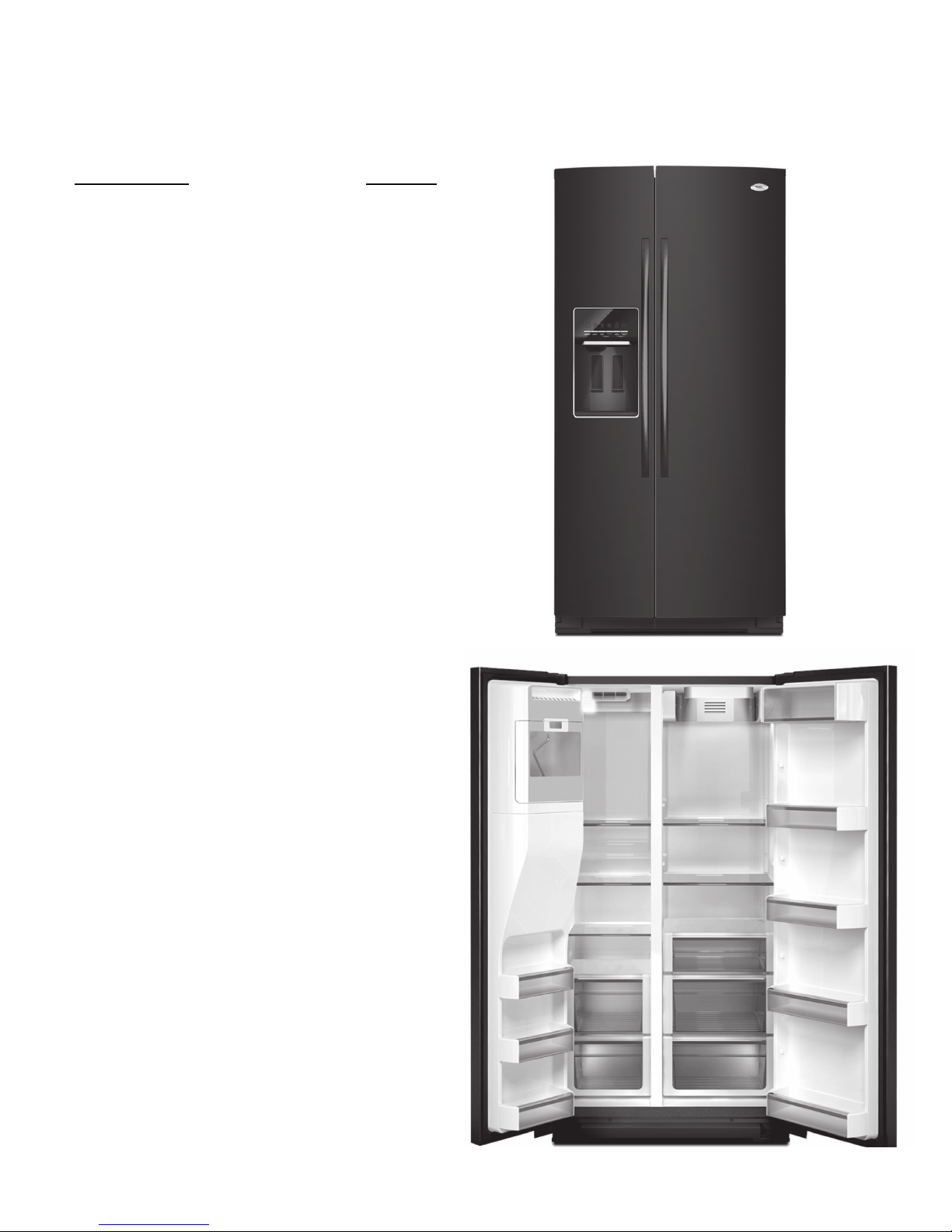
2010 Whirlpool 26’
SXS Refrigerators
GSF26C5EXW
GSF26C5EXY
GSS26C5XXA
GSS26C5XXB
GSS26C5XXW
GSS26C5XXY
GSF26C5EXS
GSF26C5EXT

FORWARD
This Job Aid, Whirlpool Gold 26’ SXS 2010 Part Number W10330404 has been compiled to
provide the recent information on design, features, operation, troubleshooting and repair procedures for 26’ SXS for 2010.
This Job Aid is not intended to replace or substitute for the Use and Care Guides or Tech Sheets
associated with any of the models covered. Refer to the Technical Service sheet shipped with
the refrigerator for detailed information for the unit you are servicing.
GOALS AND OBJECTIVES
The goal of this Job aid is to provide basic information that will enable the service technician to
properly diagnose malfunctions and repair 26” SXS refrigerators for 2010.
The objectives of this Job Aid are to:
• Understand and follow proper safety precautions.
• Successfully troubleshoot and diagnose malfunctions.
• Successfully perform necessary repairs.
• Successfully return the refrigerator to its proper operational status.
Specic components and procedures covered in this Job Aid are:
Grille Removal
Leveling
Door Alignment
Door Removal
Small 6 Cube Ice Maker
Dispenser
Thermistors
Air and Water Filters
Evaporator Fan
Defrost Heater
Defrost Bimetal
Overload Protector
Condenser Fan Motor
Start Module
Stealth Control
WHIRLPOOL CORPORATION assumes no responsibility for any repairs made on
our products by anyone other than authorized In-Home Service Professionals.
Copyright © 2010, Whirlpool Corporation, Benton Harbor, MI 49022
- ii -

TABLE OF CONTENTS
Page
GENERAL . . . . . . . . . . . . . . . . . . . . . . . . . . . . . . . . . . . . . . . . . . . . . . . . . . . . . . . . . . . . . . 1-1
Safety ................................................................ 1-1
Introduction Specifications and Overview . . . . . . . . . . . . . . . . . . . . . . . . . . . . . . . . . . . . 1-2
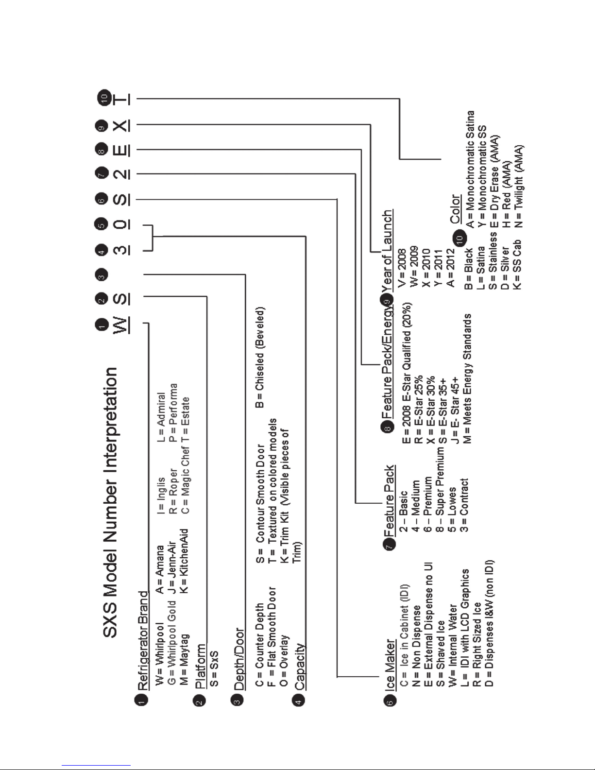
SxS Model Number Interpretation .......................................... 1-3
6th Sense Technology ................................................... 1-4
INSTALLATION REQUIREMENTS . . . . . . . . . . . . . . . . . . . . . . . . . . . . . . . . . . . . . . . . . . . 2-1
Installation Instructions . . . . . . . . . . . . . . . . . . . . . . . . . . . . . . . . . . . . . . . . . . . . . . . 2-1, 2-7
REFRIGERATOR COMPONENTS . . . . . . . . . . . . . . . . . . . . . . . . . . . . . . . . . . . . . . . . . . . 3-1
Disassembling Refrigerator Compartment Components . . . . . . . . . . . . . . . . . . . . . . . . . 3-1
Disassembling Refrigerator Compartment Components –Water Filter Housing . . . . . . . 3-3
Refrigerator Thermistor . . . . . . . . . . . . . . . . . . . . . . . . . . . . . . . . . . . . . . . . . . . . . . . . . . 3-4
Accessing Water Reservoir . . . . . . . . . . . . . . . . . . . . . . . . . . . . . . . . . . . . . . . . . . . . . . . 3-6
FREEZER COMPARTMENT AND ICE MAKER . . . . . . . . . . . . . . . . . . . . . . . . . . . . . . . . . 4-1
Freezer Components .................................................... 4-1
Checking the Freezer Thermistor ........................................... 4-1
Accessing Freezer Components . . . . . . . . . . . . . . . . . . . . . . . . . . . . . . . . . . . . . . . . 4-3, 4-4
Evaporator Component Identification ........................................ 4-4
Removing Evaporator Fan Motor ........................................... 4-5
Checking evaporator Fan motor. . . . . . . . . . . . . . . . . . . . . . . . . . . . . . . . . . . . . . . . . . . . 4-6
Checking Defrost Bimetal. . . . . . . . . . . . . . . . . . . . . . . . . . . . . . . . . . . . . . . . . . . . . . . . . 4-7
Replacing the Defrost Heater .............................................. 4-8
Freezer Door Component Location . . . . . . . . . . . . . . . . . . . . . . . . . . . . . . . . . . . . . . . . . 4-9
Ice maker – Emitter /Receiver Boards ...................................... 4-10
Component Identification ................................................ 4-12
Accessing New In Door Ice Maker ......................................... 4-13
Ice Maker ............................................................ 4-15
Modular Ice Maker & Ice Level Detector Service Sheet. . . . . . . . . . . . . . . . . . . . . . . . . 4-16
Disassembling the Ice Maker. . . . . . . . . . . . . . . . . . . . . . . . . . . . . . . . . . . . . . . . . . . . . 4-17
Replacing Auger Motor and Related Components ............................. 4-19
Removing Auger Motor . . . . . . . . . . . . . . . . . . . . . . . . . . . . . . . . . . . . . . . . . . . . . . . . . 4-20
Checking the Auger Motor . . . . . . . . . . . . . . . . . . . . . . . . . . . . . . . . . . . . . . . . . . . . . . . 4-21
Removing Emitter and Receiver Boards . . . . . . . . . . . . . . . . . . . . . . . . . . . . . . . . . . . . 4-21
Water Tube Routing .................................................... 4-22
DISPENSER AND USER INTERFACE . . . . . . . . . . . . . . . . . . . . . . . . . . . . . . . . . . . . . . . . 5-1
Programming . . . . . . . . . . . . . . . . . . . . . . . . . . . . . . . . . . . . . . . . . . . . . . . . . . . . . . . . . . 5-1
Stealth Control ......................................................... 5-1
Sleep Mode . . . . . . . . . . . . . . . . . . . . . . . . . . . . . . . . . . . . . . . . . . . . . . . . . . . . . . . . . . . 5-2
Adjusting Temperature Set Points . . . . . . . . . . . . . . . . . . . . . . . . . . . . . . . . . . . . . . . . . . 5-4
Adjusting Temperature Settings ............................................ 5-5
Freezer Temperature Setting .............................................. 5-5
Ice Dispenser .......................................................... 5-6
Max Ice. . . . . . . . . . . . . . . . . . . . . . . . . . . . . . . . . . . . . . . . . . . . . . . . . . . . . . . . . . . . . . . 5-7
Dispenser Light . . . . . . . . . . . . . . . . . . . . . . . . . . . . . . . . . . . . . . . . . . . . . . . . . . . . . . . . 5-8
- iii -

TABLE OF CONTENTS (continued)
Door Open Alarm . . . . . . . . . . . . . . . . . . . . . . . . . . . . . . . . . . . . . . . . . . . . . . . . . . . . . . 5-9
Dispenser Lock . . . . . . . . . . . . . . . . . . . . . . . . . . . . . . . . . . . . . . . . . . . . . . . . . . . . . . . 5-10
Cooling Off Mode .......................................................5-11
Cooling On Mode .......................................................5-11
Water Filter Status Light ................................................. 5-12
Showroom Mode . . . . . . . . . . . . . . . . . . . . . . . . . . . . . . . . . . . . . . . . . . . . . . . . . . . . . . 5-13
Accessing User Interface and Dispenser Components . . . . . . . . . . . . . . . . . . . . . 5-14, 5-17
MACHINE COMPARTMENT . . . . . . . . . . . . . . . . . . . . . . . . . . . . . . . . . . . . . . . . . . . . . . . . 6-1
Machine Compartment Components ........................................ 6-1
Starting Device Operation . . . . . . . . . . . . . . . . . . . . . . . . . . . . . . . . . . . . . . . . . . . . . . . . 6-3
Accessing Dual Water Valve . . . . . . . . . . . . . . . . . . . . . . . . . . . . . . . . . . . . . . . . . . . . . . 6-4
Condenser Fan . . . . . . . . . . . . . . . . . . . . . . . . . . . . . . . . . . . . . . . . . . . . . . . . . . . . . . . . 6-5
Drain Pan ............................................................. 6-6
Front Wheel . . . . . . . . . . . . . . . . . . . . . . . . . . . . . . . . . . . . . . . . . . . . . . . . . . . . . . . . . . . 6-7
Control and Power Supply Boards .......................................... 6-8
DIAGNOSTICS, WIRING DIAGRAMS AND TROUBLESHOOTING . . . . . . . . . . . . . . . . . 7-1
Voltage Test Points ...................................................... 7-3
Thermistor Resistance Table .............................................. 7-6
Service Sheet .......................................................7-7, 7-8
Product Specifications And Warranty Information Sources . . . . . . . . . . . . . . . . . . . . . . . 7-4
- iv -
GENERAL
You can be killed or seriously injured if you don't immediately
You
can be killed or seriously injured if you don't
follow
All safety messages will tell you what the potential hazard is, tell you how to reduce the chance of injury, and tell you what can
happen if the instructions are not followed.
Your safety and the safety of others are very important.
We have provided many important safety messages in this manual and on your appliance. Always read and obey all safety
messages.
This is the safety alert symbol.
This symbol alerts you to potential hazards that can kill or hurt you and others.
All safety messages will follow the safety alert symbol and either the word “DANGER” or “WARNING.”
These words mean:
follow instructions.
instructions.
DANGER
WARNING
IMPORTANT SAFETY INSTRUCTIONS
WARNING:
To reduce the risk of fire, electric shock, or injury when using your refrigerator,
follow these basic precautions:
SAVE THESE INSTRUCTIONS
Plug into a grounded 3 prong outlet.
Do not remove ground prong.
Do not use an adapter.
Do not use an extension cord.
Disconnect power before servicing.
Replace all parts and panels before operating.
Remove doors from your old refrigerator.
Use nonflammable cleaner.
Keep flammable materials and vapors,
such as gasoline,
away from refrigerator.
Use two or more people to move and install
refrigerator.
Disconnect power before installing ice maker
(on ice maker
kit ready models only).
Use a sturdy glass when dispensing ice
(on some models).
Safety
Observe all safety warnings and messages.
The Use and Care manual and Installation instructions that come with the product as well as stickers and literature attached to the refrigerator contain safety symbols. These symbols contain messages telling you of potential
hazards and explain how to reduce your chance of injury. The message will also tell you what can happen if the
instructions are not followed.
1-1
Introduction Specications and Overview
Dimensions Inches.
Capacity 26.360
Carton Depth 35
Carton Height 71 1/4
Carton Width 38
Cutout Depth (in) 29 13/16
Cutout Height (in) 69 5/16
Cutout Width (in) 36 1/16
Depth 36
Height 69 1/4
Width 35 7/16
Depth Closed Excluding
Handles
33 1/2
Depth Closed Including
Handles
36
Depth Excluding Doors 29 3/8
Depth With Door Open 90
Degree
50 7/8
Gross Weight 298
Height To Top Of Cabinet 68 5/8
Height To Top Of Door
Hinge
68 15/16
Height To Top of Door Trim 69 1/4
Width Doors Open 90
Degrees
37 3/4
Width of Cabinet Only 35 7/16
Width with Doors Closed 35 3/4
Dimensions Inches.
26’ Dimensions
Capacity 26.360 C.F.
Gross Weight 298 LBS.
1-2
1-3

Introduction Specications and Overview (continued)
6th Sense Technology
th
6
Sense software makes an estimation of
the actual food temperature inside the refrigerator and freezer compartment and adjusts
cooling to allow the food packages to return
their initial temperature faster during pull
th
down, door openings, or heavy food load. 6
Sense algorithm runs in both freezer compartment and refrigerator compartment and
each contains 3 routines: Trigger, Package
Estimator, and Defrost Manager.
Trigger routine is executed every 2.5 seconds while Package Estimator and Defrost Manager
are executed every 10 seconds. The trigger routine is divided into two subroutines: door monitoring and temperature monitoring. Trigger parameters and performance parameters reside in
th
the User Interface board, the actual 6
sense algorithm resides in Gemini Flash board.
Package Estimator routine computes an estimation of food in FC and RC according to Thermistor reading and door status. Package estimator is run when the User Interface sends the
required parameters to Gemini flash and sets the 6th Sense Enable bit to true. If 6
needed, it will call for additional cooling by turning on compressor, damper and evaporator fan.
th
Sense is
Defrost manager is composed of two main states: Normal and 6th Sense.
th
When 6
Sense routine is active, defrost will be inhibited based on the control parameters set-
tings to allow food temperature recovery.
1-4
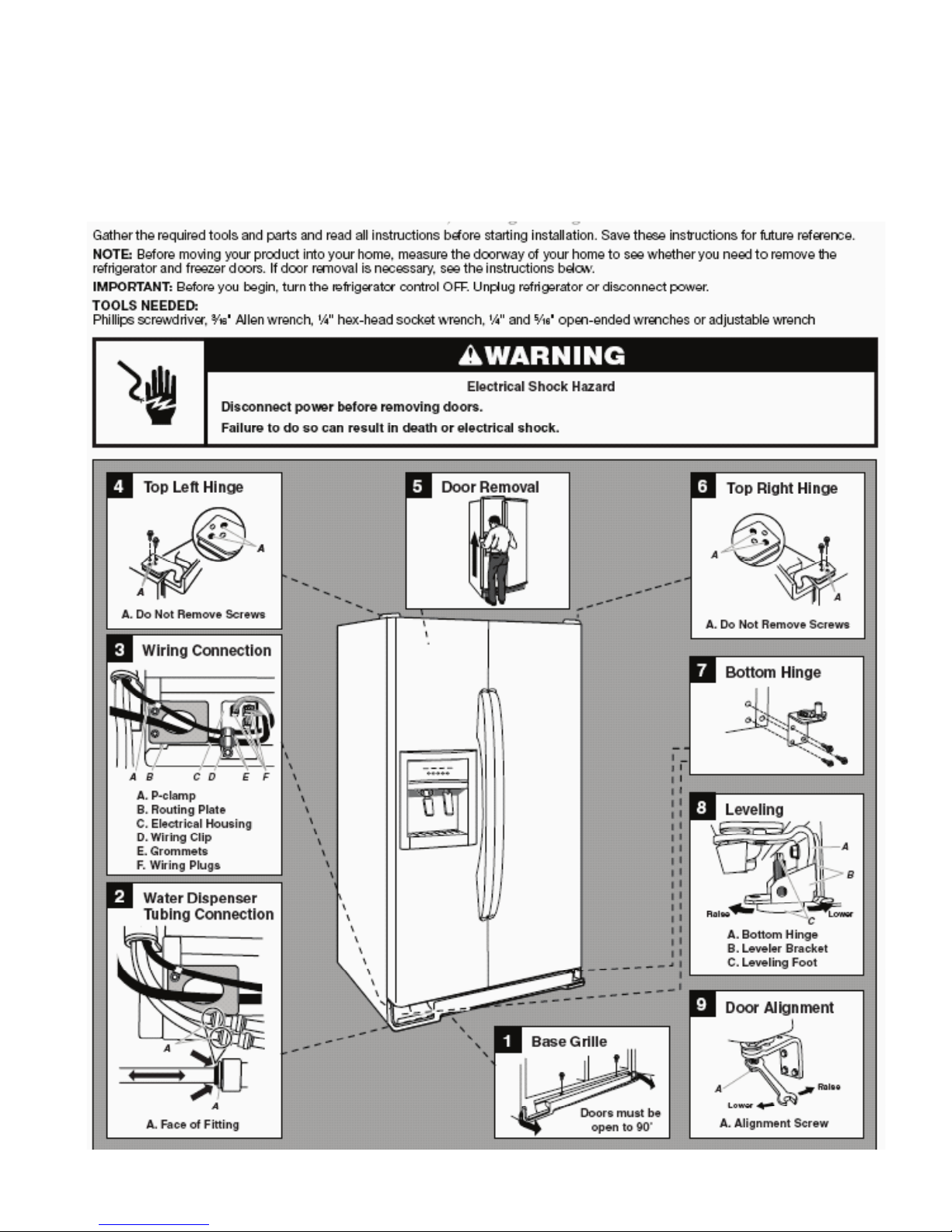
INSTALLATION REQUIREMENTS
Installation Instructions
This new SXS platform requires different installation steps and adjustments than current SXS refrigerators. Review the
Use and Care manual and instruction sheets shipped with the product prior to installation. See the following examples:
Door Removal, Leveling and Alignment
hex
2-1
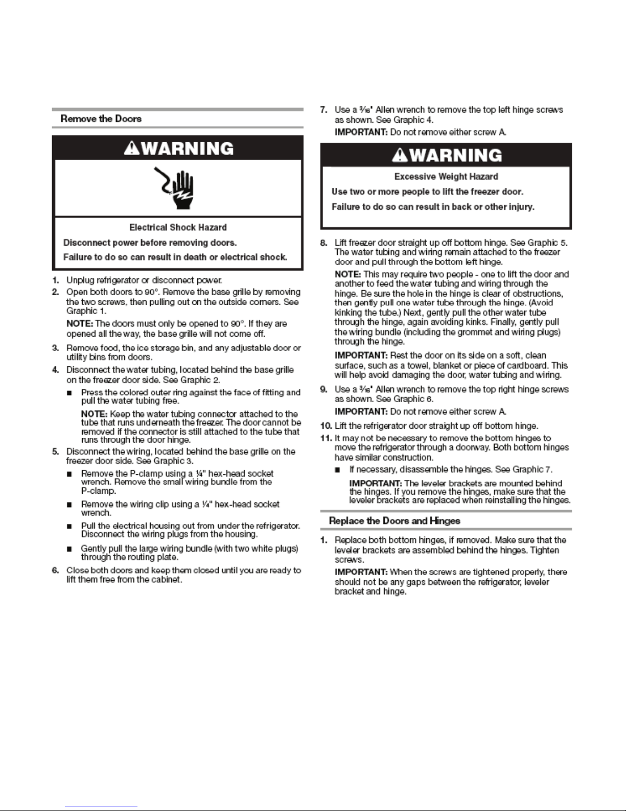
Installation Instructions (continued)
Installation - Example
hex
2-2
Installation Instructions (continued)
Installation - Example (continued)
2-3
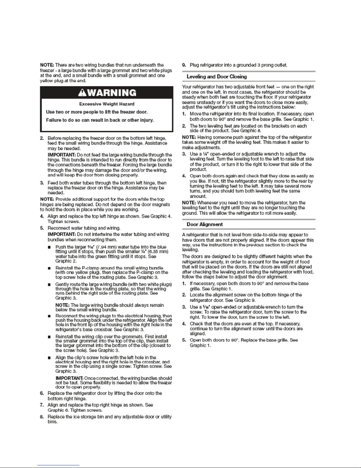
Installation
Refrigerators are shipped with the handles
packed in the refrigerator door.
1. Remove the handles from the door and
unwrap.
2. The instruction sheet and a Hex key tool
are attached to the handle. Review the
1
instruction sheet.
3. Install the handle on the mounting studs
with the hex screws facing to the center.
2
3
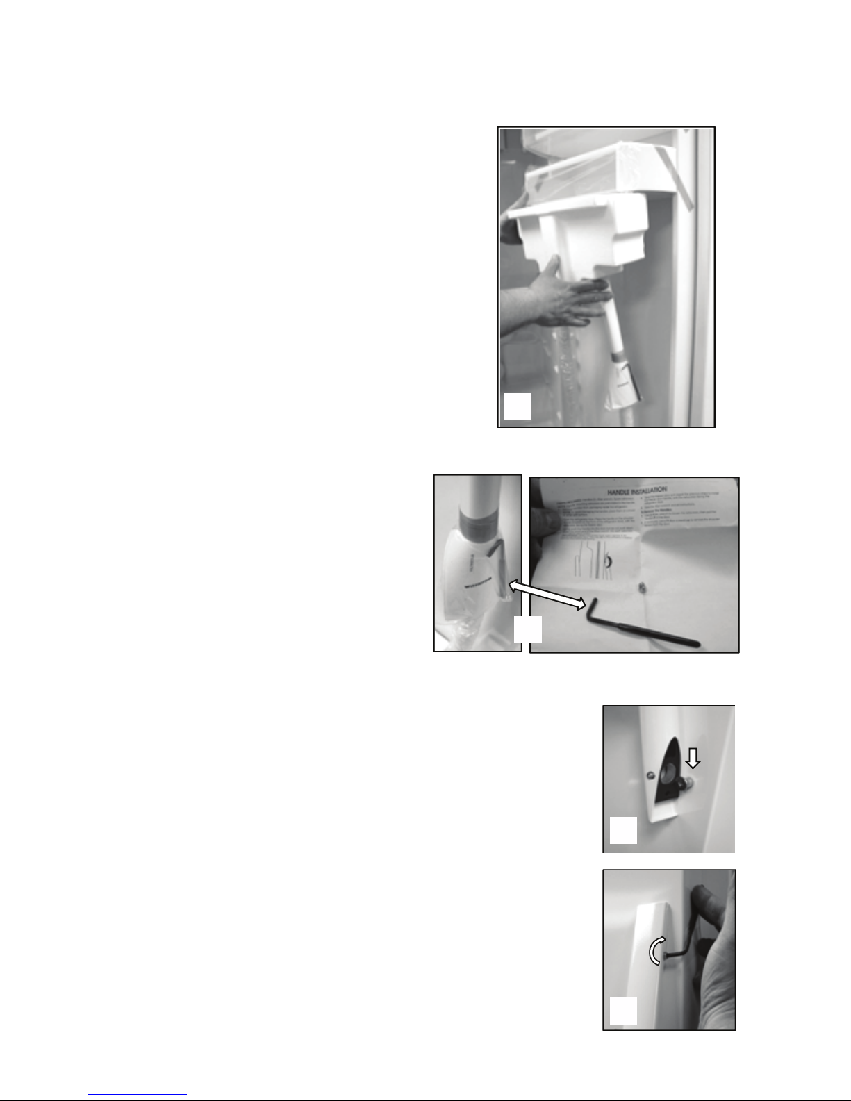
4. Hold the handle tight against the door as
you tighten the screws. The handle will
pull in tight against the door as the screw
is tightened.
4
2-4
Installation Instructions (continued)
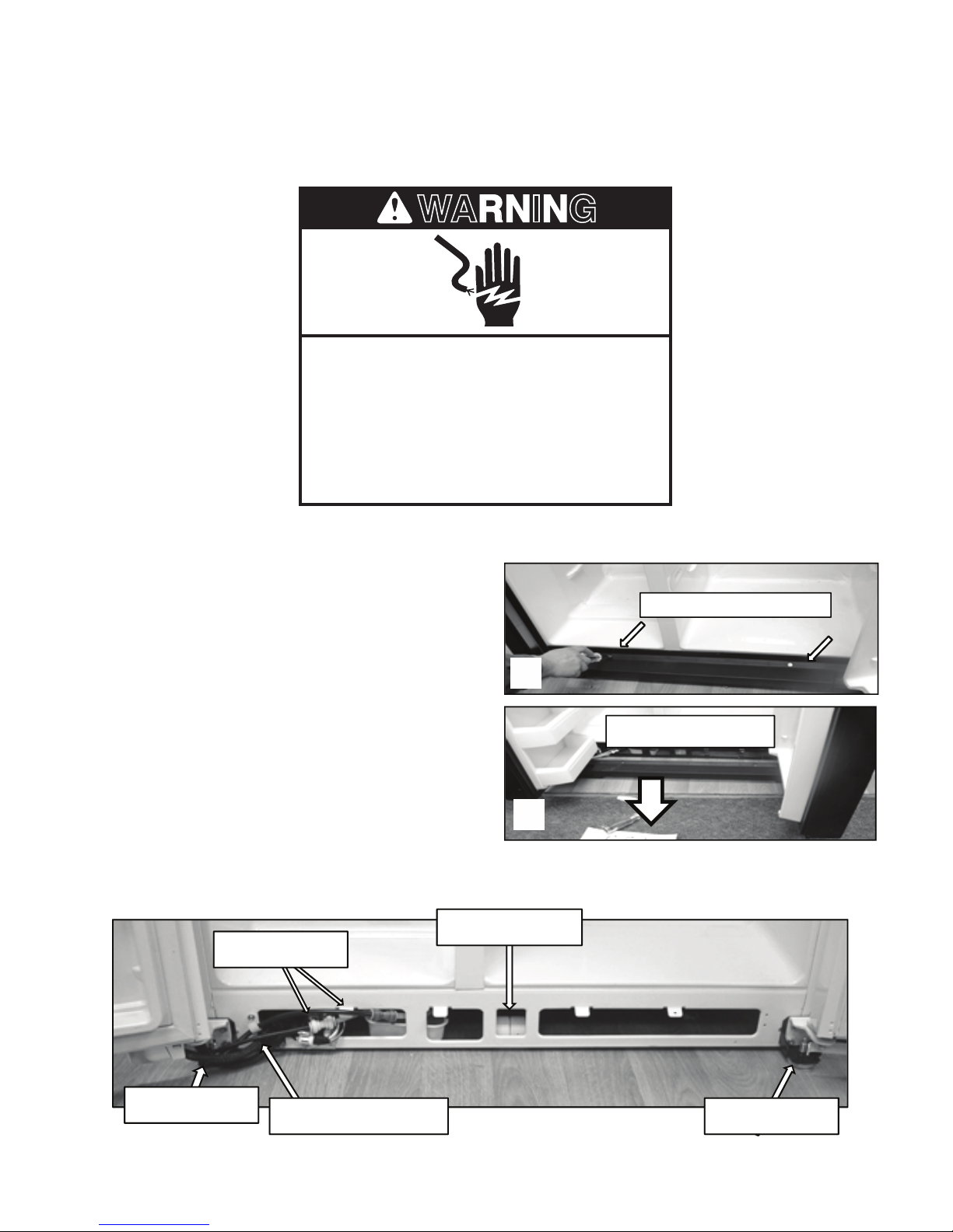
Remove 2 ¼” screws
Remove grille
Center Roller
Wiring Harnesses
Leveler Leg
Leveler Leg
Water Tubes
WARNING
Installation (continued)
Removing Grille
Electrical Shock Hazard
Disconnect power before servicing.
Replace all parts and panels before
operating.
Failure to do so can result in death or
electrical shock.
1. Disconnect power to the refrigerator.
The grille is held in place with 2 ¼” screws.
2. Remove screws
3. Open the doors 90 degrees perpendicular
to the cabinet to remove the grille.
Components Located Behind Grille
2
3
2-5
3
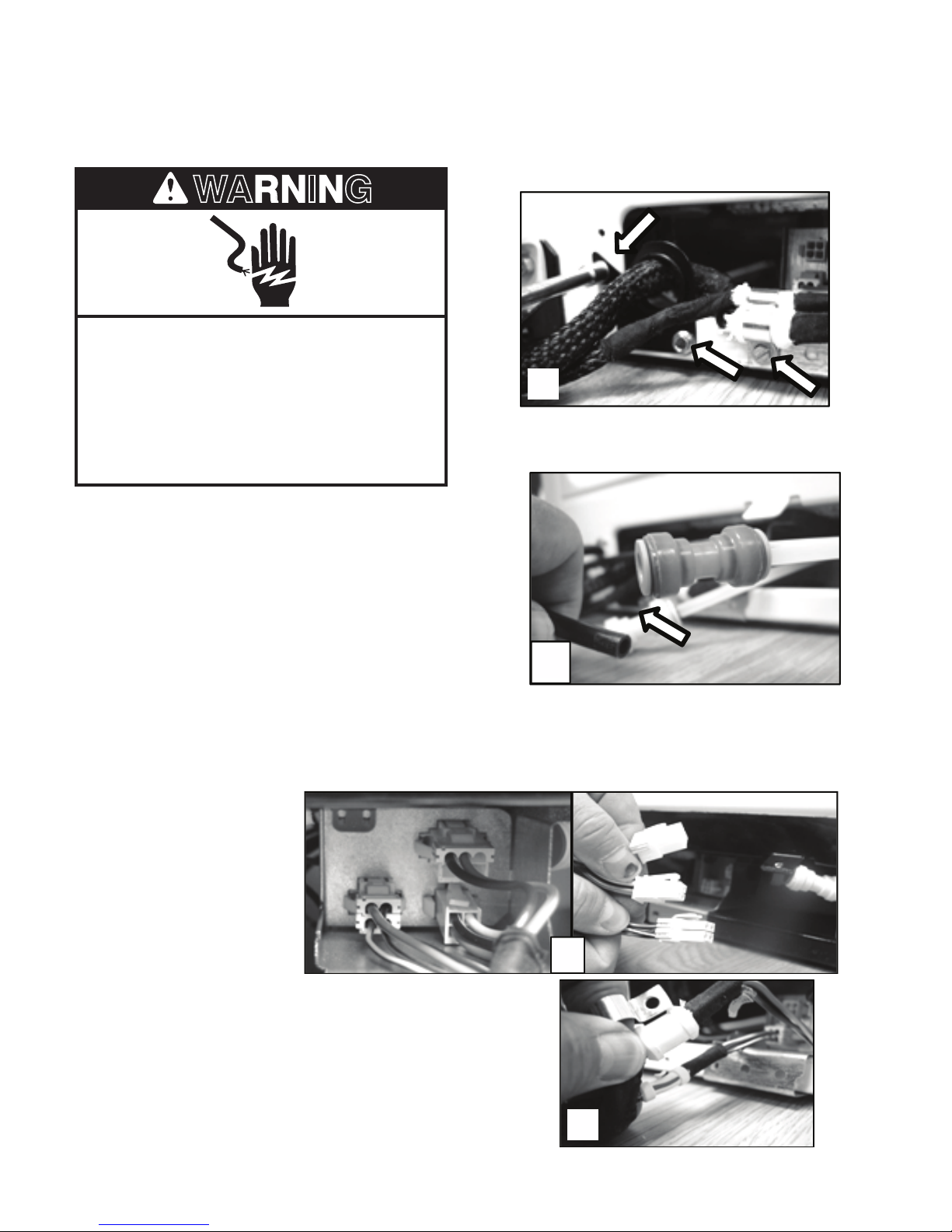
WARNING
Installation Instructions (continued)
2
Removing Freezer Door
Electrical Shock Hazard
Disconnect power before servicing.
Replace all parts and panels before
operating.
Failure to do so can result in death or
electrical shock.
1. Unplug or disconnect the refrigerator from
the power supply.
2
2. Remove the screws securing the wire
harnesses to the cabinet.
3. Disconnect water tubes form the door side
of the connector.
4. Unplug the three
wire harnesses
plugged into the
terminal board.
5. Remove strain relief from the wire harness.
This will allow the harness to pass through
the hole in the hinge.
3
4
5
2-6
Installation Instructions (continued)
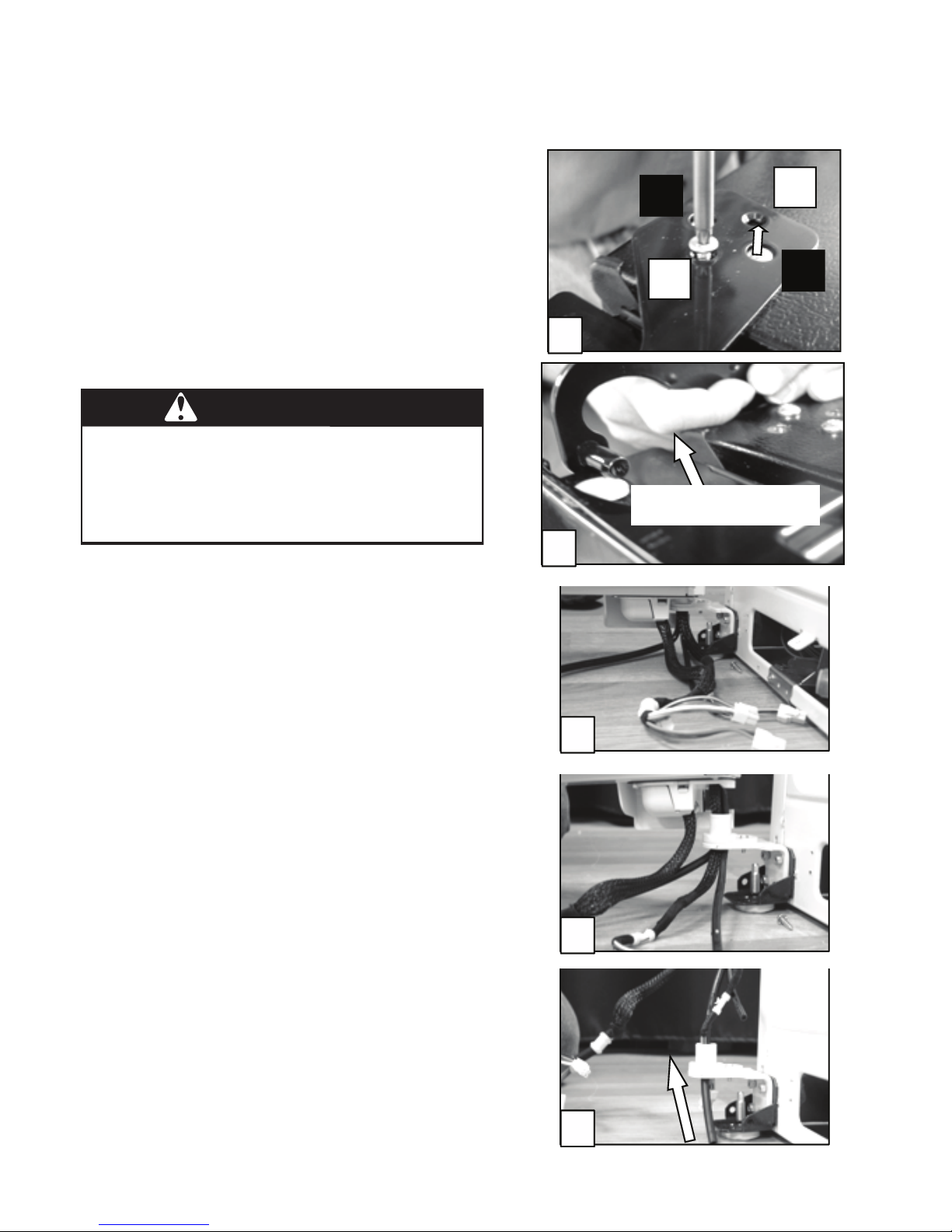
WARNING
Excessive Weight Hazard
Use two or more people to lift the freezer
door.
Failure to do so can result in back or
other injury.
A
B
A
B
5
Lift off the hinge
6
7
8
9
Removing Freezer Door Upper Hinge
6. Remove Two 3/16” hex key screws (A).
Do not remove or loosen the other
two screws (B).
7. Keep the door closed and lift off the
hinge.
6
7
8. Have another person open the freezer
door and lift up slowly.
9. As the door is lifted guide the wiring
harnesses and water tubes through the
hinge.
10. Lift the door straight up to prevent
damage and kinking of the water tube.
8
9
Note: When assembling, always use 2
people and make sure not to crimp the water
tubes when installing through the hinge hole.
10
2-7

—NOTES—
2-8
REFRIGERATOR COMPONENTS
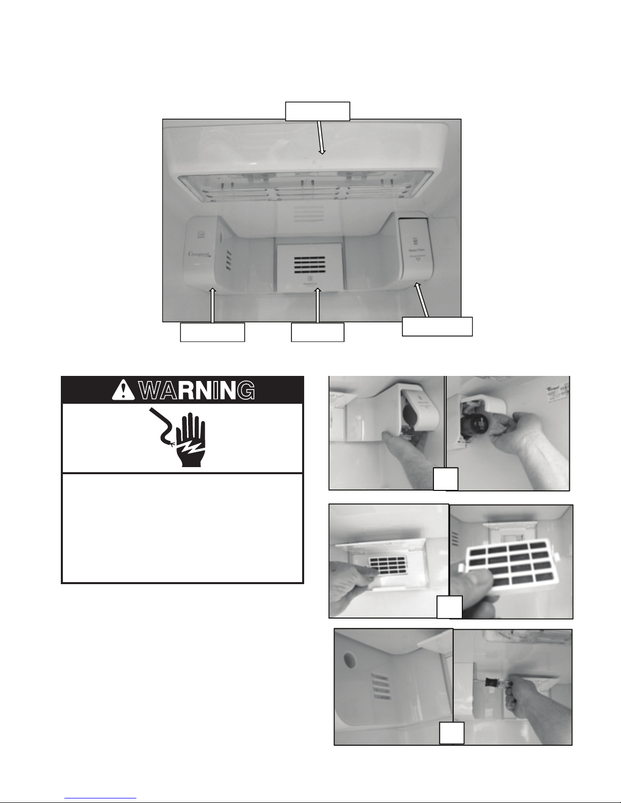
Air Damper Air Filter
Water Filter
Light Bulbs
WARNING
1
2
3
Refrigerator Compartment
Disassembling Refrigerator Compartment Components
Electrical Shock Hazard
Disconnect power before servicing.
Replace all parts and panels before
operating.
Failure to do so can result in death or
electrical shock.
1. Disconnect power to the refrigerator.
2. Open the water lter door and remove the
lter.
3. Open the air lter door and remove the
lter.
4. Remove the ¼” screw securing the air
damper cover to the cabinet.
2
3
4
3-1
Refrigerator Compartment (continued)
6
7
1
2
3
4
5
5. Remove the air damper cover.
6. Remove the ¼” screw securing the air
lter housing to the cabinet and remove.
5
6
7. Disconnect the wiring harness
and remove the air damper
assembly.
8. Check the seal around the damper
housing for any damage or misplace
ment. Replace or reposition seal as
needed.
7
8
3-2
Refrigerator Compartment (continued)
1
2
3
4
Disassembling Refrigerator
Compartment Components –
Water Filter Housing
Remove the water lter as explained earlier.
1. Remove the ¼” screw securing the lter
cover to the lter body.
2. Remove the cover.
3. Remove the ¼” screw securing the lter
body to the cabinet wall.
4. To replace the lter housing, disconnect
the water tubes in the back of the
refrigerator and remove Permagum
seal. Pull the lter housing and water
tubes through the opening in the cabinet
and replace.
3-3
Refrigerator Compartment (continued)
WARNING
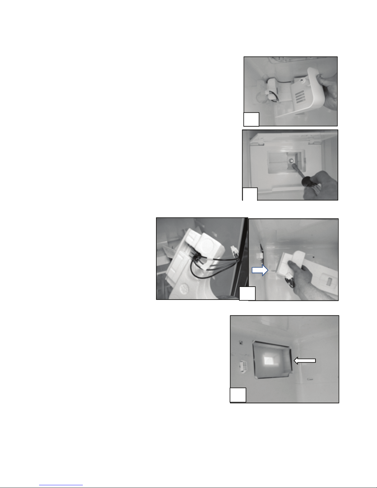
Refrigerator Thermistor
The refrigerator Thermistor is a variable resistance device connected to the control board.
The temperature of the refrigerator compartment causes the resistance of the Thermistor to
change. The resistance is monitored by a circuit on the control board which controls the operation of the cooling system. The Thermistor is located on the right side of the refrigerator cabinet
th
attached to the back of the cover labeled 6
sense.
Refrigerator Thermistor
Electrical Shock Hazard
Disconnect power before servicing.
Replace all parts and panels before
operating.
Failure to do so can result in death or
electrical shock.
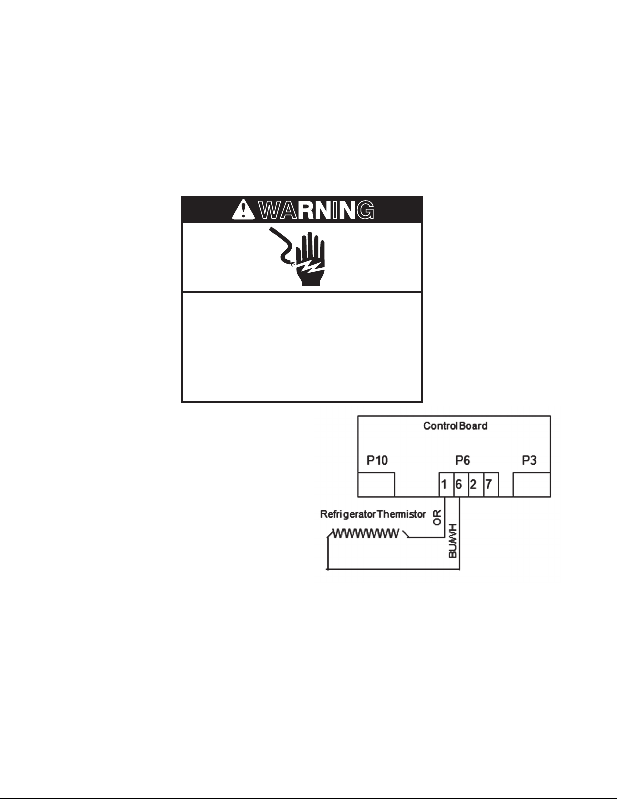
1. Disconnect power to the refrigerator.
2. Disconnect the wiring harness from
connector P6 on the control board.
3. Connect an Ohmmeter across the Orange
and Blue/White wires in the disconnected
wiring harness and measure the
resistance.
4. Compare the resistance measured to the
value listed on the tech sheet shipped
with the refrigerator. Replace Thermistor
if needed.
3-4
1
2
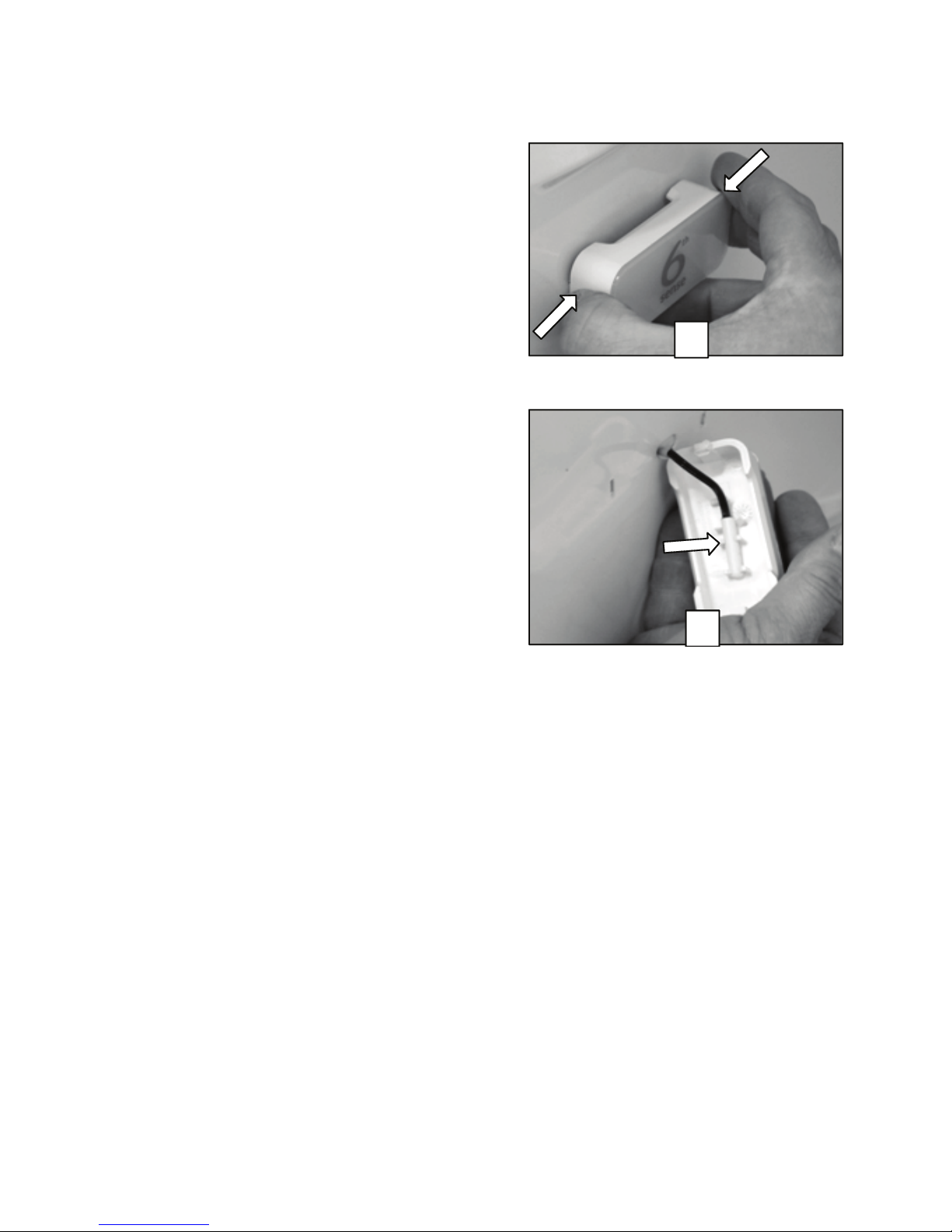
Refrigerator Compartment (continued)
Replacing Refrigerator Thermistor
1. Depress the tabs on either end of the
Thermistor cover and remove.
2. To replace the Thermistor order replace
ment Thermistor kit through the normal
part ordering system by model number.
Follow the instructions supplied with the
kit.
3-5
1
2
3
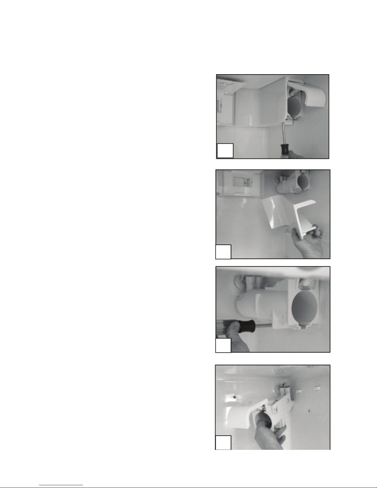
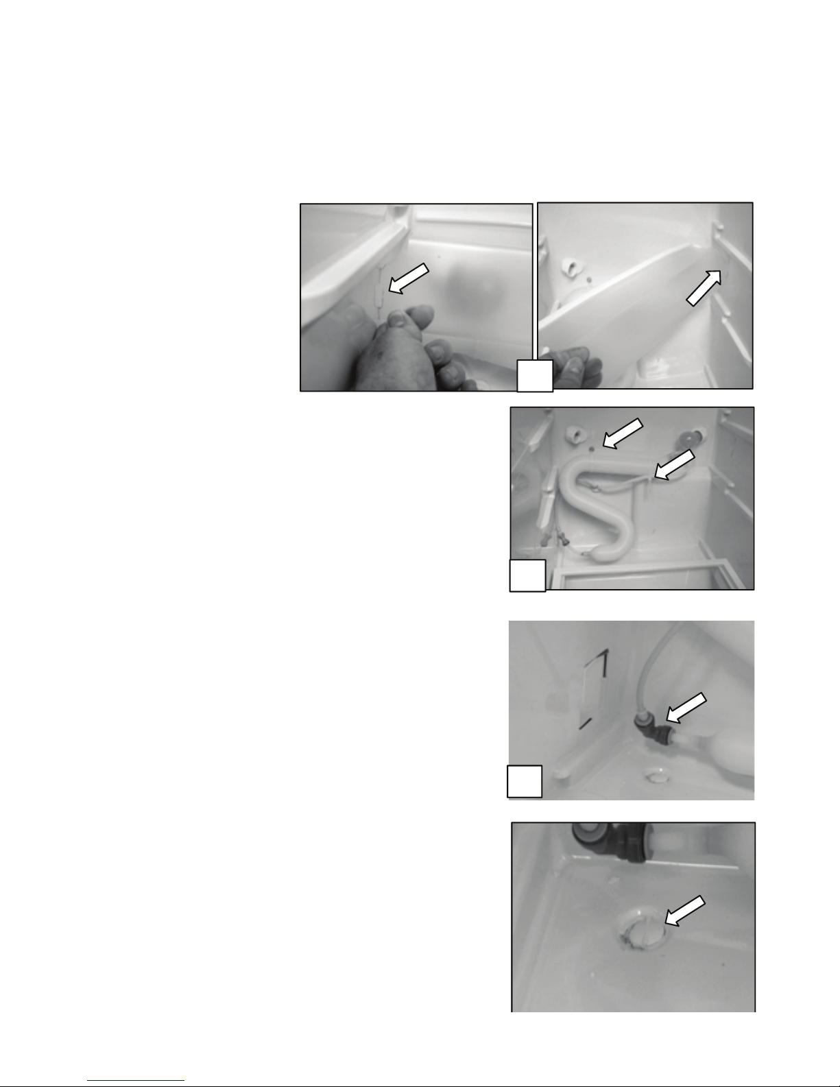
Refrigerator Compartment (continued)
Disassembling Refrigerator Compartment Components – Accessing Water
Reservoir
Disassembling Refrigerator Compartment Components – Accessing Water Reservoir
1. The light bulb cover is very
exible and can be bent to
release the 4 tabs that
extend into the cabinet wall
and remove.
2. To replace the water reservoir, Shut off
water supply.
3. Remove the ¼” hex head screw and the
wire ties securing the reservoir to the
cabinet.
4. Disconnect the water tube connected to
the dual water valve located in the
machine compartment and disconnect the
water tube tting on the lower left
hand corner of the reservoir. Pull out the
water reservoir and the water tube routed
through the opening in the cabinet.
Replace the reservoir.
A vacuum relief is located below the water
reservoir. The purpose of the relief is to allow
pressure to equalize between the inside and
outside of the refrigerator.
3
4
3-6
FREEZER COMPARTMENT AND ICE MAKER
Te mp F
Resistance
Te mp F
Resistance
-10
31402
50
5348
-5
26704
55
4687
0
22774
60
4117
5
19476
65
3624
10
16701
70
3197
15
14359
75
2826
20
12378
80
2503
25
10698
85
2221
30
9268
90
1974
40
7007
95
1758
45
6115
100
1569
WARNING
Freezer Components
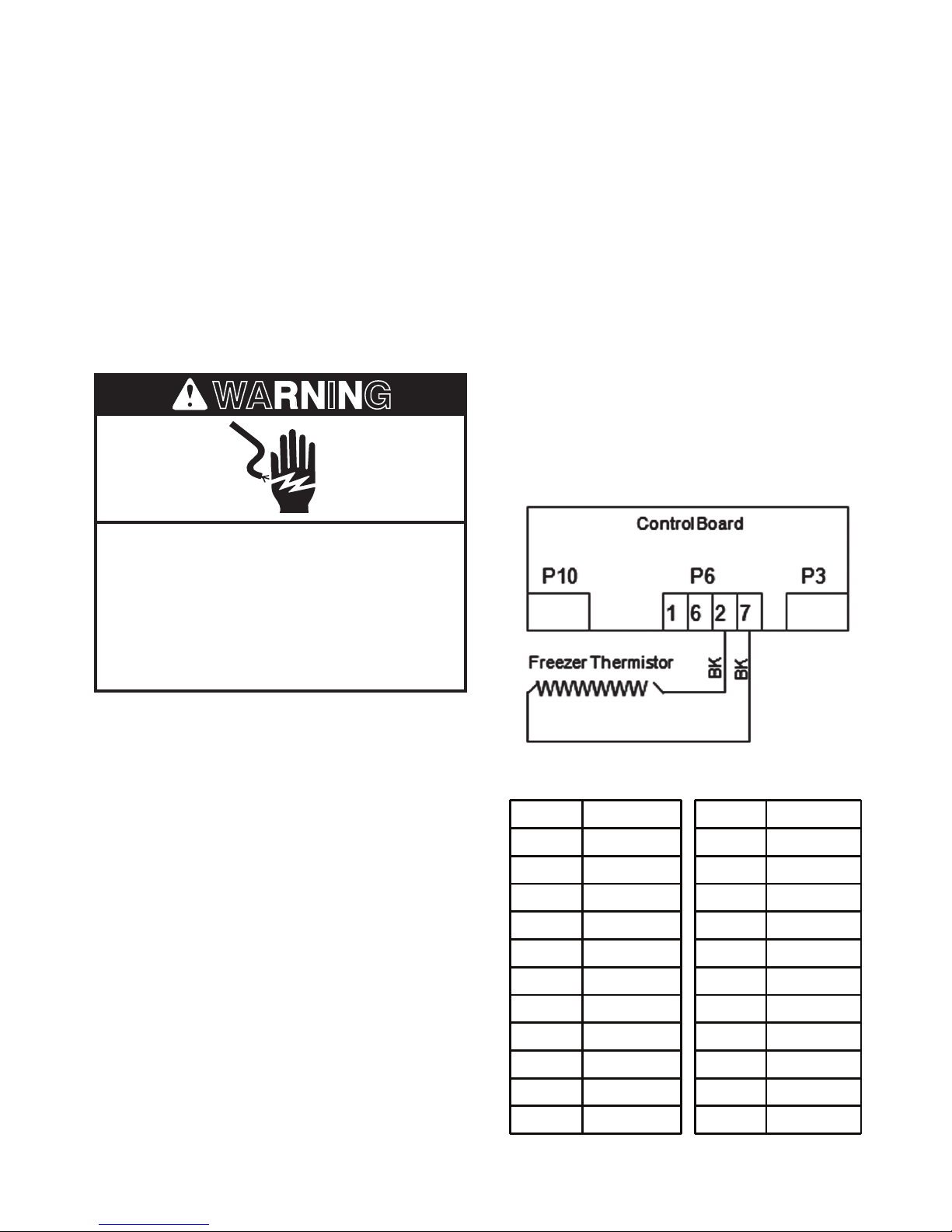
Freezer Thermistor
The freezer Thermistor is a variable resistance device connected to the control board. The
temperature of the freezer compartment causes the resistance of the Thermistor to change.
The resistance is monitored by a circuit on the control board which controls the operation of
the cooling system. The Thermistor is located on the left side of the freezer cabinet attached to
the back of the cover labeled 6
Checking the freezer Thermistor
Electrical Shock Hazard
th
sense.
Disconnect power before servicing.
Replace all parts and panels before
operating.
Failure to do so can result in death or
electrical shock.
1. Disconnect power to the refrigerator
2. Disconnect the wiring harness from
connector P6 on the control board.
3. Connect an Ohmmeter across the
2 Black wires in the disconnected
wiring harness and measure the
resistance.
4. Compare the resistance measured to the
value listed on the tech sheet shipped
with the refrigerator. Replace Thermistor
if needed.
4-1
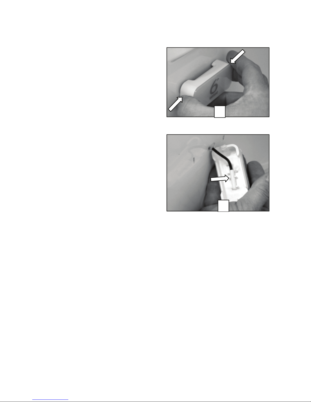
Freezer Components (continued)
1
2
Replacing Freezer Thermistor
1. Depress the tabs on either end of the
Thermistor cover and remove.
2. To replace the Thermistor order replace-
ment Thermistor kit through the normal
part ordering system by model number.
Follow the instructions supplied with the
kit.
4-2
 Loading...