

Whirlpool GR556LRKP0, YGR556LRKP0, YGR556LRKS0, GR556LRKS1, GR556LRKS0 Installation Guide
...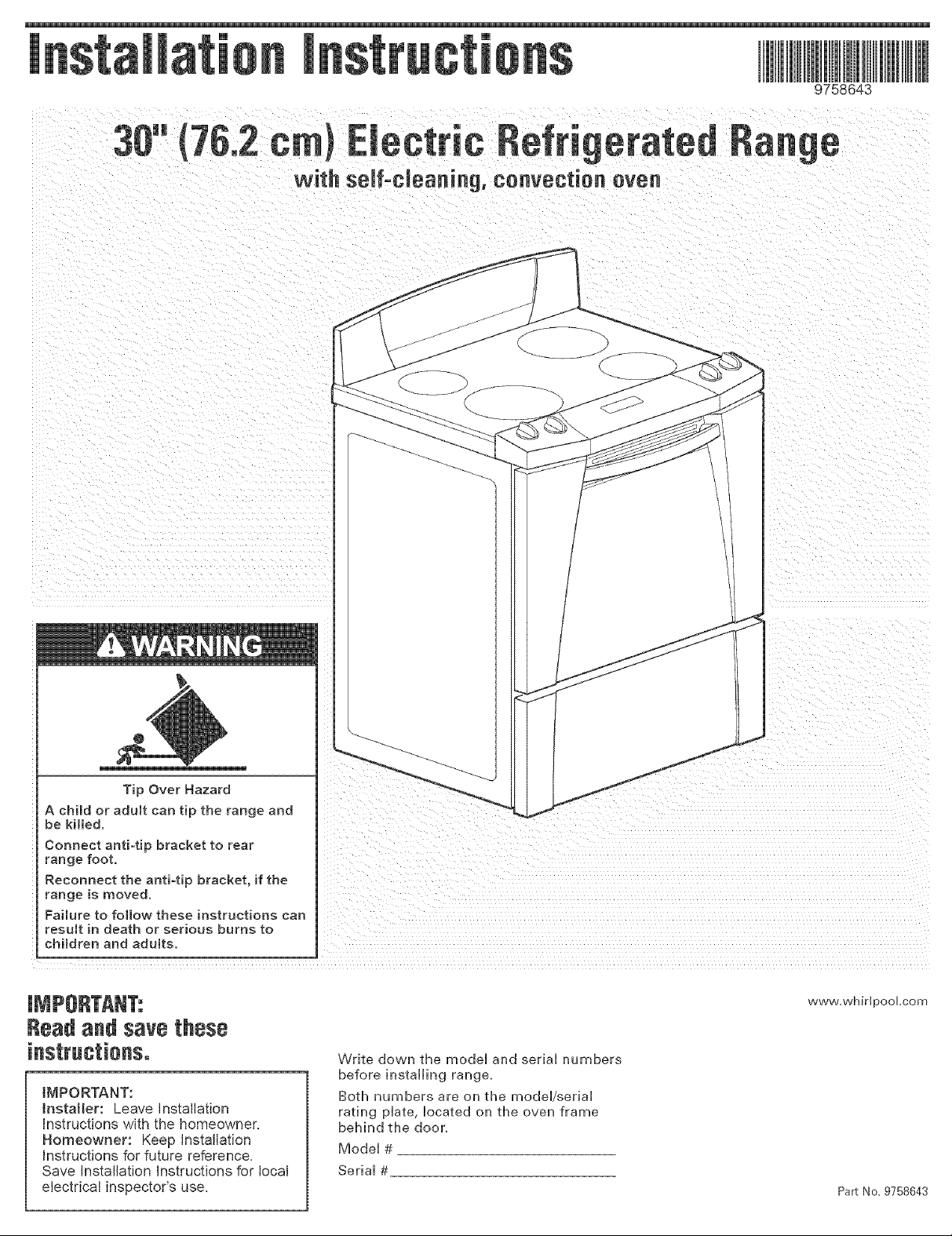
with serf°cleaning, convection even
9758643
e
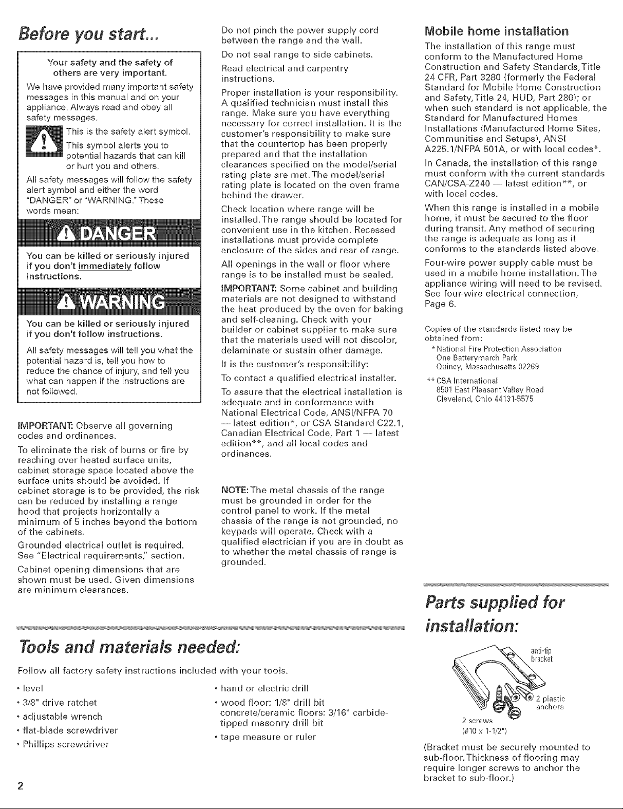
Tip Over Hazard
A child or adult can tip the range and
be killed,
Connect anti-tip bracket to rear
range foot.
Reconnect the anti-tip bracket, if the
range is moved.
Failure to fo[Iow these instructions can
result in death or serious burns to
children and adults.
Readandsave these
IMPORTANT:
Installer: Leave Installation
Instructions with the homeowner=
Homeowner: Keep Installation
instructions for future reference=
Save Installation instructions for local
electrical inspector's use=
www.whiripooLcorn
Write down the mode[ and serial numbers
before installing range,
Both numbers are on the model/serial
rating plate, located on the oven frame
behind the door,
Model #
Serial #
Part No. 9758643
Before you start...
Your safety and the safety of
others are very important.
We have provided many important safety
messages in this manual and on your
appliance. Always read and obey all
safety messages.
This is the safety alert symbol.
This symbol alerts you to
potential hazards that can kill
or hurt you and others.
All safety messages will follow the safety
alert symbol and either the word
'DANGER" or ' VVARNING." These
words mean:
You can be killed or seriously injured
if you don't immediatebL follow
instructions.
You can be killed or seriously injured
if you don't follow instructions.
Al! safety messages will tel! you what the
potential hazard is, tell you how to
reduce the chance of injury, and tell you
what can happen if the instructions are
not followed.
iMPORTANT: Observe all governing
codes and ordinances.
To eliminate the risk of burns or fire by
reaching over heated surface units,
cabinet storage space located above the
surface units should be avoided. If
cabinet storage is to be provided, the risk
can be reduced by installing a range
hood that projects horizontally a
minimum of 5 inches beyond the bottom
of the cabinets.
Grounded electrical outlet is required.
See "Electrical requirements;' section,
Cabinet opening dimensions that are
shown must be used, Given dimensions
are minimum clearances.
Do not pinch the power supply cord
between the range and the wall.
Do not seal range to side cabinets.
Read electrical and carpentry
instructions.
Proper installation is your responsibilit%
A qualified technician must install this
range. Make sure you have everything
necessary for correct installation, It is the
customer's responsibility to make sure
that the countertop has been properly
prepared and that the installation
clearances specified on the model/serial
rating plate are met.The model/serial
rating plate is located on the oven frame
behind the drawer.
Check location where range will be
installed.The range should be located for
convenient use in the kitchen. Recessed
installations must provide complete
enclosure of the sides and rear of range.
All openings in the wall or floor where
range is to be installed must be sealed.
IMPORTANT: Some cabinet and building
materials are not designed to withstand
the heat produced by the oven for baking
and self-cleaning, Check with your
builder or cabinet supplier to make sure
that the materials used will not discolor,
delaminate or sustain other damage.
It is the customer's responsibility:
To contact a qualified electrical installer.
To assure that the electrical installation is
adequate and in conformance with
National Electrical Code, ANSl/NFPA 70
-- latest edition*, or CSA Standard C22.1,
Canadian Electrical Code, Part 1 -- latest
edition **, and all local codes and
ordinances.
NOTE:The metal chassis of the range
must be grounded in order for the
control panel to work, If the metal
chassis of the range is not grounded, no
keypads will operate. Check with a
qualified electrician if you are in doubt as
to whether the metal chassis of range is
grounded.
Mobile home installation
The installation of this range must
conform to the Manufactured Home
Construction and Safety Standards, Tide
24 CFR, Part 3280 (formerly the Federal
Standard for Mobile Home Construction
and Safety, Title 24, HUD, Part 280); or
when such standard is not applicable, the
Standard for Manufactured Homes
Installations (Manufactured Home Sites,
Communities and Setups), ANSI
A225.1/NFPA 501A, or with local codes*,
In Canada, the installation of this range
must conform with the current standards
CAN/CSA-Z240 -- latest edition**, or
with local codes.
When this range is installed in a mobile
home, it must be secured to the floor
during transit. Any method of securing
the range is adequate as long as it
conforms to the standards listed above.
FouFwire power supply cable must be
used in a mobile home installation.The
appliance wiring will need to be revised.
See four-wire electrical connection,
Page 6.
Copies of the standards listed may be
obtained from:
National Fire Protection Association
One Batterymarch Park
Quincy, Massachusetts 02269
_ CSA hsternational
8501 East PleasantValby Road
Cleveland, Ohio 44131-5575
Parts supplied for
ToMs and materials needed:
Follow all factory safety instructions included with your tools.
* level
* 3/8" drive ratchet
adjustable wrench
. fiat-blade screwdriver
. Phillips screwdriver
• hand or electric drill
• wood floor: 1/8"' drill bit
concrete/ceramic floors: 3/16"' carbide-
tipped masonry drill bit
• tape measure or ruler
installation:
anti-tiPt
lastic
hors
(#10x 1-1/2")
(Bracket must be securely mounted to
sub-floor.Thickness of flooring may
require longer screws to anchor the
bracket to sub-floor.)
Cutout dimensions/requirements
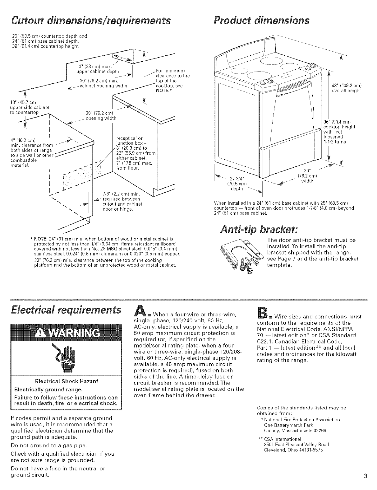
25" (63.5 cm) countertop depth and
24" (6! cm) base cabinet depth,
36" (91.4cm) countertop height
I .... jFor m,n,mum
I - _...... _ clearance to the
_'cm) min. top of the
_ning width / _'Icooktop, see
_ _..fJ I_- NOTE,*
1o6p,,45:p % t
to countertop . 30" (76.2 cm) _--_
[ j°perfing widih "_'_
I
4" (!02 cm) _'_
min. clearance from
both sides of range
to side wall or other
combustible
material I _
J
J
I
b. j
I i
,%
receptical or
junction box-
/ 8" (20.3 cm) to
22" (55.9 cm) frorr
either cabinet,
7" (lZ8 cm) max.
from floor.
7/8" (2.2 cm) rain.
required between
cutout and cabinet
door or hinge.
Product dimensions
43" (109.2 cm)
overall height
36" (91.4 cm)
cooktop height
with feet
loosened
I-1/2 turns
30 _
27-3/4"
depth
(70.5 crn) j
When installed in a 24" (61 cm) base cabinet with 25" (63.5 cm)
countertop -- front of oven door protrudes 1-7/8" {4.8 cm) beyond
24" (61 cm) base cabinet.
(762 cm)
width
* NOTE: 24" (6! cm) rain. when bottom of wood or metal cabinet is
protected by not less than 1/4" (0.64 cm) flame retardant millboard
covered with not less than No. 28 MSG sheet steel, 0.0!5" (0.4 ram)
stainless steel, 0.024" (0.6 ram) aluminum or 0.626" (0.5 mm) copper.
30" (76.2 cm) milK. clearance between the top of the cooking
platform and the bottom of an unprotected wood or metal cabinet.
Electrical requirements
Electrical Shock Hazard
EmectricaHy ground range.
Failure to follow these instructions can
resumt in death, fire, or emectrical shock.
If codes permit and a separate ground
wire is used, it is recommended that a
qualified electrician determine that the
ground path is adequate.
Do not ground to a gas pipe.
Check with a qualified electrician if you
are not sure range is grounded.
Do not have a fuse in the neutral or
ground circuit.
And-t@ bracket:
a fouFvvire or three-wire,
single- phase, 120/240-volt, 60-Hz,
AC-only, electrical supply is available, a
50 amp maximum circuit protection is
required (or, if specified on the
model/serial rating plate, when a four-
wire or three-wire, single-phase 120/208-
volt, 60 Hz, AC-only electrical supply is
available, a 40 amp maximum circuit
protection is required), fused on both
sides of the line. A time-delay fuse or
circuit breaker is recommended.The
model/serial rating plate is located on the
oven frame behind the drawer.
The floor anti-tip bracket must be
installed.To install the anti-tip
bracket shipped with the range,
see Page 7 and the anti4ip bracket
template.
Wire sizes and connections must
conform to the requirements of the
National Electrical Code, ANSl/NFPA
70 -- latest edition x_or CSA Standard
C22.1, Canadian Electrical Code,
Part 1 -- latest edition __ and aii local
codes and ordinances for the kilowatt
rating of the range.
Copies of the standards listed may be
obtained from:
National Fire Protection Association
One Batterymarch Park
Quincy, Massachusetts 02269
_ CSA hsternational
8501 East PleasantValby Road
Cleveland, Ohio 44131-5575
Electrical connection
(Not used for Canadian
installations)
This range can be connected directly to
the fused disconnect (or circuit breaker
box) through flexible, armored conduit.
Allow two to three feet of slack in the line
so that it can be moved if servbing is
ever necessary.
A U.L.-Ibted cable conduit connector
must be provided at each end of the
power supply cable (at the range and at
the junction box).
Remove the terminal block cover located
on the back of range.
nuts block cover
knockout
opening for,
40 amp
power
supply cord
Depending on your electrical supply,
make the four-wire or three-wire
connection to the range following the
"Power supply cord method" or "Direct
wire method" instructions.
\ J_/ I power
L supply cable
_f connecting to a
four-wire e_ectrica_ system...
This range is manufactured with the
ground connected to the cabinet.The
ground must be revised so the green
grounding wire of the four-wire power
supply cord is connected to the cabinet.
See "Four-wire electrical connection"
section.
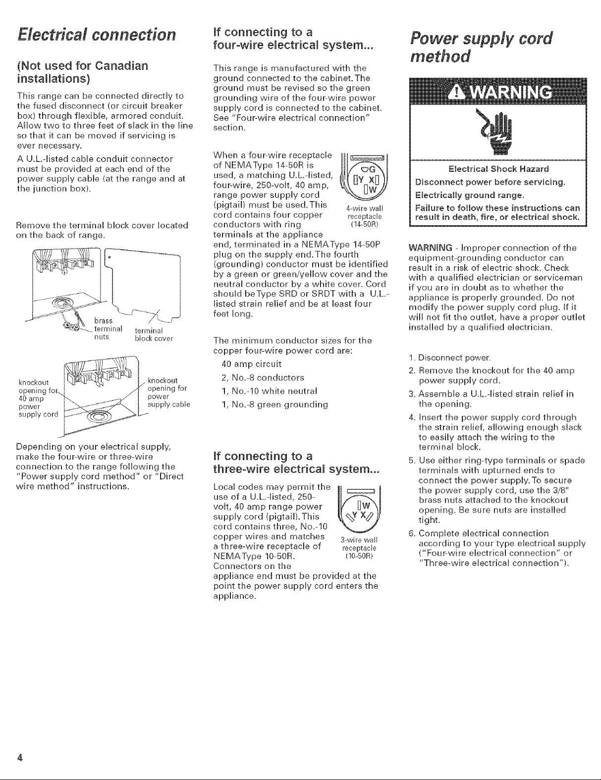
When a four-wire receptacle
of NEMAType 14-50R is
used, a matching U.L.qisted,
four-wire, 250-volt, 40 amp,
range power supply cord
(pigtail) must be used.This 4-wire wall
cord contains four copper receptacle
conductors with ring (!4-50R)
terminals at the appliance
end, terminated in a NEMAType 14-50P
plug on the supply end.The fourth
(grounding) conductor must be identified
by a green or green/yellow cover and the
neutral conductor by a white cover. Cord
shouldbeTypeSRDorSRDTwith a U.L-
listed strain relief and be at least four
feet long.
The minimum conductor sizes for the
copper four-wire power cord are:
40 amp circuit
2, No.-8 conductors
1, No.-10 white neutral
1, No.-8 green grounding
ff connecting to a
three-wire e_ectrica_ system,..
Local codes may permit the II r"""'m I
use of a U.L.-listed, 250-
volt, 40 amp range power
supply cord (pigtaib.This
cord contains three, No.-10
copper wires and matches 3-wire wall
a three-wire receptacle of receptacle
NEMAType 10-50R. (!0-50R)
Connectors on the
appliance end must be provided at the
point the power supply cord enters the
appliance.
Power supply cord
method
Electrical Shock Hazard
Disconnect power before servicing.
EmectricaHy ground range.
Failure to follow these instructions can
result in death, fire, or emectrical shock.
WARNING -Improper connection of the
equipment-grounding conductor can
result in a risk of electric shock. Check
with a qualified electrician or serviceman
if you are in doubt as to whether the
appliance is properly grounded. Do not
modify the power supply cord plug. If it
will not fit the outlet, have a proper outlet
installed by a qualified electrician.
1. Disconnect power.
2. Remove the knockout for the 40 amp
power supply cord.
3. Assemble a U.h-listed strain relief in
the opening.
4. Insert the power supply cord through
the strain relief, allowing enough slack
to easily attach the wiring to the
terminal block.
5, Use either ring-type terminals or spade
terminals with upturned ends to
connect the power supply.To secure
the power supply cord, use the 3/8"'
brass nuts attached to the knockout
opening. Be sure nuts are installed
tight.
6. Complete electrical connection
according to your type electrical supply
("Four-wire electrical connection" or
"Three-wire electrical connection").
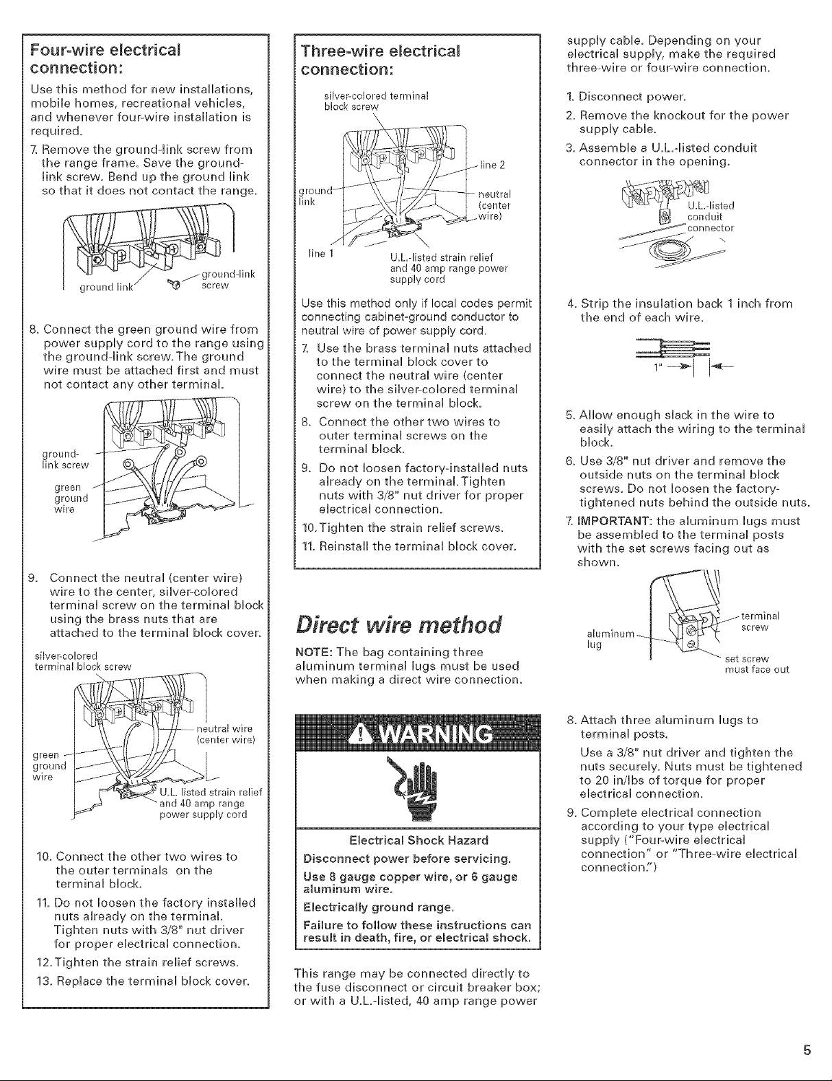
Four-wire electrical
connection:
Use this method for new installations,
mobile homes, recreational vehicles,
and whenever four-wire installation is
required.
7. Remove the ground-Hnk screw from
the range frame. Save the ground-
Hnk screw. Bend up the ground Hnk
so that it does not contact the range.
Three-wire electrical
connection:
silver-colored terminal
block screw
/line 2
- neutral
(center
..wire)
supply cable. Depending on your
electrical supply, make the required
three-wire or four-wire connection.
1. Disconnect power.
2. Remove the knockout for the power
supply cable.
3. Assemble a U.h-listed conduit
connector in the opening.
8. Connect the green ground wire from
power supply cord to the range using
the ground-link screw.The ground
wire must be attached first and must
not contact any other terminal.
link screw ('
green _I
ground /t
ground- __
wire
J
g_
Connect the neutral (center wire)
wire to the center, silver-colored
terminal screw on the terminal block
using the brass nuts that are
attached to the terminal block cover.
silver-colored
terminal block screw
-link
line I
Use this method only if !ocal codes permit
connecting cabinet-ground conductor to
neutral wire of power supply cord.
7. Use the brass terminal nuts attached
to the terminal block cover to
connect the neutral wire (center
wire) to the silver-colored terminal
screw on the terminal block.
8. Connect the other two wires to
outer terminal screws on the
terminal block.
9. Do not loosen factory-installed nuts
already on the terminal.Tighten
nuts with 3/'8"' nut driver for proper
electrical connection.
10.Tighten the strain relief screws.
11. Reinstall the terminal block cover.
U.L.-listed strain relief
and 40 amp range power
supply cord
Direct wire method
NOTE: The bag containing three
aluminum terminal lugs must be used
when making a direct wire connection.
4. Strip the insulation back 1 inch from
the end of each wire.
5. Allow enough slack in the wire to
easily attach the wiring to the terminal
block.
6. Use 3/8" nut driver and remove the
outside nuts on the terminal block
screws, Do not loosen the factory-
tightened nuts behind the outside nuts.
7.IMPORTANT: the aluminum lugs must
be assembled to the terminal posts
with the set screws facing out as
showm
aluminum_ screw
lug
terminal
set screw
must face out
eUtral wire
ground
wire
"and 40 amp range
power supply cord
10. Connect the other two wires to
the outer terminals on the
terminal blocL
11. Do not loosen the factory installed
nuts already on the terminal
Tighten nuts with 3/8" nut driver
for proper electrical connection.
12.Tighten the strain relief screws,
13. Replace the terminal block cover.
Electrical Shock Hazard
Disconnect power before servicing.
Use 8 gauge copper wire, or 6 gauge
aluminum wire.
Electrically ground range,
Failure to follow these instructions can
result in death, fire, or electrical shock.
This range may be connected directly to
the fuse disconnect or circuit breaker box;
or with a U.L-listed, 40 amp range power
8. Attach three aluminum lugs to
terminal posts.
Use a 3/8" nut driver and tighten the
nuts securely. Nuts must be tightened
to 20 in/Ibs of torque for proper
electrical connectiom
9. Complete electrical connection
according to your type electrical
supply ("Four-wire electrical
connection" or "Three-wire electrical
connection")
 Loading...