

Whirlpool GCI3061XB User Manual
®
Because Whirlpool Corporation policy includes a continuous commitment to improve
our products, we reserve the right to change materials and specifications without notice.
Dimensions are for planning purposes only. For complete details, see Installation
Instructions packed with product. Specifications subject to change without notice.
Ref. 501910200567D
10/26/10
PRODUCT MODEL NUMBERS
GCI3061X
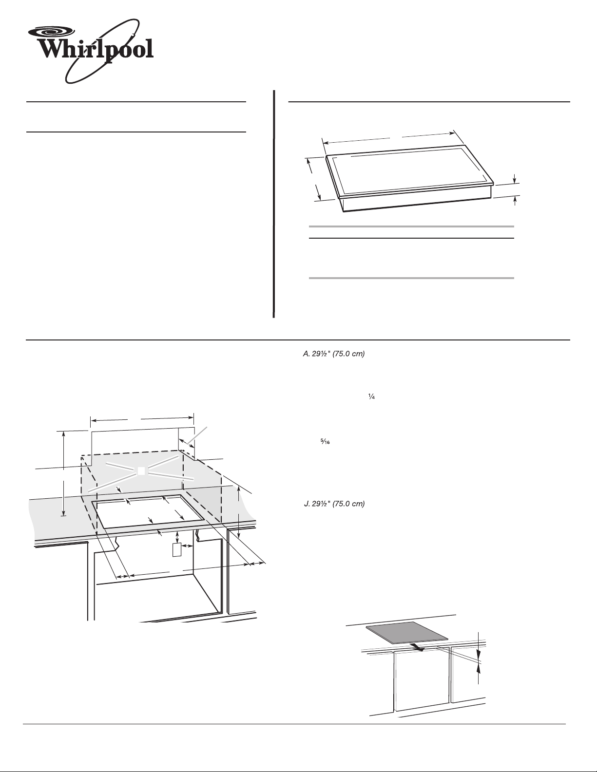
PRODUCT DIMENSIONS
ELECTRICAL REQUIREMENTS:
To properly install your cooktop, you must determine the type of
electrical connection you will be using and follow the instructions
provided for it here.
●
A 4-wire or 3-wire, single phase, 240 volt, 60 Hz., AC only electrical
supply is required on a separate, 50-amp circuit (36" [91.4 cm]
models) or 40-amp circuit (30" [76.2 cm] models), fused on both
sides of the line.
●
The cooktop should be connected directly to the junction box through
flexible, armored or nonmetallic sheathed, copper cable. The flexible,
armored cable extending from the fuse box or circuit breaker box
should be connected directly to the junction box.
●
Locate the junction box to allow as much slack as possible between
the junction box and the cooktop so that the cooktop can be moved if
servicing becomes necessary in the future.
●
Do not cut the conduit. The length of conduit provided is for
serviceability of the cooktop.
●
A UL listed or CSA approved conduit connector must be provided at
each end of the power supply cable (at the cooktop and at the junction
box). A listed conduit connector is already provided at the cooktop.
Models GCI3061
A. 21⁵⁄₁₆" (54.1 cm)
B. 30⁵⁄₁₆" (77.0 cm)
C. 2³⁄₈" (6.0 cm)
CABINET DIMENSIONS
IMPORTANT: If installing a range hood or microwave hood
combination above the range, follow the range hood or microwave hood
combination installation instructions for dimensional clearances above
the cooktop surface.
NOTES: After you make the countertop cutout, some installations may require
notching down the base cabinet side walls to clear the cooktop base. To avoid this
modification, use a base cabinet with sidewalls wider than the cutout.
If cabinet has a drawer, a 5¹⁄₈" (13 cm) depth clearance from the countertop to the
top of the drawer (or other obstruction) in base cabinet is required.
For proper ventilation, provide a vent of ³⁄₁₆" (5 mm) under the countertop, in the
front of the cabinet. The clearance should be the length of the cooktop cutout.
30" (76.2 cm) ELECTRIC INDUCTION COOKTOP
A
D
C
B
L
F
E
G
H
I
K
J
30" (76.2 cm) Cooktops
B
A
C
B. Combustible area above countertop (shown by dashed box above)
C. 30" (76.2 cm) minimum clearance between top of cooktop platform
and bottom of uncovered wood or metal cabinet (24" [61 cm]
minimum clearance if bottom of wood or metal cabinet is covered
by not less than
not less than No. 28 MSG sheet steel, 0.015" [0.04 cm] stainless
steel, or 0.024" [0.06 cm] aluminum or 0.020" [0.05 cm] copper)
D. 13" (33.0 cm) recommended upper cabinet depth
E. 2" (5.1 cm)
" (49.0 cm)
F. 1 9
G. 18" (45.7 cm) minimum clearance from upper cabinet to countertop
within minimum horizontal clearances to cooktop
H. Junction box or outlet; 12" (30.5 cm) minimum from bottom of
countertop
I. Junction box or outlet; 10" (25.4 cm) from right-hand side of
cabinet
K. 1" (2.5 cm) minimum distance to nearest left and right side
combustible surface above cooktop
L. 1" (2.5 cm) minimum clearance between back wall and countertop
" [0.6 cm] flame retardant millboard covered with
³⁄₁₆" (5 mm)
 Loading...