

Page 1
R-102
JOB AID
Part No. 8178551
2003 69˝ HIGH
COUNTER-DEPTH
SIDE-BY-SIDE
REFRIGERATOR
CONSUMER CARE TECHNICAL
EDUCATION GROUP PRESENTS
Model GC1SHAXM
Page 2

FORWARD
This Whirlpool Job Aid, “2003 69˝ High Counter-Depth Side-By-Side Refrigerator” (Part No.
8178551), provides the technician with information on the installation, operation, and service
of the 2003 69
model being serviced, refer to the “Use and Care Guide,” or “Tech Sheet” provided with the re
frigerator.
The Wiring Diagram and Strip Circuits used in this Job Aid are typical and should be used for
training purposes only. Always use the Wiring Diagram supplied with the product when servicing
the unit.
˝ High Counter-Depth Side-By-Side Refrigerator. For specific information on the
GOALS AND OBJECTIVES
The goal of this Job Aid is to provide information that will enable the service technician to properly
diagnose malfunctions and repair the 2003 69˝ High Counter-Depth Side-By-Side Refrigerator.
The objectives of this Job Aid are to:
• Understand and follow proper safety precautions.
• Successfully troubleshoot and diagnose malfunctions.
• Successfully perform necessary repairs.
• Successfully return the refrigerator to its proper operational status.
-
WHIRLPOOL CORPORATION assumes no responsibility for any repairs made
on our products by anyone other than Authorized Service Technicians.
Copyright © 2006, Whirlpool Corporation, Benton Harbor, MI 49022
- ii -
Page 3

TABLE OF CONTENTS
Page
GENERAL .............................................................................................................................. 1-1
Refrigerator Safety ............................................................................................................. 1-1
Model & Serial Number Designations ................................................................................ 1-2
Model & Serial Number Label And Tech Sheet Locations ..................................................
1-3
INSTALLATION INFORMATION
Cutout Dimensions ............................................................................................................. 2-1
Door Removal .................................................................................................................... 2-2
Water Hookup ....................................................................................................................
THEORY OF OPERATION
Overview ............................................................................................................................ 3-1
User Interface .................................................................................................................... 3-2
Electronic Control Board .................................................................................................... 3-4
Thermistors ........................................................................................................................ 3-4
Defrost Operation ............................................................................................................... 3-5
Fan Operation And Delay ...................................................................................................
In-Door Ice ......................................................................................................................... 3-7
COMPONENT ACCESS
Component Locations ........................................................................................................ 4-1
Removing A Refrigerator Or Freezer Light Bulb ................................................................
Removing The Defrost Bimetal ..........................................................................................
Removing The Refrigerator Thermistor Housing ...............................................................
Removing The Water & Ice Dispenser Board Interface .....................................................
Removing The Evaporator Tray .........................................................................................
Removing The Control Board .............................................................................................
Removing The Water Valves ..............................................................................................
Removing The Condenser Fan Motor ..............................................................................
Removing The Compressor Terminal Box,
The Relay & Overload And Run Capacitor ....................................................................4-11
..................................................................................................... 3-1
........................................................................................................ 4-1
............................................................................................ 2-1
2-6
3-6
4-2
4-3
4-4
4-5
4-7
4-8
4-9
4-10
- iii -
Page 4

COMPONENT TESTING ........................................................................................................ 5-1
Component Testing Chart ..................................................................................................
DIAGNOSTICS & TROUBLESHOOTING ............................................................................. 6-1
User Interface Failure Feedback ........................................................................................ 6-3
Troubleshooting Chart ........................................................................................................
Electronic Control Board Pin Locations ............................................................................. 6-8
User Interface Board Pin Locations ................................................................................... 6-9
Thermistor Resistance/Temperature Chart ........................................................................
5-1
6-5
6-9
WIRING DIAGRAM & STRIP CIRCUITS
Wiring Diagram .................................................................................................................. 7-1
Strip Circuits ....................................................................................................................... 7-2
TECH TIPS ............................................................................................................................. 8-1
Removing The Original Gasket ..........................................................................................
............................................................................... 7-1
8-1
- iv -
Page 5
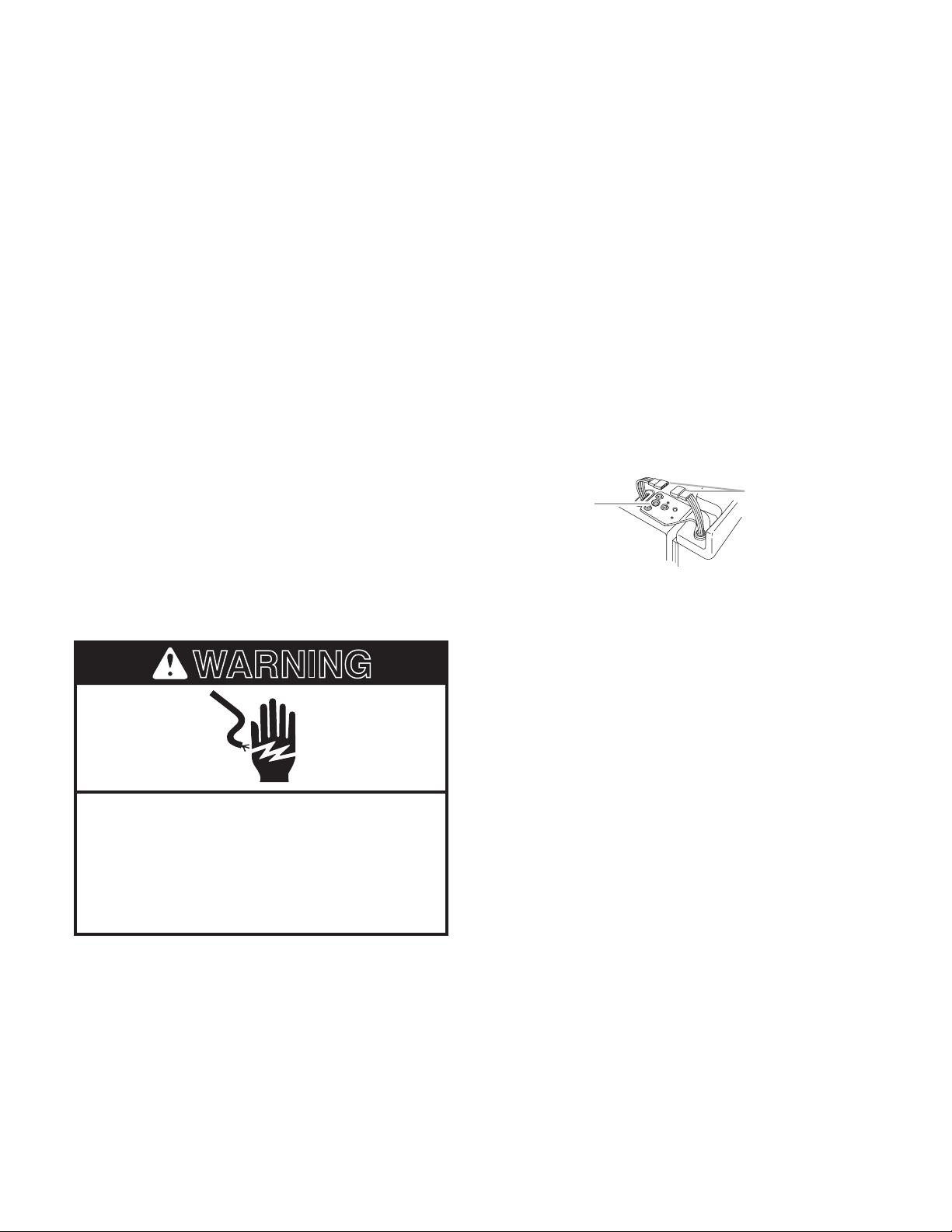
WARNING
DANGER
GENERAL
REFRIGERATOR SAFETY
Your safety and the safety of others are very important.
We have provided many important safety messages in this manual and on your
appliance. Always read and obey all safety messages.
This is the safety alert symbol.
This symbol alerts you to potential hazards that can kill or hurt you and others.
All safety messages will follow the safety alert symbol and either the word
“DANGER” or “WARNING.” These words mean:
You can be killed or seriously injured if you don’t
immediately follow instructions.
You can be killed or seriously injured if you don’t
follow instructions.
All safety messages will tell you what the potential hazard is, tell you how to reduce the chance
of injury, and tell you what can happen if the instructions are not followed.
1-1
Page 6
MODEL & SERIAL NUMBER DESIGNATIONS
MODEL NUMBER
MODEL NUMBER G C 1 S H A X M Q 0 0
PRODUCT GROUP
G = Whirlpool Gold
PRODUCT IDENTIFICATION
C = Counter Depth (24
CAPACITY / CUBIC FOOT SIZE
1 = 11 or 21
MODEL SERIES / SHELVES
S = Shelf Variation
MODEL FEATURES / PANS
H = Crisper Variation
MODEL FEATURE CODE
A = IDI W/Grille Filter
DOOR SWING
X = SXS
YEAR OF INTRODUCTION
M = 2003
COLOR CODE
Q = White
B = Black
S = Stainless
ENERGY/POWER DESIGNATOR (NUMERIC)
0 = Original, 1 = 1st Change, 2 = 2nd Change, etc.
ENGINEERING CHANGE (NUMERIC)
0 = Basic Release
1 = First Revision
2 = Second Revision
˝ Deep)
SERIAL NUMBER
SERIAL NUMBER SA R 48 10001
MANUFACTURING RESPONSIBILITY
SA = Fort Smith, AR
YEAR OF PRODUCTION
R = 2004
WEEK OF PRODUCTION
48th Week
PRODUCT SEQUENCE NUMBER
1-2
Page 7
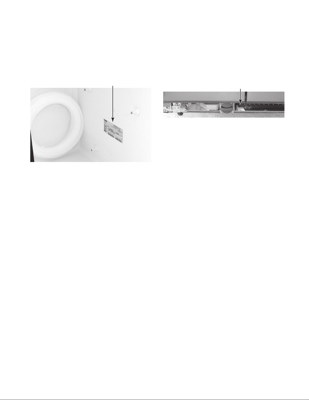
MODEL & SERIAL NUMBER LABEL
AND TECH SHEET LOCATIONS
The Model/Serial Number label and Tech Sheet locations are shown below.
Model & Serial Number Label Location
(On Lower Right Side Of Refrigerator Liner)
Tech Sheet Location
(Behind Grille)
1-3
Page 8

— NOTES —
1-4
Page 9
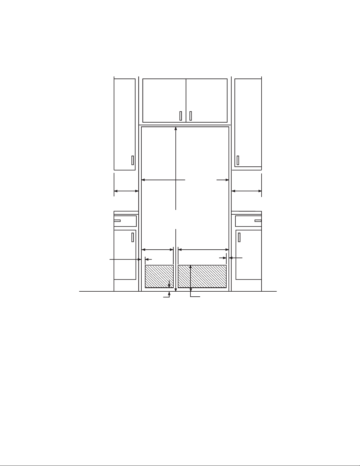
INSTALLATION INFORMATION
21/2"
(6.4 cm
)
2"
(5.1 cm
)
2"
(5.1 cm
)
91/4"
(23.5 cm
)
12
1
/
2
"
(32 cm
)
69"
(175.0 cm
)
36
"
(91.5 cm)
13
1
/
4
"
(34 cm)
16
1
/
2
"
(42 cm)
20
1
/4"
(51.5 cm)
CUTOUT DIMENSIONS
2-1
Page 10
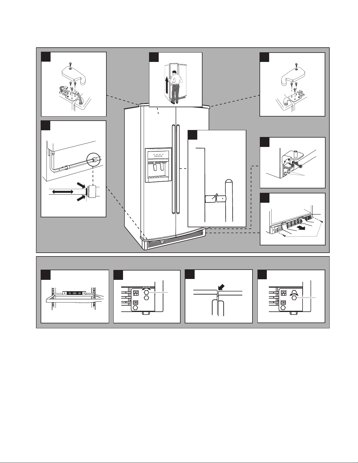
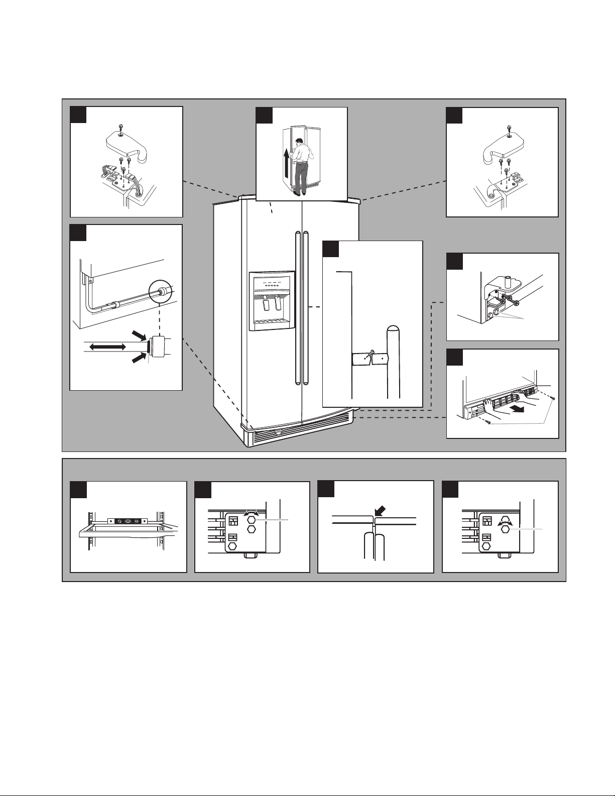
DOOR REMOVAL
WARNING
1. Do not remove screw 1
2. Wiring plug
1
2
TOOLS REQUIRED
1/2ʺ & 5/16ʺ Hex-Head Socket Wrenches
Flat-Blade Screwdriver
#1 & #2 Phillips Screwdrivers
BEFORE YOU BEGIN
Turn the refrigerator control OFF. Unplug the
refrigerator or disconnect power. Remove the
food and any adjustable door or utility bins
from the doors.
HANDLE REMOVAL (OPTIONAL)
1. Using a Phillips screwdriver, remove the
screws located on the inside of each door
handle. Pull the door handle straight out
from the door (see Illustration 1). Save the
screws for reattaching the handles.
2. To make the cabinet flush, use a flat-blade
screwdriver, and remove the screws at
taching the door handle posts to the re
frigerator cabinet. Reverse the procedure
to replace the handles.
3. Close both doors and keep them closed
until you are ready to lift them off the cabinet.
4. If you have a dispenser (ice or water),
disconnect the water dispenser tubing,
located behind the base grille on the freezer
door side (see Illustration 3). To do this,
press the red outer ring against the face
of the fitting, and pull the dispenser tubing
free. NOTE: On some models, you will
have to remove the tubing from a hose
clip.
5. Remove the top left hinge screw and cover
as shown (see Illustration 4).
6. Disconnect the wiring plug as shown.
-
-
DOOR REMOVAL
Electrical Shock Hazard
Disconnect power before removing
doors.
Failure to do so can result in death or
electrical shock.
1. Unplug refrigerator or disconnect power.
2. Open both doors and remove the two
screws from the base grille. Pull the base
grille forward and remove it (see Illustra
tion 2).
7. Remove the remaining left hinge screws
and hinge (see Illustration 4).
8. Carefully lift the freezer door straight up
and off the bottom hinge (see Illustration
5). The water dispenser tubing will remain
attached to the freezer door, and will pull
through the bottom left hinge. Make sure
that you protect the dispenser tubing from
damage when you set the door on the
floor.
9. Remove the top right hinge cover and
screws (see Illustration 6).
10. Lift the refrigerator door straight up and
off the bottom hinge.
11. Disassemble the hinges as shown (see Il
lustration 7). Do not remove the screws.
-
-
2-2
Page 11
2
Base Grille
10
Door Alignment
8
Level
9
Rear Leveling
1. Rear roller leveling screw
11
Front Leveling
1. Front roller leveling screw
Door Closing and Alignment
6
Top Right Hinge
Bottom Hinge
7
1. Do Not Remove Screws
1. Screws
Handle Removal
(Optional)
1
4
3
Water Dispenser
Tubing Connection
1. Red Outer Ring
1
5
Door Removal
1
1
Top Left Hinge
1
1
2-3
Page 12
DOOR AND HINGE REPLACEMENT
1. Do not remove screw 1
2. Wiring plug
1
2
DOOR CLOSING AND ALIGNMENT
1. If removed, replace both bottom hinges
and tighten the screws.
2. Carefully feed the dispenser tubing through
the bottom left hinge before replacing the
freezer door on the hinge.
NOTE: Provide additional support for the doors
while the top hinges are being replaced. Do not
depend on the door magnets to hold the doors
in place while you are working.
3. Reconnect the water dispenser tubing
by pushing the tubing into the fitting until
it stops, and the black mark touches the
face of the fitting (see Illustration 3). On
some models, replace the tubing in the
hose clip.
4. Align and replace the top left hinge (see
Illustration 4) and tighten the screws.
5. Reconnect the wiring plug.
6. Replace the left hinge cover and screws.
7. Carefully lift the refrigerator door and set
it on the bottom right hinge.
8. Align and replace the top right hinge (see
Illustration 6).
9. Replace the hinge cover and screws.
10. Plug in refrigerator or reconnect power.
Door Closing
1. Move the refrigerator into its final position.
2. Place a level inside the refrigerator at the
back of the top shelf (see Illustration 8).
3. Locate the leveling screws behind the base
grille of the refrigerator on either side.
4. Use a hex-head socket wrench and adjust
the rear roller leveling screws until the
refrigerator is level. Turn the rear roller
leveling screw to the right to raise that
side of the refrigerator, or to the left to
lower it (see Illustration 9). Make sure the
refrigerator is level before proceeding.
Door Alignment
If the doors are uneven after leveling the
refrigerator (see Illustration 10), perform the
following steps.
1. Use a hex-head socket wrench and adjust
the front roller leveling screws until the
doors are even. Turn the front roller leveling
screw to the right to raise that side of the
refrigerator, or to the left to lower it (see
Illustration 11).
NOTE: Open and close both the refrigerator
and freezer doors after each adjustment to
check the door alignment.
2. Open the doors and replace the base
grille. Align the grille with the bottom of the
cabinet and reattach with the screws.
NOTE: Be sure to refasten the Tech Sheet
behind the base grille.
2-4
Page 13
2
Base Grille
10
Door Alignment
8
Level
9
Rear Leveling
1. Rear roller leveling screw
11
Front Leveling
1. Front roller leveling screw
Door Closing and Alignment
6
Top Right Hinge
Bottom Hinge
7
1. Do Not Remove Screws
1. Screws
Handle Removal
(Optional)
1
4
3
Water Dispenser
Tubing Connection
1. Red Outer Ring
1
5
Door Removal
1
1
Top Left Hinge
1
1
2-5
Page 14
WATER HOOKUP
READ ALL DIRECTIONS COMPLETELY
BEFORE YOU BEGIN.
IMPORTANT:
In order to prevent possible leakage resulting
in property damage, be sure:
1. If you are operating the refrigerator before
installing the water connection, turn the
ice maker to the OFF position to prevent
operation without water.
2. Use copper tubing.
3. Install tubing only in areas where temperatures will remain above freezing.
4. All installations must be in accordance with
local plumbing code requirements.
5. See the “Installation Guide” for further
information.
COLD WATER SUPPLY
The ice maker water valve contains a flow washer which is used as a water pressure regulator.
The ice maker needs to be connected to a cold
water line with water pressure between 30-120
psi. If you have questions about your water
pressure, call a licensed, qualified plumber.
If your refrigerator has a water filter car-
•
tridge, it may further reduce the water
pressure when used in conjunction with
a reverse osmosis system. Remove the
water filter cartridge.
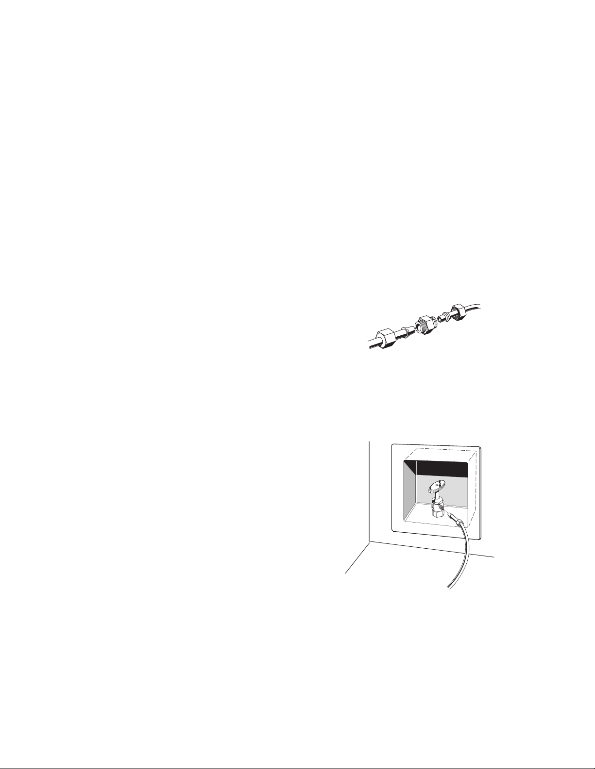
CONNECTING TO THE
REFRIGERATOR
1. Unplug refrigerator or disconnect power.
2. Remove the shipping tape from the gray,
coiled water tubing on the rear of the re
frigerator.
Style 1
1. Thread the provided nut onto the coupling
on the end of the copper tubing.
Style 2
1. Thread the provided nut onto the water
valve, as shown. First tighten the nut by
hand, then tighten it with a wrench two
more turns. Do not overtighten.
-
REVERSE OSMOSIS WATER
SUPPLY
IMPORTANT: The pressure of the water sup-
ply coming out of a reverse osmosis system
going to the water inlet valve of the refrigerator
needs to be between 30-120 psi. If a reverse
osmosis water filtration system is connected
to your cold water supply, the water pressure
to the reverse osmosis system needs to be a
minimum of 40 - 60 psi. If the water system to
the reverse osmosis water system is less than
40 - 60 psi:
Check to see whether the sediment filter
•
in the reverse osmosis system is blocked.
Replace the filter if necessary.
•
Allow the storage tank on the reverse
osmosis system to refill after heavy us
age.
FINAL CHECKS
1. Turn water supply valve ON and check for
leaks. Tighten any connections or nuts that
leak (including connections at the valve).
2. Plug in refrigerator or reconnect power.
-
NOTE: It may take up to 24 hours for the
ice maker to begin producing ice.
2-6
Page 15

THEORY OF OPERATION
OVERVIEW
The design of the 69ʺ tall counter-depth sideby-side refrigerator is similar to freestanding
side-by-side refrigerators. There are, however,
some very unique and important differences.
This section will review the operation of this
product and explain those unique differences.
The control system consists of an electronic
user interface, located on the ice and water
dispenser, an electronic control board, located
at the left rear of the unit compartment, and
thermistors, located in the refrigerator and
freezer compartments. These controls com
municate with each other, and manage virtually
all of the functions of this refrigerator, with the
exception of the in-door ice making feature.
-
3-1
Page 16
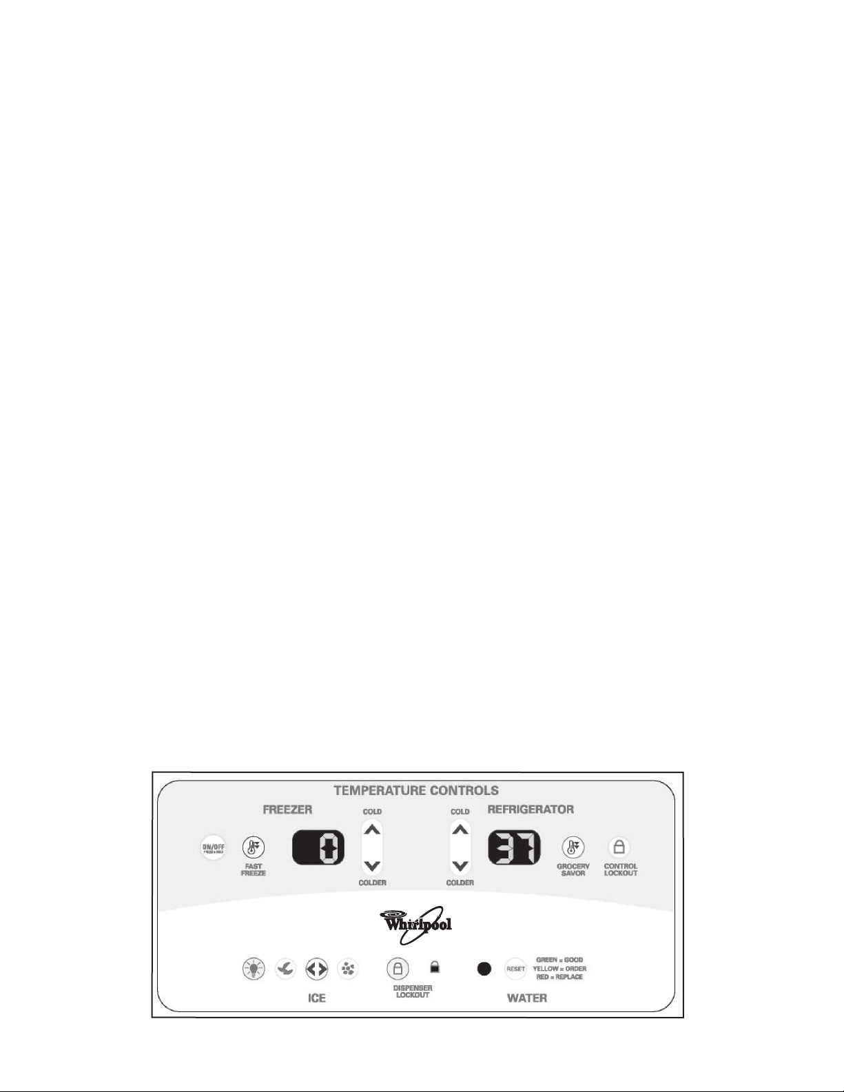
USER INTERFACE
The user interface allows the customer to
adjust the temperatures, choose what kind of
ice to be dispensed, and monitor the remain
ing water filter capacity. There are also lockout
modes for the temperature controls and the ice
and water dispenser. The temperatures are
only displayed in Fahrenheit.
Each function is described below.
ON/OFF—Press the keypad for 2 seconds to
turn the unit on and off.
When the unit is turned “off”:
• Only the central decimal point shows in
both temperature displays.
• All functions are disabled.
• All lamps and lights are off.
When the unit is turned “on”:
• All functions are restored at power-up.
• Temperature settings before powerdown are remembered.
• Fast Freeze and/or Grocery Savor
mode will be discontinued after powerup, if selected prior to power-down.
• The compressor will wait 7 minutes to
start.
• The condenser fan will wait 1 minute to
start after the compressor starts.
NOTE: At the first power-up, the control will
start in the following DEFAULT operating
-
mode:
• Unit is in the “On” state.
• Freezer temperature is set at 0ºF; Re
frigerator temperature set at 37ºF.
• Self Diagnostic Mode enabled for 10
minutes.
• Ice in Cube mode.
• Dispenser light “off”.
• Time to defrost will be set at 30 hours of
compressor run time, or 50 hours actual
time.
FREEZER (Temperature Settings)—Adjust
ment ranges from –5
COLD or COLDER keypad is pressed, the set
temperature will raise or lower 1
shows only the set temperature.
REFRIGERATOR (Temperature Settings)—
Adjustment ranges from 33
time the COLD or COLDER keypad is pressed,
the set temperature will raise or lower 1
display shows only the set temperature.
FAST FREEZE—Pressing this keypad places
the freezer section into continuous cool-down
mode for 24 hours. The control will then return
to the last freezer set temperature. While in
this mode, the FAST FREEZE keypad is illumi
nated. Pressing the keypad a second time will
terminate the FAST FREEZE mode. The refrig
erator section temperature is not affected.
°F to +5°F. Each time the
°F. The display
°F to 41°F. Each
-
-
°F. The
-
-
3-2
Page 17

GROCERY SAVOR—Pressing this keypad
places the refrigerator section into continuous
cool-down mode for 6 hours. The temperature
is regulated down to 33°F. After the 6 hour period, the control returns to the last refrigerator
set temperature. Pressing the keypad a second
time will terminate the GROCERY SAVOR
mode. While in this mode, the GROCERY
SAVOR keypad is illuminated.
CONTROL LOCKOUT—Pressing this keypad
for 2 seconds disables all user interface control
keypads relating to temperature regulation.
While in this mode, the CONTROL LOCKOUT
keypad is illuminated. If any other keypad is
pressed, the LOCKOUT keypad indicator will
blink twice. Pressing the CONTROL LOCKOUT
keypad again for 2 seconds, will enable all
temperature control functions.
DISPENSER LIGHT—Pressing this keypad
will turn the dispenser light on. Pressing the
keypad again will turn off the light. When in the
“off” mode, the light will illuminate when either
dispenser paddle is pressed.
ICE MODE—This keypad toggles between
cubed and crushed ice. In the cubed mode,
the CUBED ICE indicator will illuminate. In the
crushed mode, the CRUSHED ICE indicator
will illuminate.
DISPENSER LOCKOUT—Pressing this key
pad for 2 seconds disables the ice and water
dispenser functions, and the related user inter
face control keypads. While in this mode the
DISPENSER LOCKOUT keypad is illuminated.
If any other dispenser keypad or dispenser
paddle is pressed, the LOCKOUT keypad indi
cator will blink twice. Pressing the DISPENSER
LOCKOUT keypad again for 2 seconds will
enable all of the dispenser functions.
WATER FILTER INDICATOR—The water filter
indicator function is the same as on other Whirl
pool refrigerators with filtered water systems.
Pressing the RESET keypad for 2 seconds
will reset the indicator back to green, and the
counter will start over. The filter indicator can
only be reset when the filter indicator light is
“red,” no matter when the filter is changed.
Maximum filter capacity is 400 gallons, or for
a time period not to exceed 6 months.
-
-
-
-
3-3
Page 18

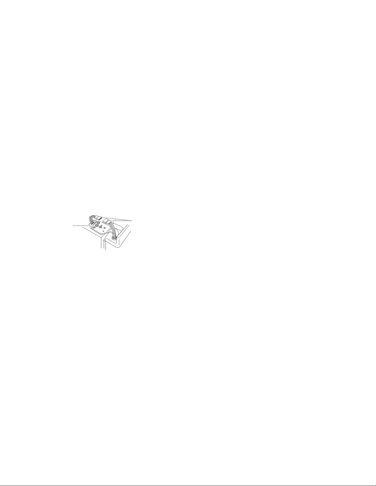
ELECTRONIC CONTROL BOARD
The main electronic control board is located
at the right rear of the unit compartment (fac
ing from the rear). The main electronic board
communicates with the user interface. It also
receives and reacts to feedback from other
THERMISTORS
Temperature is regulated with the use of two
thermistors that provide feedback to the main
control board. One thermistor is located on the
back wall of the refrigerator section, and the
other is located on the left wall of the freezer
section.
NOTE: Thermistors are very reliable and seldom fail.
sources, such as water valves, thermistors,
defrost bimetal, refrigerator and freezer light
switches, and the air damper. The electronic
control board directly controls, or supplies power
to, virtually all functions of the refrigerator.
The refrigerator thermistor controls:
• Motorized air baffle (damper)
• Evaporator fan (only when the air baffle
is open)
The freezer thermistor controls:
• Compressor
• Condenser fan
• Evaporator fan (only when the air baffle
is closed)
3-4
Page 19

DEFROST OPERATION
Defrost is controlled by the main control board,
and incorporates the use of the “pulsed” de
frost. However, this defrost system is uniquely
different than other Whirlpool electronic refrig
erators.
• Defrost is initiated by a different set of
criteria (listed below).
• The bimetal/thermofuse combination
switches off the defrost heater, and
provides additional defrost circuit pro
tection.
• The defrost bimetal is placed on the
neutral side of the defrost heater, and
the thermofuse protects the “line” side
of the circuit.
• The electronic control does not “timeout” and terminate the defrost cycle.
Defrost is terminated only by the open
ing of the bimetal switch contacts, or the
opening of the thermofuse in case the
bimetal fails.
• The bimetal opens at 45
and closes at 19°F ±5° (–7°C ±3°).
• The thermofuse will open at 162
(72°C).
The defrost cycle is initiated:
• When power is connected (after the
initial power-up) to the refrigerator and
the bimetal is closed (unit is cold).
• With no door openings.
- When 30 hours of compressor run
time, or 50 hours actual time, has
passed since the last defrost cycle.
°F ±5° (7°C ±3°)
°F
• If a door was opened.
-
-
The following occurs when the defrost cycle
is initiated:
-
-
When defrost bimetal thermostat opens:
- After 8 hours of cumulative compres
sor run time.
• The compressor runs continuously for
at least 8 hours.
• Cooling function switches OFF (compressor and both fans are OFF).
• The air-baffle/damper switches to the
CLOSED position.
• The heater starts to heat the evaporator
with the following timing:
- 5 minutes ON, 1 minute OFF.
- 3 minutes ON, 1 minute OFF repeat-
edly.
- Bimetal thermostat opens at 45°F ±5°
(7°C ±3°).
• The defrost heater is switched OFF.
• The compressor is activated after
7 minutes of drip time.
• The condenser fan is activated 1 minute
after the compressor.
• The evaporator fan is activated after
10 minutes from bimetal opening, or
3 minutes after the compressor starts.
• The air baffle is opened 3 minutes after
the compressor is activated, or a total
time of 10 minutes from the bimetal
opening.
-
3-5
Page 20

FAN OPERATION AND DELAY
Both the condenser and evaporator fan motors operate on DC voltage. The control board
supplies 115 volts AC to each motor, where it
is converted to DC.
EVAPORATOR FAN
• Fan Start Delay—Fan is energized
3 minutes after the compressor starts.
• Fan Stop Delay—Fan is switched OFF
1 minute after the compressor stops.
• IMPORTANT: Evaporator fan shuts off
when either the refrigerator or freezer
door is opened.
CONDENSER FAN
• Fan start delay—Fan is energized
1 minute after the compressor starts.
• Fan stops when the compressor shuts
off.
POWER FAILURE / TEMPERATURE RISE
This product has no audible alarm. However, it
will alert the customer of a long power outage,
or temperature rise, if the temperature rises
above 17.6
following will happen:
• The “alert” will only be indicated on the
• The freezer temperature display blinks
• The actual compartment temperature
• All settings and memory are saved and
°F (–8°C). Should this occur, the
freezer temperature display.
continually, and will show the actual
freezer compartment temperature from
the time the power is restored. If there
are consecutive outages, the display
will show the highest temperature for
the entire period.
will display until the freezer COLD or
COLDER keypad is pressed. The “alert”
is terminated, and the display will revert
back to the set temperature.
are continued after power has been restored, i.e. FAST FREEZE, GROCERY
SAVOR, and ice preference.
DEFAULT SETTINGS
If communication between the user interface
and the control board is lost for more than
3 minutes, the user interface assumes the
board is working correctly. The control board
stores the current temperature settings, but
will go into a “default mode,” and maintain
preset temperatures. Once communication is
restored, the stored settings are again used.
If communication is broken between the user
interface and the control board during an “ON”
cycle:
Electronic Control
• Default temperatures that will be maintained are:
- Refrigerator section: 41
- Freezer section: 0
User Interface
• Freezer display flashes “CF” and Set
Temp alternately (Communication
Fault).
• Refrigerator display flashes the Set
Temperature.
• The user interface keypads will be dis
abled
• The ice maker will be disabled.
• The water filter status indicator light
will blink, and the reset keypad will be
disabled.
• The refrigerator and freezer interior
lights will be off, except for the indicators
above.
Default Operation If Thermistors Fail:
• Refrigerator thermistor fails:
- Damper and evaporator fan will be
cycled “on” 15 minutes and “off”
30 minutes.
• Freezer thermistor fails:
- Compressor and evaporator fan will
run continuously.
°F (5°C).
°F (–18°C).
-
3-6
Page 21

IN-DOOR ICE
IMPORTANT:
The In-Door Ice (IDI) feature and function on
this product is the same as on all other IDI
refrigerators.
Although physically interchangeable with other
IDI electronic controls, these control boards
are unique to this product and will not function
in other IDI product, nor will other IDI controls
function in this product.
If replacement controls are needed, order by
model number.
The IDI control board and the ice maker are
powered directly from the control board. This
allows the main control board to monitor the ice
maker water fill, and the closing of the freezer
light switch when the door is opened. When
the freezer door is opened, the ice maker is
temporarily disabled.
The IDI diagnostic routine is also identical, and
the checkout procedure is the same. For more
information on diagnostics, or IDI design and
function, refer to Job Aid #4322658A.
3-7
Page 22

— NOTES —
3-8
Page 23

COMPONENT ACCESS
WARNING
This section instructs you on how to service components inside the 2003 69˝ High Counter-Depth
Side-By-Side Refrigerator. The components and their locations are shown below.
of the components called out below are not serviced in this section.
COMPONENT LOCATIONS
Electrical Shock Hazard
Disconnect power before servicing.
Replace all parts and panels before operating.
Failure to do so can result in death or electrical shock.
NOTE: Some
Ice Maker
Freezer Light
Freezer Thermistor
Defrost Bimetal (Behind Evaporator Cover)
User Interface
Evaporator Tray (Behind Grille)
Compressor Terminal Box
Overload & Relay
Water Valves
Condenser Fan Motor
Refrigerator Light
Air Door
Refrigerator Thermistor
Water Reservoir Tubing
Control Board Assembly
4-1
Page 24

REMOVING A REFRIGERATOR OR FREEZER LIGHT BULB
1. Unplug refrigerator or disconnect power.
2. To remove the freezer light bulb:
a) Unhook the four tabs from the light cover
(located behind the in-door ice maker)
and remove the cover.
Freezer Light Cover
b) Pull the light bulb out of the socket.
Freezer Light Bulb
3. To remove the refrigerator light bulb:
a) Remove the screw from the lens.
b) Lower the back of the lens and unhook
the three tabs from the liner slots.
Refrigerator Light Lens Light Bulb
Lens Screw
c) Pull the light bulb so that the terminals
are free of the socket and remove the
bulb.
4-2
Page 25

REMOVING THE DEFROST BIMETAL
WARNING
7. Lift the top evaporator cover and unhook
the two tabs from the slots in the cover,
then pull the cover up around the drawer
slides, and out of the unit.
Top Evaporator Cover
Electrical Shock Hazard
Disconnect power before servicing.
Replace all parts and panels before
operating.
Failure to do so can result in death or
electrical shock.
1. Unplug refrigerator or disconnect power.
2. Remove the food and shelves from the
freezer compartment.
3. Pull forward on center of the top air guide.
Unsnap the four liner catches from the
guide supports, and remove the guide.
Liner Catch
(1 of 4)
Pull
Out
Air Guide
2 Tabs
In Slots
Screw (1 of 4)
2 Shelf
Supports
Screw (1 of 4)
Bottom
Evaporator
Cover
8. Cut the indicated wire tie from around the
defrost bimetal wires and tubing.
9. Disconnect the two heater connectors and
the evaporator fan motor connector from
the defrost bimetal.
10. Unsnap the defrost bimetal from the evaporator tubing and disconnect the ground
wire and 5-wire connector from the liner.
4. Remove the screw from each of the two
indicated shelf supports and remove
the supports (see the top right column
photo).
5. Remove the four screws from the top
evaporator cover.
6. Remove the four screws from the bottom
evaporator cover and remove the cover.
Evaporator Fan
Motor Connector
Heater Connectors
5-Wire
Connector
Wire Tie
Defrost Bimetal
4-3
Page 26

REMOVING THE REFRIGERATOR THERMISTOR HOUSING
WARNING
4. Unclip the refrigerator thermistor and wire
from the housing.
5. Place the thermistor in ice water (refer to
page 6-9 for the correct readings).
Electrical Shock Hazard
Disconnect power before servicing.
Replace all parts and panels before
operating.
Failure to do so can result in death or
electrical shock.
Refrigerator Thermistor
1. Unplug refrigerator or disconnect power.
2. Remove the food and shelf that is in front
of the refrigerator thermistor.
3. Remove the screw from the refrigerator
thermistor housing and turn the housing
over.
Unclip
Refrigerator Thermistor Housing Screw
4-4
Page 27

REMOVING THE WATER & ICE
WARNING
DISPENSER BOARD INTERFACE
Electrical Shock Hazard
Disconnect power before servicing.
Replace all parts and panels before
operating.
Failure to do so can result in death or
electrical shock.
1. Unplug refrigerator or disconnect power.
Push
Down
Pull
Out
2. Lift the overflow tray from the water and
ice dispenser.
Overflow Tray
3. Push down on the bottom of the front cover
housing of the water and ice dispenser,
then pull the housing out at the bottom,
and unhook it at the top (see the top photo
in the right column).
4. Disconnect the two edge connectors from
the board interface and remove the hous
ing assembly.
Board Interface Edge Connectors
Continued on the next page.
-
4-5
Page 28

5. Remove the three screws from the interface
board cover and remove the cover.
Board Interface Cover Screws
IMPORTANT: Due to static electricity, always
handle circuit boards by the edges to avoid
damage to the circuitry.
6. Remove the two screws from the interface
board and remove the board from the
housing.
Interface Board Screws
Interface Board
4-6
Page 29

REMOVING THE EVAPORATOR TRAY
WARNING
Electrical Shock Hazard
Disconnect power before servicing.
Replace all parts and panels before
operating.
Failure to do so can result in death or
electrical shock.
NOTE: The evaporator tray is not customer
removable.
1. Unplug refrigerator or disconnect power.
2. Remove the two screws from the bottom
grille and remove the grille.
3. Remove the two 9/32
screws from the filter bracket, and push
the bracket assembly to the right as far as
it will go.
Filter Bracket Screws
4. Pull the evaporator tray out from below
the unit and remove it.
ʺ (7 mm) hex-head
Bottom Grille Screws
Evaporator
Tray
4-7
Page 30

REMOVING THE CONTROL BOARD
WARNING
Electrical Shock Hazard
Disconnect power before servicing.
Replace all parts and panels before
operating.
Failure to do so can result in death or
electrical shock.
1. Unplug refrigerator or disconnect power.
2. Remove the six screws from the unit compartment cover and remove the cover.
4. Using a small screwdriver, start at the top
of the cover, and pry the tabs on the hous
ing from the loops on the cover. When all
the loops are free, remove the cover.
Top Of Housing Cover Open
-
Unit Compartment Cover Screws (3 of 6)
3. Remove the two screws from the control
board housing cover and pull the assembly
out of the unit.
Control Board Housing
Cover Screws
5. Remove the four screws from the control
board.
6. Disconnect the wire connectors from the
control board and remove it from the hous
ing.
Wire Connectors
4 Control Board Screws
-
4-8
Page 31

REMOVING THE WATER VALVES
WARNING
3. Disconnect the two water outlet lines from
the water valves.
4. Disconnect the four electrical connectors
from the valve terminals. NOTE: One
valve has 3/16
has 1/4
reversed.
ʺ terminals so that they cannot be
ʺ terminals and the other
Electrical Shock Hazard
Disconnect power before servicing.
Replace all parts and panels before
operating.
Failure to do so can result in death or
electrical shock.
1. Unplug refrigerator or disconnect power.
2. Remove the six screws from the unit compartment cover and remove the cover.
Unit Compartment Cover Screws (3 of 6)
5. Remove the two 9/32ʺ hex-head screws
from the valve bracket.
6. Disconnect the two water inlet lines from
the water valves and remove the valve
assembly from the unit.
Bracket
Screws
Brn & Blk Connectors
Blu & Wht Connectors
Water Outlet Lines
4-9
Water Inlet Lines
Page 32

REMOVING THE CONDENSER FAN MOTOR
WARNING
Electrical Shock Hazard
Disconnect power before servicing.
Replace all parts and panels before
operating.
Failure to do so can result in death or
electrical shock.
1. Unplug refrigerator or disconnect power.
2. Remove the six screws from the unit compartment cover and remove the cover.
4. Remove the three Torx (#15) screws from
the condenser fan motor and remove the
motor from the bracket.
Fan Motor Torx
Screws (2 of 3)
Unit Compartment Cover Screws (3 of 6)
3. Using a 9/16ʺ socket, remove the hex-nut
and fan blade from the condenser fan mo
tor.
Fan Blade
9/16ʺ Socket
5. Disconnect the wire connector from the
fan motor.
-
Fan Motor Connector
4-10
Page 33

REMOVING THE COMPRESSOR TERMINAL BOX,
WARNING
THE RELAY & OVERLOAD AND RUN CAPACITOR
4. To remove the compressor terminal
box:
a) Use a screwdriver and pry the top of the
terminal box away from the compres
sor.
-
Electrical Shock Hazard
Disconnect power before servicing.
Replace all parts and panels before
operating.
Failure to do so can result in death or
electrical shock.
1. Unplug refrigerator or disconnect power.
2. Remove the six screws from the unit compartment cover and remove the cover.
Unit Compartment Cover Screws (3 of 6)
Pry Top Of Terminal Box
Away From Compressor
b) Use a screwdriver and unsnap the
locking tab at the lower front of the
compressor, then pull the box away
from the compressor so that you can
access the relay and overload.
3. Place a screwdriver blade into the indicated slot of the compressor terminal box
cover, and pry the cover off the box.
Pry Cover Off
Terminal Box
Pry Lower Front Of
Terminal Box Away
From The Compressor
Continued on the next page.
4-11
Page 34

5. To remove the relay and overload:
6. To remove the run capacitor:
a) Remove the terminal box from the
compressor (see step 4 for the proce
dure).
b) Pry the relay off the top two pins of the
compressor.
c) Pry the overload off the bottom pin of
the compressor.
Relay
Overload
a) Remove the terminal box from the
-
compressor (see step 4 for the proce
-
dure).
b) Use a 1/2
˝ socket and remove the run
capacitor nut from the bracket.
1/2ʺ Socket
Run Capacitor
d) Disconnect the white (1), blue (2), and
black (3) wires from the relay terminals.
NOTE: The terminal numbers are embossed on the connector.
e) Disconnect the black wire from the
overload terminal.
Overload
Relay
Black (3)
White (1)
Blue (2)
Black
c) Disconnect the white (1) and black (3)
wires from the relay terminals (see the
photo at the bottom left).
d) Loosen the screw from the left strain
relief and remove the wire and run
capacitor.
Run Capacitor
Wire
4-12
Strain Relief
Page 35

COMPONENT TESTING
WARNING
Electrical Shock Hazard
Disconnect power before servicing.
Replace all parts and panels before operating.
Failure to do so can result in death or electrical shock.
The chart below lists all major electrical components and the procedure for checking them. All
continuity/resistance checks should be done with harness connectors unplugged.
COMPONENT TESTING CHART
COMPONENT
Compressor:
Run Windings
Start Windings
Start Relay 120 VAC Continuity
Overload Protector 120 VAC Continuity
Run Capacitor
Electric Air Baffle
(Motor)
Thermistors:
RC Side
FC Side
VOLTAGE AT
COMPONENT
120 VAC
120 VAC Momentary resistance
120 VAC
Low voltage;
cannot measure
RESISTANCE / WATTS
Compressor pins:
1 to 5 Ω
3 to 11
Approx. 8450
2700 Ω at 77ºF (25ºC)
8750
Ω
Ω, 1.5 Watts
Ω at 32ºF (0ºC)
TEST LOCATIONS
See Tech-Sheet
Performance Data Chart.
Terminals “S” and “R”
Between terminals.
Check at capacitor;
reverse test leads and
check again.
Check resistance at
Control Board terminals
16/4 & 12/7. During normal operation, 120V is
present at Baffle termi
nals 1 & 2.
RC thermistor at Control
Board pins 4/1 & 4/3.
FC thermistor at Control
Board pins 4/2 & 4/4.
-
Continued on the next page.
5-1
Page 36

COMPONENT TEST LOCATIONS
VOLTAGE AT
COMPONENT
RESISTANCE / WATTS
Electronic Control Board Will have 120V at
User Interface Board
Defrost Bimetal
Defrost Heater
Evaporator Fan Motor
Condenser Fan Motor
Ice Dispenser Motor
120 VAC
120 VAC
120 VAC
120 VAC
120 VAC
120 VAC
120 VAC
Opens @ 45ºF±5º (7ºC±3º)
Closes @ 19ºF±5º (–7ºC±3º)
Opens @ 162ºF (72ºC)Thermofuse
27 to 21 Ω
N/A120 VAC
N/A
550 to 650 Watts
3 Watts
5 Watts
N/A
Control Board terminals
3 & 2.
Will have 120V at User
Interface pins 5/3 & 5/1.
Check for continuity.
Check resistance at
Control Board terminals
16/1 & 12/1 or at heater.
Cannot read resistance/
120 VAC converted to
DC voltage in the motor.
Cannot read resistance/
120 VAC converted to
DC voltage in the motor.
Will have 115 VDC at
Dispenser Motor terminals 1 & 5. DC polarity
determines the rotation
of the motor:
Terminal 1 5
Crushed: – +
Cube: + –
5-2
Page 37

DIAGNOSTICS & TROUBLESHOOTING
WARNING
Electrical Shock Hazard
Disconnect power before servicing.
Replace all parts and panels before operating.
Failure to do so can result in death or electrical shock.
Diagnostics on this product are different than
on other Whirlpool SxS refrigerators. Several
error codes are available, however there is no
“diagnostic mode” that can be “entered” on the
electronic control to allow operation of each
function separately.
Virtually all functional component testing must
be performed similarly to a non-electronic
product by verifying whether the component
is “good,” or whether there is voltage present
at the component. To know how these components function in this product, refer to the
“Theory of Operation” section and the contents
of this section.
IMPORTANT INFORMATION
Electronic Control Board
• Virtually all components and functions are
electrically connected to and controlled by
the Electronic Control Board both on the
“line” and “neutral” side. The exception is the
ice dispenser motor and the dispenser light.
These components are directly connected
to and controlled by the User Interface.
• The majority of components and functions
controlled by the Electronic Control Board
are switched on the “neutral” side of the
circuit. This means the “line” side of the
circuit to the component(s) always has
voltage potential.
User Interface Control Board
• The User Interface Control Board is also
energized by “line” and “neutral” circuits
through the Electronic Control Board.
Communication between the two boards
is through the “TX” and “RX” circuits (refer
to the Wiring Diagram and Strip Circuit).
• Turning OFF the refrigerator turns off all of
the interior and indicator lights except two
dots (“.”) in the temperature displays.
6-1
Page 38

SUGGESTIONS ON DIAGNOSIS
IMPORTANT:
1. Check harness connectors for good contact.
2. Before replacing any component verify,
whenever possible, that the component
has proper continuity or resistance values.
There must be proper power to operate the
component.
Display Shows Error Codes
• If error codes “C”, “d” or “CF” show in the
display, refer to the “User Interface Failure
Feedback” and “Component Testing” charts
and check out the appropriate component(s).
Display Is Normal
• Disconnect power for 10 seconds and reconnect power. If error code is displayed
after 3 minutes, refer to the “User Interface
Failure Feedback” and “Component Testing” charts, and check out the appropriate
component(s).
• If no error codes display and a malfunction
is occurring, check or troubleshoot the fol
lowing appropriate areas. Also refer to the
“Component Testing” and “Troubleshooting”
charts.
- Electrical system
- Restricted or lack of proper airflow
- Defrost system
- Unusual noises
- Cooling system
Display Is Blank
• Refer to “User Interface Failure Feedback”
and “Troubleshooting” charts.
-
6-2
Page 39

USER INTERFACE FAILURE FEEDBACK
WARNING
The User Interface can display several failure codes. The display will only show the code(s) for
10 minutes, then revert back to the set temperature(s). To access these codes again, disconnect
power to the refrigerator for 10 seconds and then power it up again. It may take 3 minutes for the
error code(s) to display. The following table summarizes these codes.
Electrical Shock Hazard
Disconnect power before servicing.
Replace all parts and panels before operating.
Failure to do so can result in death or electrical shock.
FAILURE
No lights inside the refrigerator.
No display indicators
except “.” dots in both
temperature displays.
No indicators illuminate
on user interface.
Unit may or may not be
cooling.
Code “d” blinking on the
refrigerator display.
POSSIBLE CAUSE TEST PROCEDURE—ACTION
The refrigerator is OFF.
No power to the user interface
from the control board.
Air door stuck or open circuit.
Press the ON/OFF keypad for two seconds to
turn the unit ON.
Unplug refrigerator or disconnect power.
Check circuits/connectors from control board
to user interface.
Attempt to turn ON unit by pressing the ON/
OFF keypad.
If unit is cooling, control board is in default
mode.
If unit is not cooling, unit may be OFF with no
way to turn it ON.
Refer to the “Troubleshooting Chart.”
Perform resistance checks (refer to “Component Testing” section).
Verify the proper wire connections to the air door
motor and control board. Refer to “Component
Testing,” page 5-1, and “Strip Circuits,” page
7-3.
Replace the air door.
Code “C” blinking on the
refrigerator display.
Code “C” blinking on the
freezer display.
Refrigerator thermistor failure.
Freezer thermistor failure.
6-3
Perform resistance checks (refer to “Component Testing” section).
Verify the proper connections to the main
board and the resistance value of the thermistor.
Replace the main board.
Perform resistance checks (refer to “Component Testing” section).
Verify the proper connections to the main board
and the resistance value of the thermistor.
Replace the main board.
Continued on the next page.
Page 40

FAILURE POSSIBLE CAUSE TEST PROCEDURE—ACTION
Code “CF” blinking on the
freezer display.
18ºF (–8ºC) or higher
temperature reading is
blinking on the freezer
display.
Communication failure between
main board and user interface.
Over-temperature condition due
to power failure.
Verify the proper connections & circuits for RX
and TX.
Replace the user interface and if the problem
persists, replace the main board.
Verify proper main plug connection.
Press the freezer temperature keypad to reset.
6-4
Page 41

TROUBLESHOOTING CHART
WARNING
The following table shows the various types of appliance faults:
Electrical Shock Hazard
Disconnect power before servicing.
Replace all parts and panels before operating.
Failure to do so can result in death or electrical shock.
PROBLEM POSSIBLE CAUSE
No indicators or functions
on user interface.
Indicators for set temperatures display correctly,
but dispenser light is dim
when turned on, and ice
will not dispense.
No water when dispenser
lever is pressed.
No ice dispensed when
dispenser lever is
pressed .
No power supply.
Open neutral circuit to user
interface.
Microswitch or water valve failure. Verify proper wire connections to microswitch
Microswitch or ice motor failure. Verify proper wire connections to microswitch
TEST PROCEDURE—ACTION
Verify circuits RX and TX. Verify proper wire
connections from main board pins 12/11 &
12/12, to user interface pins 3/1 & 3/2.
Refer to wiring diagram.
Replace the user interface.
Check for proper wiring and connections of
neutral circuit from control board (pin 12/10)
to user interface (pin 5/1).
at main board pins 6/3 & 16/9. Verify water
valve connections at main board pins 6/2 and
6/5.
Refer to “Component Testing” section & “Strip
Circuits.”
Replace the control board.
at user interface board pins 3/3 & 5/3. Verify
ice motor connections at user interface board
pins 5/4 and 5/5.
Refer to “Component Testing” section & “Strip
Circuits.”
Replace the user interface.
Refrigerator compartment
light does not switch on
when door is opened.
Freezer compartment
light does not switch on
when door is opened.
Burned out lamp.
Loose wiring connections.
Door switch failure.
Burned out lamp.
Loose wiring connections.
Door switch failure.
6-5
Verify if the lamp is good.
Verify proper operation of refrigerator com-
partment door switch and connections.
Verify if the lamp is good.
Verify proper operation of freezer compart
ment door switch and connections.
Continued on the next page.
-
Page 42

PROBLEM POSSIBLE CAUSE
TEST PROCEDURE—ACTION
Ice maker not producing
any ice.
Evaporator fan motor
does not run.
Condenser fan motor
does not run.
Loose connections.
Ice maker failure.
IR receiver relay failure.
IR receiver and emitter optics
failure.
Fan motor stuck.
Control board may have initiated
fan delay.
Refrigerator or freezer light
switches not closing fan circuit.
Loose connection.
Control board.
Fan motor stuck.
Control board may have initiated
fan delay.
No voltage to fan motor.
Loose connection.
Control board.
Verify proper wire connections. Refer to the
wiring diagram.
Refer to the ice maker “Diagnostic & Troubleshooting” section in In-Door Ice Job Aid
#4322658A.
Replace the IDI electronic boards.
NOTE: In-Door Ice infrared electronic boards
used in this product are unique to this product. Other IDI boards fit, but will not allow the
icemaker to function.
Verify that motor spins freely.
Verify that the control board is not in fan de
lay.
Motor rectifies 120 volts AC to DC for operation.
Verify both light switches function properly.
Verify proper circuit and wire connections
back to the control board.
Replace the control board.
Verify that motor spins freely.
Verify that the control board is not in fan delay.
Motor rectifies 120 volts AC to DC for operation.
Verify proper wire circuit and connections
back to the control board.
Replace the control board.
-
Compressor will not run. Check the compressor for the following:
Refrigerator turned OFF.
Control board may have initiated
delay.
Overload or relay failure.
Loose/open electrical connections.
Compressor is stuck.
Control board.
• Unplug refrigerator or disconnect power.
• Verify that control board is not in compressor start delay mode. (Refer to “Theory of
Operation” Section).
• Verify proper wire connections.
• Voltage to main control board is missing,
replace the main control board.
• Verify that overload and relay are good. If
not, replace.
• Verify compressor windings are good, (refer to the Tech Sheet), and that the com
pressor is not stuck. Replace compressor,
if necessary.
-
6-6
Page 43

PROBLEM POSSIBLE CAUSE
TEST PROCEDURE—ACTION
Will not defrost.
Refrigerator too cold or
too warm.
Defrost heater.
Defrost bimetal / thermofuse.
Control board.
Air door may be stuck or frozen
open.
User interface may be malfunctioning.
Defrost can be initiated by disconnecting and
reconnecting power. Main control board will
attempt to initiate defrost upon restart:
• If bimetal is closed, defrost cycle will start.
Relay on main control board will click one
time.
• If bimetal or defrost circuit is open, defrost
cycle will not start, and the cooling cycle
will begin. Relay on main control board will
click twice (once to initiate defrost and the
second time to switch back to cooling).
Unplug refrigerator or disconnect power.
Refer to “Component Testing” on page 5-2.
Check for continuity through heater, bimetal,
and thermofuse.
Check for loose electrical connections.
If all checks out, replace the main control
board.
Check air door operation.
Unplug refrigerator or disconnect power.
Check resistance of refrigerator thermistor.
Replace user interface.
6-7
Page 44

ELECTRONIC CONTROL BOARD PIN LOCATIONS
3 2 1
BL BK BR
6 5 4
3 2 1
4 3
2 1
8 7 6
16 15 14 13 12 11
5 4 3
10 9
2 1
6 5 4 3
12 11 10 9 8 7
2 1
FC RC
3 PIN CONNECTOR (Control Board)
Pin 1 Line
Pin 2 Compressor Command (
Line)
Pin 3 Neutral
6 PIN CONNECTOR (Control Board)
Pin 1 Ice Maker Ice Valve Return (Line)
Pin 2 Water Valve Feedback (
Pin 3 Condenser Fan Line (
Pin 4 Ice Maker Ice Valve Neutral (
Pin 5 Water Valve Neutral (
Pin 6 Condenser Fan Load (
Line)
Line)
Neutral)
Neutral)
Neutral)
16 PIN CONNECTOR (Control Board)
Pin 1 Freezer Line
Pin 2 Door
Pin 3 Receiver IDI
Pin 4 Air Door
Pin 5 Lamps
Pin 6 Freezer Lamp Feedback (
Pin 7 Refrigerator Lamp Feedback (
Pin 8 Ice Maker Ice Valve Return (
Pin 9 Water Valve Feedback (
Pin 10 N.C.
Pin 11 Emitter IDI Neutral (
Line
Line
Line
Line
Line)
Line)
Line)
Line)
Neutral)
Pin 12 Freezer Lamp Load (
Pin 13 Refrigerator Lamp Load (
Pin 14 Defrost Heater (
Pin 15 Ice Maker Load (
Pin 16 Receiver IDI Load (
Neutral)
Neutral)
Neutral)
Neutral)
Neutral)
12 PIN CONNECTOR (Control Board)
Pin 1 Bimetal Feedback (Neutral)
Pin 2 N.C.
Pin 3 Freezer Lamp Feedback x Re-
ceiver IDI (
Line)
Pin 4 N.C.
Pin 5 Air Door Feedback (
Pin 6 Emitter IDI Line (
Pin 7 Air Door Load (
Pin 8 Evaporator Fan Load (
Pin 9 N.C. (
Pin 10 Door Neutral (
Pin 11 Door RX (
Pin 12 Door TX (
Neutral)
Neutral)
Signal)
Signal)
Line)
Line)
Neutral)
Neutral)
4 PIN CONNECTOR (Control Board)
Pin 1 Refrig. Therm. Common (Signal)
Pin 2 Freezer Therm. Common (
Pin 3 Refrig. Therm. (
Pin 4 Freezer Therm. (
Signal)
Signal)
NOTE: Refrigerator thermistor
wires are marked with red tape.
Signal)
6-8
Page 45

USER INTERFACE BOARD PIN LOCATIONS
5
4
3
2
1
1
2
3
5 PIN CONNECTOR (User Interface)
Pin 1 Neutral
Pin 2 Dispenser Lamp Load (
Pin 3 Line
Pin 4 DC Ice Motor
Pin 5 DC Ice Motor
Neutral)
3 PIN CONNECTOR (User Interface)
Pin 1 Door TX (Signal)
Pin 2 Door RX (
Pin 3 DC Ice Motor Power Supply (Line)
Signal
THERMISTOR RESISTANCE / TEMPERATURE CHART
Temperature Temperature Resistance
F °C (Ohm)
°
77.0 25 2700
50.0 10 5348
45.0 7 6033
40.0 4 6989
35.0 2 7916
* 32.0 0 8750
30.2 –1 9216
25.0 –4 10483
20.0 –7 12269
15.0 –9 14019
10.0 –12 16497
5.0 –15 19474
0 –18 22417
–5.0 –21 27402
–10.0 –23 31717
–15.0 –26 37922
–20.0 –29 44130
–25.0 –32 53111
–30.0 –34 62155
* To accurately check a thermistor, place it in ice water for 60 seconds, then measure its resistance.
6-9
Page 46

— NOTES —
6-10
Page 47

WIRING DIAGRAM & STRIP CIRCUITS
Cond.
Fan
Compr.
Plug
Disp.
Va
lve
Wa
ter
Disp. Sw.
I/M
Va
lve
Ice Chute
Door Heater
Dispenser
Heater
Input
Communication
Input / Output
Communication
Door
Heater
Door
Heater
Switch*
Ice Maker
IDI Emitter
IDI Receiver
FZR Thermistor
RFG Thermistor
Dispenser
Light
DC Ice Dispenser
Motor
RX
TX
GND
CONTROL BOARD
N L L L L
L
LL L
L
L
L
L
L
N N N N
N
N
N
N
N
N
N
1
4
2
3
1
2
8
6
3
2
3
1
4
4
5
12 3
3 / 3
5 /
5
5 / 4
5 /
3
5 /
1
3 /
2
3 / 1
5 /
2
3 1 2
Ice
Disp.
Evap.
Fan
Defrost
Bimetal
Defrost
Heater
Thermofuse
Air Door
FZR Light
Switch
BR
BL
BRBRBR
BR
BL
S BLBK
YL
BL
OR
BL
BL
BL
BK
BL
V
V
WH
BR
BK
GN / YL
BR
BL
BR
BR
BR
BL
BL
BR
BK
BK
WH
WH
WH
OR
GR
V
S BL
YL
BK
OR
BK
PK
BL
BL
GR
WH
OR
OR
RFG Light
Switch
User Interface
DC Power
Supply
16 / 5
16 / 3
6 / 3
6 / 6
16 / 9
16 / 15
16 / 11
6 / 2
6 / 5
6 / 4
6 / 1
16 / 8
16 / 7
16 / 13
16 / 12
16 / 6
16 / 14
12 / 1
12 / 6
12 / 3
16 / 1
16 / 4
12 / 10
12 / 11
4 / 1
4 / 3
4 / 2
4 / 4
12 / 12
16 / 2
12 / 8
12 / 7
12 / 5
* Early Production
WIRING DIAGRAM
7-1
Page 48

COMPRESSOR
L1 N
Control Board
Control Board
Bimetal
1 3
16 / 1
BR
BR
S BL
BL
OR
OR
WH
16 / 14
12 / 1
Defrost Heater
Defrost
Thermofuse
Bimetal Feedback
To
Control Board
N
Overload
C
BR BK
BL
S
M
Compressor
Run
Capacitor
PTC Relay
RUN
START
L1
Control Board
1 2
L1 N
Control Board
(Fan Delay)
Control Board
1 3
6 / 3 B
L B
LBR BR 6 / 6
Condenser
Fan Motor
L1 N
Control Board
(Fan Delay)
Control Board
1
3
16 / 1BR
BR
BK BL
12 / 8
Evaporator
Fan Motor
CONDENSER FAN MOTOR
STRIP CIRCUITS
DEFROST
EVAPORATOR FAN / DELAY
7-2
Page 49

DAMPER (AIR DOOR MOTOR)
L1
N
Control Board
Control Board
1
3
2
1
3
16 / 4BR
BR
V
BL
OR
12 / 7
12 / 5
Air Door Motor
(Door Open)
Air Door Feedback
To
Control Board
L1
N
Control Board
Refrigerator Light
Control Board
1
3
16 / 5
16 / 13
16 / 7
Refrigerator
Light Sw.
Feedback To Control Board
BR
BR
PK BL BL
PK
L1
N
Control Board
Freezer Light
Control Board
1
3
16 / 5
16 / 12
16 / 6
Freezer
Light Sw.
Feedback To IDI Receiver Board
BR
BR
GR BL
BL
GR
L1
N
Control Board
User Interface
Dispenser Light
Control Board
1
5 / 2 5 / 1
3
16 /
2
12 / 10
BR
BR GR BL
BL
REFRIGERATOR LIGHT
FREEZER LIGHT
DISPENSER LIGHT
7-3
Page 50

WATER DISPENSER
L1
N
Control Board
Control Board Control Board
1
3
6 / 3
BR
BR WH BL
BL
V
6 / 2
16 / 9
6 / 5
Dispenser
Valve
Wa
ter
Dispenser Sw
.
L1
N
Control Board
Control Board
1 3
16 / 2
12 / 10
Ice Chute
Door Heater
BR
BR BL
BL
L1
N
DC
Powe
r
Supply
Control Board
Control Board
User Interface
Ice
Dispenser Sw
.
1
3 / 3
1 5
5 4
16 /
2
BR BR
S BL
Y B
K
BL
BL
5 / 1
3
12 / 10
DC Dispenser
Ice Motor
L1
N
Control Board
Control Board
Heater Switch
3
1
16 / 2
BR
BR BR BL
BL
12 / 10
Freezer Door Heater
Dispenser
Housing Heater
ICE DISPENSER
NOTE: The ice dispenser motor rotates CW to
dispense crushed ice, and reverses rotation CCW
to dispense cubes. Reversing the DC voltage to
the motor changes its rotation.
ICE CHUTE DOOR HEATER
FREEZER DOOR & DISPENSER HOUSING HEATERS
7-4
Page 51

Control Board
Refrigerator Thermistor
Freezer Thermistor
4 / 1
4 / 3
4 / 2
4 / 4
BK
WH
WH
BK
L1
N
User Interface
Control Board
1
3
5 / 3
5 / 1
3 / 2
3 / 1
16 / 2
12 / 10
12 / 11
12 / 12
Line
Neutral
RX Signal
TX Signal
BR
BR
BL
WH
OR
BL
IDI ICE MAKER
L1
N
Ice Maker
Control Board
Control Board
IDI Receiver
Board
Freezer
Light Sw.
IDI Emitter
Board
I/M Fill Valve
3
1
6
3 3
3
12
2
1
8
4
4
2
4
12 / 3
16 / 3
16 / 5
16 / 6
16 / 15
6 / 4
6 / 1
16 / 8
16 / 11
12 / 6
BR
BK S BL
BL
BL
BR
BK
BL
BR YL
V
BR
OR
BR GR
THERMISTORS
POWER & COMMUNICATIONS CIRCUITS BETWEEN BOARDS
7-5
Page 52

— NOTES —
7-6
Page 53

TECH TIPS
REMOVING THE ORIGINAL GASKET
NOTE: Replacing the gasket requires trimming
away only the soft part of the original foamedin-place (FIP) gasket. Once the soft part of the
FIP gasket is removed, a channel is exposed
to install the service gasket.
To remove the original door gasket:
1. Cut the soft corner section of the FIP gasket.
3. Clean the remaining soft gasket burr from
all sides of the door.
Soft Burr
Channel
4. Clean the FIP gasket corner from the flash
and burr that was created when the gasket
was manufactured. The service gasket may
now be installed.
2. Trim the soft part of the gasket with a
knife around all four sides to expose the
channel where the service gasket will be
mounted.
Upper Soft Part
Of Foamed Gasket
Clean Away All Flash
And Burr
8-1
Page 54

INSTALLING THE SERVICE
GASKET
1. Insert the service gasket into the rigid foamed gasket channel.
2. Seat the service gasket securely into the
rigid foamed gasket channel with a mal
let.
Seat Gasket Into Rigid
Foamed Gasket Channel
-
Channel In
FIP Gasket
Insert Gasket Into Rigid
Foamed Gasket Channel
8-2
Page 55

PRODUCT SPECIFICATIONS
AND
WARRANTY INFORMATION SOURCES
IN THE UNITED STATES:
FOR PRODUCT SPECIFICATIONS AND WARANTY INFORMATION CALL:
FOR WHIRLPOOL PRODUCTS: 1-800-253-1301
FOR KITCHENAID PRODUCTS: 1-800-422-1230
FOR ROPER PRODUCTS: 1-800-447-6737
FOR TECHNICAL ASSISTANCE WHILE AT THE CUSTOMER’S HOME CALL:
THE TECHNICAL ASSISTANCE LINE: 1-800-253-2870
HAVE YOUR STORE NUMBER READY TO IDENTIFY YOU AS AN
AUTHORIZED SERVICER
FOR LITERATURE ORDERS:
PHONE: 1-800-851-4605
FOR TECHNICAL INFORMATION AND SERVICE POINTERS:
www.servicematters.com
IN CANADA:
FOR PRODUCT SPECIFICATIONS AND WARRANTY INFORMATION CALL:
1-800-461-5681
FOR TECHNICAL ASSISTANCE WHILE AT THE CUSTOMER’S HOME CALL:
THE TECHNICAL ASSISTANCE LINE: 1-800-488-4791
HAVE YOUR STORE NUMBER READY TO IDENTIFY YOU AS AN
AUTHORIZED SERVICER
Page 56

 Loading...