

Whirlpool GBD307PD, GBD277PD, RBD245PD, RBD275PD, RBD276PD User Manual
...
CONSUMER SERVICES TECHNICAL
EDUCATION GROUP PRESENTS
ELECTRIC
BUILT-IN
DOUBLE OVEN
KR-30
JOB AID
Part No. 8178007

FORWARD
This Job Aid, “Whirlpool Electric Built-In Double Oven,” (Part No. 8178007), provides the technician
with information on the installation and service of the Whirlpool Electric Built-In Double Oven. It is
to be used as a training Job Aid and Service Manual. For specific information on the model being
serviced, refer to the “Use and Care Guide,” or “Tech Sheet” provided with the Whirlpool Electric
Built-In Double Oven.
The Wiring Diagrams and Strip Circuits used in this Job Aid are typical and should be used for
training purposes only. Always use the Wiring Diagram supplied with the product when servicing
the unit.
GOALS AND OBJECTIVES
The goal of this Job Aid is to provide detailed information that will enable the service technician to
properly diagnose malfunctions and repair the Whirlpool Electric Built-In Double Oven.
The objectives of this Job Aid are to:
• Understand and follow proper safety precautions.
• Successfully troubleshoot and diagnose malfunctions.
• Successfully perform necessary repairs.
• Successfully return the Electric Built-In Double Oven to its proper operational status.
WHIRLPOOL CORPORATION assumes no responsibility for any repair made
on our products by anyone other than Authorized Factory Service Technicians.
Copyright 2001, Whirlpool Corporation, Benton Harbor, MI 49022
- ii -

Table of Contents
Page
SPECIFICATIONS .................................................................................................................. 1-1
INSTALLATION HIGHLIGHTS................................................................................................ 2-1
Electrical Supply Requirements ......................................................................................... 2-1
Removing & Reinstalling The Oven Door .......................................................................... 2-3
PRODUCT OPERATION ........................................................................................................ 3-1
Air Flow .............................................................................................................................. 3-1
The Oven Shutdown Thermal Fuse & Control Panel Thermal Fuse ................................. 3-2
The Oven Door Latch Assembly ........................................................................................ 3-3
How The Self-Clean Cycle Works ..................................................................................... 3-4
COMPONENT ACCESS ......................................................................................................... 4-1
Component Locations ........................................................................................................ 4-1
Removing The Thermal Fuse, The Oven Control/Display Boards,
And The Touch Panel Assembly .................................................................................... 4-2
Removing The Power Supply Wiring Terminal Block
And The Upper & Lower Blower Motors ......................................................................... 4-4
Removing The Upper & Lower Oven Door Latch Assembly.............................................. 4-6
Removing An Oven Light & An Oven Temperature Sensor .............................................. 4-8
Removing A Broil Element ................................................................................................. 4-9
Removing A Bake Element .............................................................................................. 4-10
Removing An Oven Shutdown Thermal Fuse ................................................................. 4-11
Removing The Convection Fan Motor Assembly ............................................................ 4-12
Removing The Oven Door Glass, Hinges, & Handle ....................................................... 4-14
Removing The Oven Door Gasket................................................................................... 4-16
COMPONENT TESTING ........................................................................................................ 5-1
Blower Motors .................................................................................................................... 5-1
Oven Temperature Sensor ................................................................................................ 5-1
Convection Fan Motor ....................................................................................................... 5-2
Oven Shutdown Thermal Fuse .......................................................................................... 5-2
Broil Element ..................................................................................................................... 5-3
Bake Element .................................................................................................................... 5-3
Oven Door Latch Assembly ............................................................................................... 5-4
Control Panel Thermal Fuse .............................................................................................. 5-4
DIAGNOSIS & TROUBLESHOOTING.................................................................................... 6-1
Diagnostics ........................................................................................................................ 6-1
Fahrenheit To Celsius Conversion .................................................................................... 6-1
Programming The Cavity Size ........................................................................................... 6-1
Electrostatic Discharge Sensitive Electronics .................................................................... 6-1
Failure/Error Display Codes—Tech Sheets 4451887C & 4451888A ................................ 6-2
Failure/Error Display Codes—Tech Sheet 4452022A ....................................................... 6-3
Relay Logic Chart—Tech Sheets 4451887C & 4451888A ................................................ 6-4
Relay Logic Chart—Tech Sheet 4452022A ....................................................................... 6-4
Control Panel Test Locations—Tech Sheets 4451887C & 4451888A .............................. 6-5
Control Panel Test Locations—Tech Sheet 4452022A ..................................................... 6-6
- iii -

Page
WIRING DIAGRAMS & STRIP CIRCUITS .............................................................................. 7-1
Schematic Diagram 1 (Tech Sheet 4451887C) ................................................................. 7-1
Strip Circuits ...................................................................................................................... 7-2
Schematic Diagram 2 (Tech Sheet 4451888A) ................................................................. 7-4
Strip Circuits ...................................................................................................................... 7-5
Schematic Diagram 3 (Tech Sheet 4452022A) ................................................................. 7-7
Strip Circuits ...................................................................................................................... 7-8
Tech Sheet / Model Number Usage Charts ..................................................................... 7-10
TECH TIPS ............................................................................................................................. 8-1
- iv -

WHIRLPOOL MODEL & SERIAL NUMBER DESIGNATIONS
MODEL NUMBER
MODEL NUMBER G B D 2 7 7 P D S 0
INTERNATIONAL SALES IND.
OR MARKETING CHANNEL
IF PRESENT
PRODUCT GROUP
G = WHIRLPOOL GOLD
R = ELECTRIC
S = GAS
PRODUCT IDENTIFICATION
B = BUILT-IN
M = BUILT-IN MICROWAVE COMBO
S = BUILT-IN HIGH-SPEED COMBO
CONFIGURATION
S = SINGLE
D = DOUBLE
C = COMBO
OVEN SIZE
24 = 24˝
27 = 27˝
30 = 30˝
FEATURE VARIATIONS
0 = STANDARD
2 = CONTINUOUS CLEAN
3 = EASY CLEAN
5 = S/C SINGLE & S/C STD DOUBLE & MWC-S/C COMBO
6 = S/C-S/C DOUBLE & CRISP S/C COMBO
7 = CONVECTION SINGLE, S/C-CONV. DOUBLE & CRISP
CONV. COMBO
8 = CONV.-CONV. DOUBLE & CONV.-CONV. COMBO
9 = MULTIMODE
DOOR TYPE
B = SOLID BLACK GLASS
P = PANORAMIC WINDOW GLASS
YEAR OF INTRODUCTION
D = 1995, G = 1998, H = 1999, J = 2000, K = 2001
COLOR CODE
B = BLACK, Z = ALMOND, Q = WHITE, S = STAINLESS, T = BISCUIT
ENGINEERING CHANGE (0, 1, 2, ETC.)
SERIAL NUMBER
SERIAL NUMBER X K 4 1 01002
MANUFACTURING SITE
X = OXFORD
YEAR OF PRODUCTION
K = 2000, L = 2001, M = 2002
WEEK OF PRODUCTION
41st WEEK
PRODUCT SEQUENCE NUMBER
- v -
MODEL & SERIAL NUMBER LABEL
AND TECH SHEET LOCATIONS
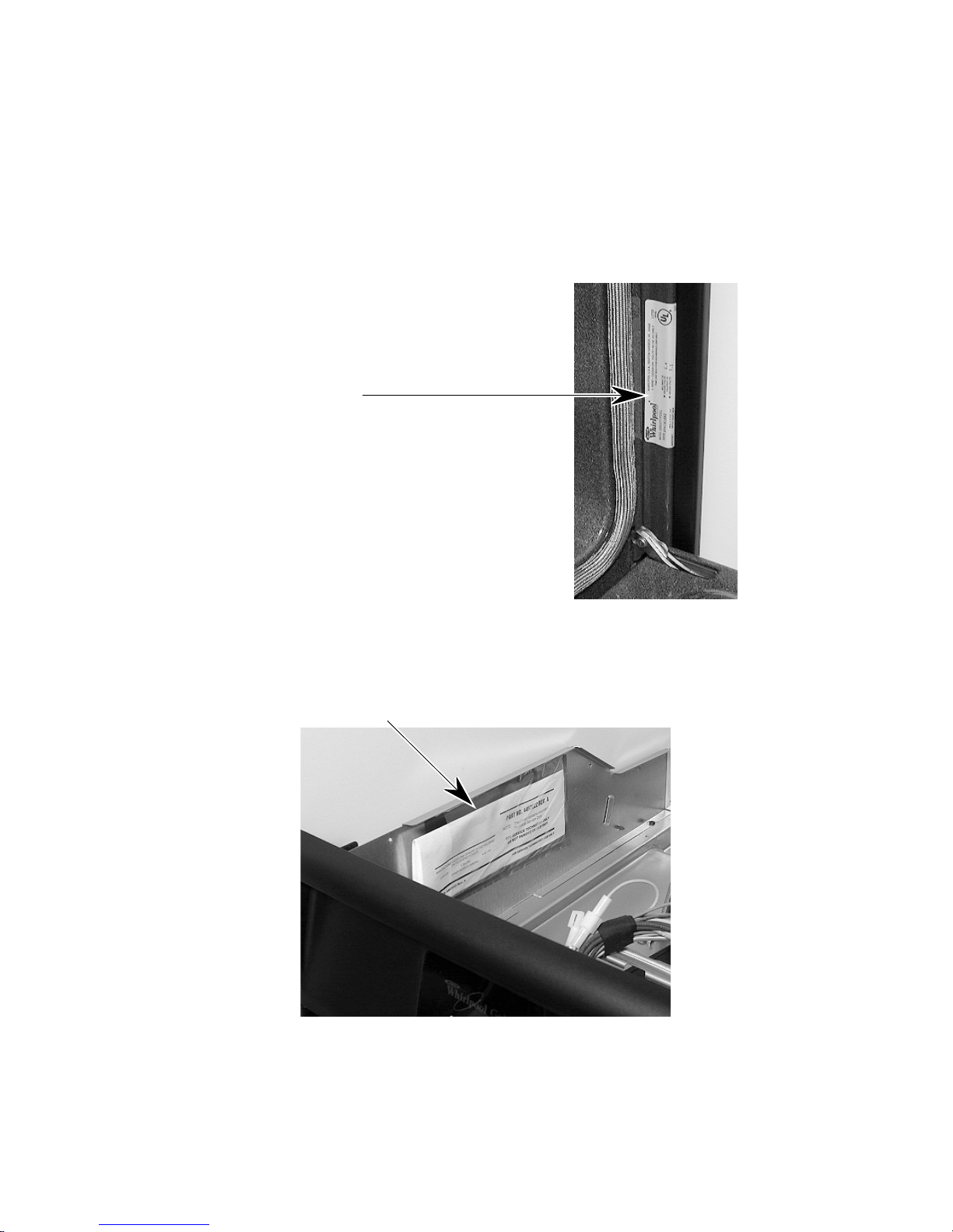
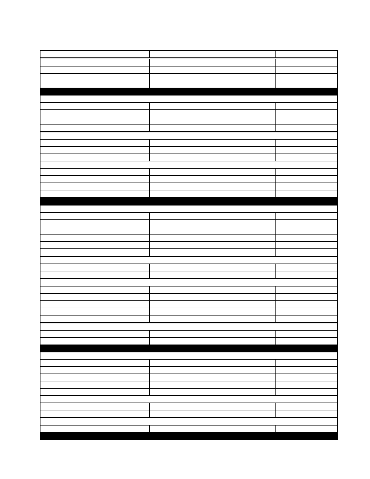
The Model/Serial Number label and Tech Sheet locations are shown below.
Model & Serial Number Location
Upper Oven
Tech Sheet Location
(Below Top Front Cover)
- vi -

IMPORTANT SAFETY INFORMATION
Your safety and the safety of others is very important.
Important safety messages have been provided in this Job Aid. Always read and obey all
safety messages.
This is the safety alert symbol.
This symbol alerts you to hazards that can kill or hurt you and others.
All safety messages will be preceded by the safety alert symbol and the word
“WARNING.”
All safety messages will identify the hazard, tell you how to reduce the chance of injury, and tell
you what can happen if the instructions are not followed.
IMPORTANT
Electrostatic Discharge (ESD)
Sensitive Electronics
ESD problems are present everywhere. ESD may damage or weaken the electronic control assembly. The new control assembly may appear to work well after repair is finished,
but failure may occur at a later date due to ESD stress.
• Use an anti-static wrist strap. Connect the wrist strap to the green ground connection
point, or to an unpainted metal surface in the appliance.
- OR -
Touch your finger repeatedly to a green ground connection point, or to an unpainted
metal surface in the appliance.
• Before removing the part from its package, touch the anti-static bag to a green ground
connection point, or to an unpainted metal surface in the appliance.
• Avoid touching electronic parts, or terminal contacts. Handle the electronic control
assembly by the edges only.
• When repackaging the failed electronic control assembly in an anti-static bag, observe
the previous instructions.
- vii -

— NOTES —
- viii -
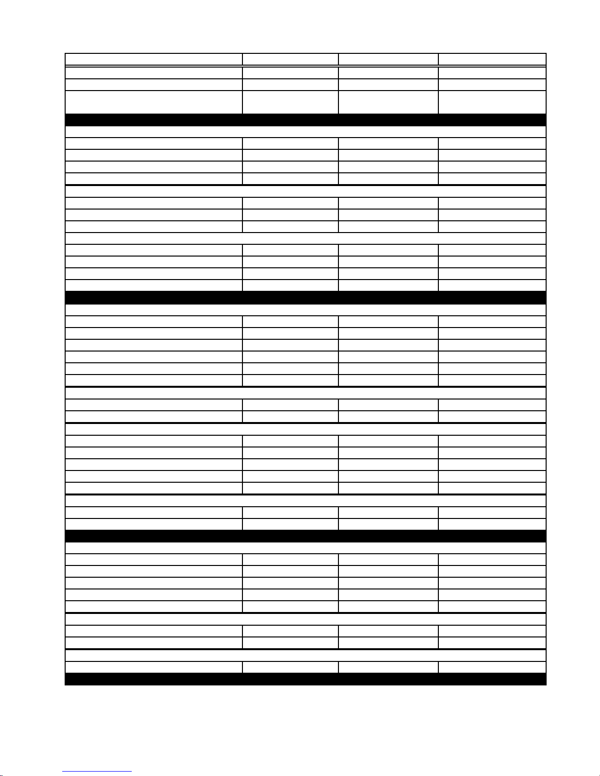
SPECIFICATIONS
Model Number
Model Description
Size-Configuration 30 " 27 " 2 4"
Color Available Biscuit, Stainless Stainless
Dimensions/Specifications
Exterior Dimensions
Overall Height (in) 51 1/8" 51 1/8" 51 1/8"
Overall Width (in) 29 3/4" 26 3/4" 23 3/4"
Overall Depth Inc Hrdwr/Hndl (in) 25 1/8" 25 1/8" 25 1/8"
Depth W/O Handle (in)
Cutout Dimensions
Cutout Height (in) (Measure Or Min/Max) 49 3/4" 49 3/4" 49 3/4"
Cutout Width (in) (Measure Or Min/Max) 28 1/2" 25 1/2" 22 1/2"
Cutout Depth (in) (Measure Or Min/Max) 23 1/4" 23 1/4" 23 1/4"
Total Connected Load (In KW)
240 Volts 7.2 7.2 9.7
208 Volts 5.4 5. 4 7.3
Circuit Amps 4 0 4 0 4 0
Oven Control Type
Interior
Main/Single Oven
Main Cleaning System Self Cleaning Self Cleaning Self Cleaning
Main Self Clean Latch Yes Yes Yes
Main Oven Liner Finish Porcelain Porcelain Porcelain
Main Oven Height (in) 16 " 16" 16"
Main Oven Width (in) 2 5 " 2 2 " 19"
Main Oven Depth (in)
Electric Element Output
Bake (W@240/208V) 2000 W/ 1500 W 2000 W/ 1500 W 2000 W/ 1500 W
Broil (W@240/208V)
Lower/Secondary Oven
Lower/Secondary Cleaning System Self Cleaning Self Cleaning Standard
Lower/Secondary Auto Self Clean Latch Yes Yes No
Lower/Secondary Oven Height (in) 16" 16 " 16"
Lower/Secondary Oven Width (in) 2 5" 2 2 " 19"
Lower/Secondary Oven Depth (in)
Lower/Secondary Electric Element Output
Lower/Secondary Bake (w@240/208v) 2000 W/ 1500 W 2000 W/ 1500 W 2000 W/ 1500 W
Lower/Secondary Broil (w@240/208v) 3000 W/ 2250 W 3000 W/ 2250 W 3000 W/ 2250 W
Miscellaneous
Product Literature
Cookbook Part/Comment 4449237 4449237 N/A
Installation Instructions Part/Comment 4450411 4450410 4448969
Service Manual Part/Comment 8178007 8178007 8178007
Tech Sheet Part/Comment 4451887 4451887 4451887
Use & Care Guide Oven Part/Comment 4450569 4450569 4448976
Other
Agency Approvals UL UL UL, CSA
Residential Use Only
Warranty
Full (Months) 12 12 12
GBD307PD GBD277PD RBD245PD
Double Built-In Oven Double Built-In Oven Double Built-In Oven
Biscuit, White-On-White,
Black
23 7/8" 23 7/8" 23 7/8"
Electronic Electronic Electronic
18 1/2" 18 1/2" 18 1/2"
3000 W/ 2250 W 3000 W/ 2250 W 3000 W/ 2250 W
18 1/2" 18 1/2" 18 1/2"
Yes Yes Yes
1-1

Model Number
Model Description
Size-Configuration 27 " 27 " 27 "
Dimensions/Specifications
Exterior Dimensions
Overall Height (in) 51 1/8" 51 1/8" 51 1/8"
Overall Width (in) 26 3/4" 26 3/4" 26 3/4"
Overall Depth Inc Hrdwr/Hndl (in) 25 1/8" 25 1/8" 25 1/8"
Depth W/O Handle (in)
Cutout Dimensions
Cutout Height (in) (Measure Or Min/Max) 49 3/4" 49 3/4" 49 3/4"
Cutout Width (in) (Measure Or Min/Max) 25 1/2" 25 1/2" 25 1/2"
Cutout Depth (in) (Measure Or Min/Max) 23 1/4" 23 1/4" 23 1/4"
Total Connected Load (In KW)
240 Volts 9.7 9.7 9.7
208 Volts 7.3 7.3 7.3
Circuit Amps 4 0 4 0 4 0
Oven Control Type
Interior
Main/Single Oven
Main Cleaning System Self Cleaning Self Cleaning Self Cleaning
Main Self Clean Latch Yes Yes Yes
Main Oven Liner Finish Porcelain Porcelain Porcelain
Main Oven Height (in) 16 " 16" 16"
Main Oven Width (in) 2 2 " 2 2" 2 2 "
Main Oven Depth (in)
Electric Element Output
Bake (W@240/208V) 2000 W/ 1500 W 2000 W/ 1500 W 2000 W/ 1500 W
Broil (W@240/208V)
Lower/Secondary Oven
Lower/Secondary Cleaning System Standard Self Cleaning Self Cleaning
Lower/Secondary Auto Self Clean Latch No Yes Yes
Lower/Secondary Oven Height (in) 16" 16" 16"
Lower/Secondary Oven Width (in) 19" 19" 22 "
Lower/Secondary Oven Depth (in)
Lower/Secondary Electric Element Output
Lower/Secondary Bake (w@240/208v) 2000 W/ 1500 W 2000 W/ 1500 W 2000 W/ 1500 W
Lower/Secondary Broil (w@240/208v) 3000 W/ 2250 W 3000 W/ 2250 W 3000 W/ 2250 W
Miscellaneous
Product Literature
Cookbook Part/Comment N / A N / A N/ A
Installation Instructions Part/Comment 4448970 4448970 4448969
Service Manual Part/Comment 8178007 8178007 8178007
Tech Sheet Part/Comment 4451887 4451887 4451887
Use & Care Guide Oven Part/Comment
Other
Agency Approvals UL, CSA UL, CSA UL, CSA
Residential Use Only
Warranty
Full (Months) 12 12 12
RBD275PD RBD276PD RBD277PD
Double Built-In Oven Double Built-In Oven Double Built-In Oven
Biscuit, White-On-
White, Black
23 7/8" 23 7/8" 23 7/8"
Electronic Electronic Electronic
18 1/2" 18 1/2" 18 1/2"
3000 W/ 2250 W 3000 W/ 2250 W 3000 W/ 2250 W
18 1/2" 18 1/2" 18 1/2"
4448976 4448976 4448976
Yes Yes Yes
Black, White-On -White Color Available Black, White-On -White
1-2
Model Number
Model Description
Size-Configuration 30 " 30 " 30 "
Color Available
Dimensions/Specifications
Exterior Dimensions
Overall Height (in) 51 1/8" 51 1/8" 51 1/8"
Overall Width (in) 29 3/4" 29 3/4" 29 3/4"
Overall Depth Inc Hrdwr/Hndl (in) 25 1/8" 25 1/8" 25 1/8"
Depth W/O Handle (in)
Cutout Dimensions
Cutout Height (in) (Measure Or Min/Max) 49 3/4" 49 3/4" 49 3/4"
Cutout Width (in) (Measure Or Min/Max) 28 1/2" 28 1/2" 28 1/2"
Cutout Depth (in) (Measure Or Min/Max) 23 1/4" 23 1/4" 23 1/4"
Total Connected Load (In KW)
240 Volts 9.7 9.7 9.7
208 Volts 7.3 7.3 7.3
Circuit Amps 4 0 4 0 4 0
Oven Control Type
Interior
Main/Single Oven
Main Cleaning System Self Cleaning Self Cleaning Self Cleaning
Main Self Clean Latch Yes Yes Yes
Main Oven Liner Finish Porcelain Porcelain Porcelain
Main Oven Height (in) 16 " 16" 16"
Main Oven Width (in) 2 5 " 2 5 " 2 5 "
Main Oven Depth (in)
Electric Element Output
Bake (W@240/208V) 2000 W/ 1500 W 2000 W/ 1500 W 2000 W/ 1500 W
Broil (W@240/208V)
Lower/Secondary Oven
Lower/Secondary Cleaning System Standard Standard Self Cleaning
Lower/Secondary Auto Self Clean Latch No No Yes
Lower/Secondary Oven Height (in) 16" 1 6" 16"
Lower/Secondary Oven Width (in) 25 " 2 5 " 2 5 "
Lower/Secondary Oven Depth (in)
Lower/Secondary Electric Element Output
Lower/Secondary Bake (w@240/208v) 2000 W/ 1500 W 2000 W/ 1500 W 2000 W/ 1500 W
Lower/Secondary Broil (w@240/208v) 3000 W/ 2250 W 3000 W/ 2250 W 3000 W/ 2250 W
Miscellaneous
Product Literature
Cookbook Part/Comment 4449066 4449066 4449066
Installation Instructions Part/Comment 4448975 4448975 4448975
Service Manual Part/Comment 8178007 8178007 8178007
Tech Sheet Part/Comment 4451887 4451887 4451887
Use & Care Guide Oven Part/Comment
Other
Agency Approvals UL, CSA UL, CSA UL, CSA
Residential Use Only
Warranty
Full (Months) 12 12 12
RBD305PD RBD306PD RBD307PD
Double Built-In Oven Double Built-In Oven Double Built-In Oven
Biscuit, White-On-
White, Black
23 7/8" 23 7/8" 23 7/8"
Electronic Electronic Electronic
18 1/2" 18 1/2" 18 1/2"
3000 W/ 2250 W 3000 W/ 2250 W 3000 W/ 2250 W
18 1/2" 18 1/2" 18 1/2"
4448976 4448976 4448976
Yes Yes Yes
Black, Almond-On-
Almond, White-On-White
Black, Almond-On-Almond,
White-On-White
1-3

— NOTES —
1-4
INSTALLATION HIGHLIGHTS
ELECTRICAL SUPPLY REQUIREMENTS
• The oven must be connected with copper
WARNING
Electrical Shock Hazard
• An electrical ground is required on this
appliance.
• Do not use an extension cord with this
appliance.
• If a cold water pipe is interrupted by plastic, nonmetallic gaskets, or other insulating materials, do not use for grounding.
• Do not ground to a gas pipe.
• Do not use a fuse in the neutral or grounding circuit. It could result in an electrical
shock.
• Check with a qualified electrician if you are
in doubt as to whether the appliance is
properly grounded.
Failure to follow these instructions could
result in death or serious injury.
GENERAL
If codes permit, and a separate grounding wire
is used, it is recommended that a qualified electrician determine that the grounding path and
wire gauge are in accordance with local codes.
The following information applies to the builtin electric wall oven wiring:
• The oven must be connected to the proper
electrical voltage and frequency as specified
on the model/serial rating plate (located on
the upper oven frame).
wire only.
• Wire sizes and connections must conform to
the requirements of the National Electrical
Code, ANSI/NFPA 70—latest edition*, and
all local codes and ordinances. Wire sizes
and connections must conform with the rating of the appliance. Copies of the standards
listed above may be obtained from:
* National Fire Protection Association
Batterymarch Park
Quincy, Massachusetts 02269
• The oven should be connected directly to a
time delay fuse or circuit breaker through
flexible, armored, or nonmetallic sheathed,
copper cable. The flexible, armored cable
that extends from the appliance should be
connected directly to the junction box.
• Fuse both sides of the line.
• Locate the junction box to allow as much
slack as possible between the junction box
and the appliance so that the appliance can
be moved if servicing is ever necessary. Do
not cut the conduit.
• A U.L.-listed conduit connector must be provided at the junction box.
• Wiring diagrams are located in Section 7 of
this Job Aid.
• A Tech Sheet is located below the top access cover on all models.
• Models rated from 7.3 to 9.6 kW at 240-volts,
(5.5 to 7.2 kW at 208-volts), require a separate 40-ampere circuit. Models rated at 7.2
kW and below at 240-volts, (5.4 kW and
below at 208-volts), require a separate 30ampere circuit.
2-1
ELECTRICAL WIRING
WARNING
Electrical Shock Hazard
• An electrical ground is required on this
appliance.
• Do not connect to the electrical supply
until the appliance is permanently
grounded.
• Turn off power to the junction box before
making the electrical connections.
• Connect the appliance to a grounded,
metallic, permanent wiring system.
Failure to follow these instructions could
result in death or serious injury.
1. Insert the end of the flexible conduit through
the cabinet opening to the junction box
inlet.
2. Disconnect the power going to the junction box.
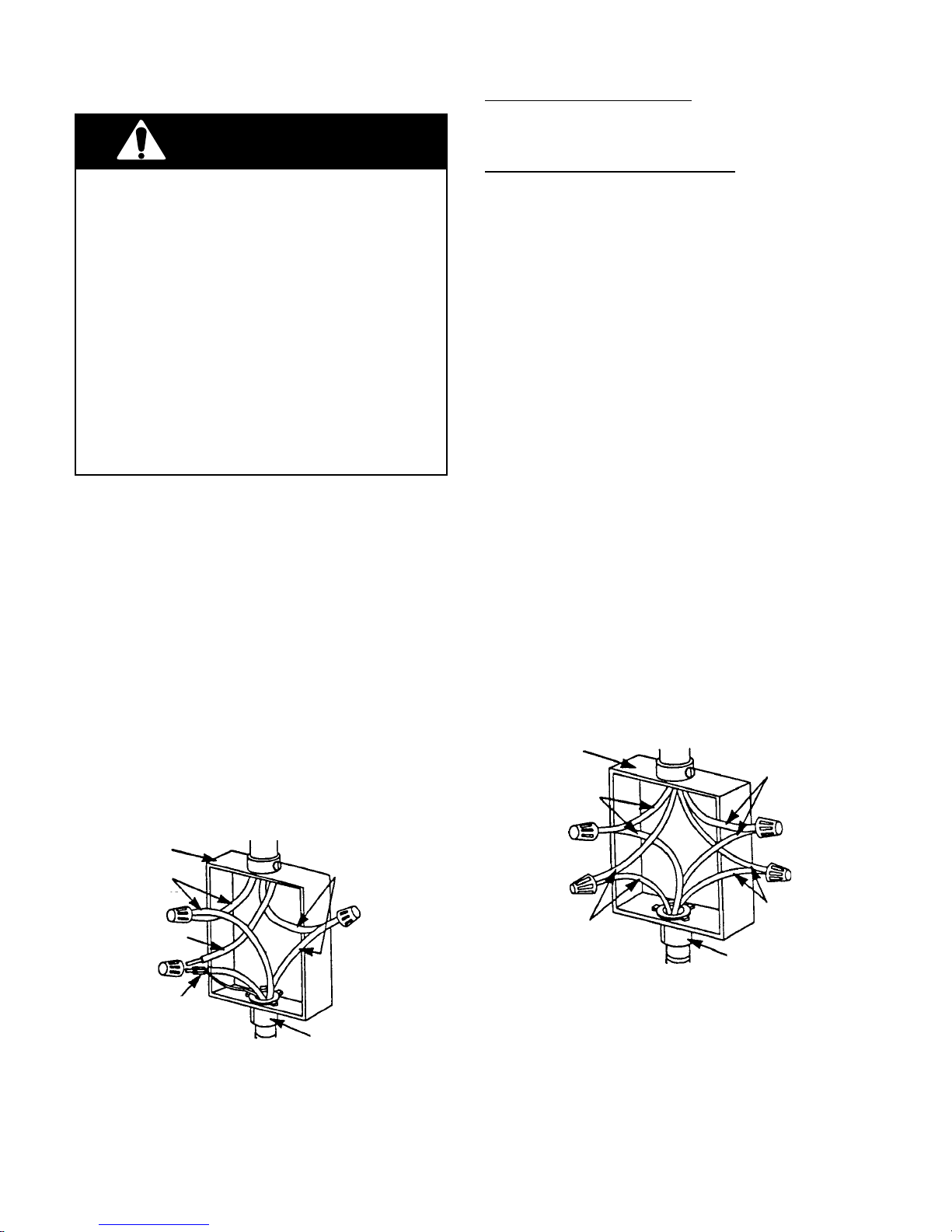
3. Open the junction box cover and connect
the flexible conduit to the U.L.-listed conduit connector.
4. Connect the ends of the black wires together with twist-on connectors (see the
illustration below).
5. Connect the ends of the red wires together
with twist-on connectors.
cable from
power supply
junction box
red wires
black wires
If local codes DO permit connecting the cabinet-grounding conductor to a neutral junction
box wire, perform steps 6 and 7.
If local codes DO NOT permit connecting the
cabinet-grounding conductor to a neutral junction box wire, or if you are connecting the
appliance to a 4-wire electrical system, perform steps 8 through 11.
6. Connect the factory-crimped bare and
white electrical wires coming from the
appliance conduit cable to the white (neutral) wire inside the junction box (see the
illustration below).
7. Replace the junction box cover.
8. Separate the factory-crimped bare and
white electrical wires coming from the
appliance conduit cable.
9. Connect the white appliance wire to the
white (neutral) wire inside the junction
box.
10. Connect the bare grounding wire from the
appliance to a grounded wire inside the
junction box. IMPORTANT: Do not con-
nect the bare grounding wire to the
white (neutral) wire in the junction box.
11. Replace the junction box cover.
cable from
power supply
junction box
white wires
red wires
white wire
white & bare
grounding
appliance wires
factory crimped cable from
oven
Crimped Grounding Conductors
To White (Neutral) Wire
U.L.-listed
connector
conduit
2-2
bare
grounding
appliance wires
cable from
oven
Separate Grounding Conductors
To White (Neutral) & Bare Wires
U.L.-listed
conduit
connector
black wires
REMOVING & REINSTALLING THE OVEN DOOR
WARNING
Personal Injury Hazard
• Use both hands to remove oven doors.
• Do not use the handle or any portion of the
front frame or trim for lifting.
• Because of the weight and size of the
oven, two or more people are required to
move and safely install it.
Failure to properly grasp the oven doors or to
lift the oven properly could result in personal
injury or damage to the product.
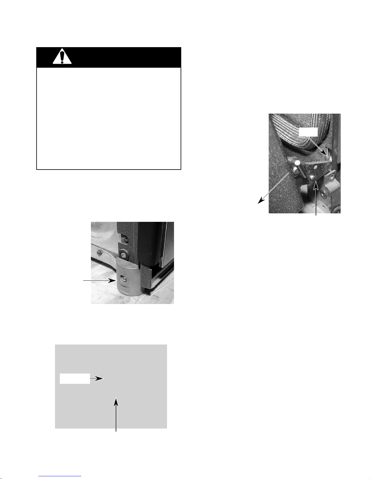
CAUTION: Do not remove the shipping base
or the shipping feet at the front lower corners of the oven. The shipping feet will
protect the lower oven trim until the oven is
inserted into the cabinet cutout.
2. Close the oven door as far as the two pins
will allow.
3. Grasp the sides of the door and lift the door
until it stops, then pull the hinge hangers
out of the slots.
Slot
Hinge Hanger
Shipping Foot
To remove the oven door:
1. Install a pin in the hole of each oven door
hinge hanger.
Door Pin
To reinstall the oven door:
1. Grasp the sides of the door and tilt it back
at a slight angle, then insert the hinge
hangers into the hinge slots as far as they
will go.
2. Rotate the top of the door towards the
oven so the hinge hangers fit onto the
support pins.
3. Close the oven door as far as the pins will
allow, and make sure that the hinge hangers are fully seated on the support pins. If
they are not seated properly, the door will
not close tightly and may be off-center. To
seat the hinge hangers, open the door
slightly, and push in on the bottom until the
hangers are fully seated.
4. Open the oven door to its fully open position and remove the two hinge hanger
pins.
5. Close the oven door completely and check
it for proper operation and alignment.
Door Pin Into Hinge Hanger Hole
2-3

— NOTES —
2-4
PRODUCT OPERATION
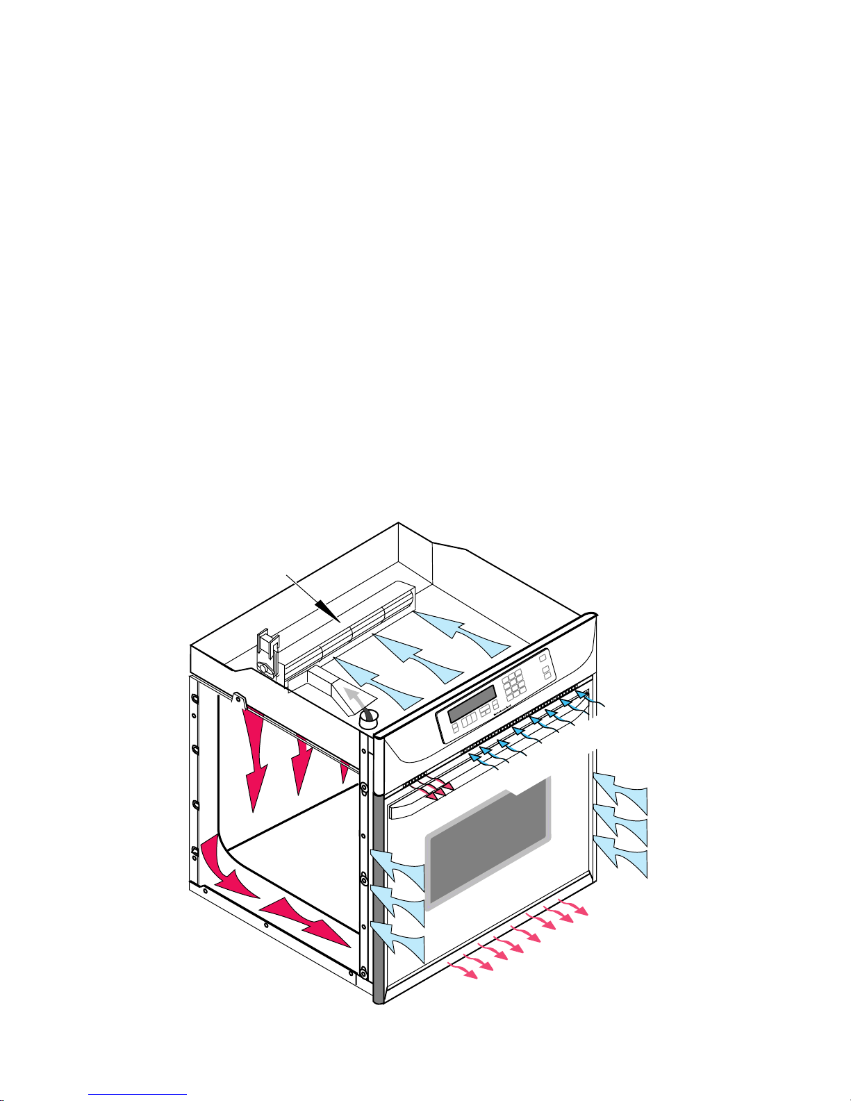
AIR FLOW
Intake air is drawn into the oven at two locations: through the control panel vent, (over the
latch assembly and the inner chassis top), and
through the side mounting rails (over the oven
sides and around the back). Air also enters the
oven at the back through the openings on the
upper section of the rear cover. At this point,
the air from the sides and the top mix. The air
is then pulled through the blower, down the
back of the unit between the outer and inner
rear covers, and out the front of the unit via the
bottom vent trim.
Air from the blower is forced over the cavity
vent. The pressure differential causes air to be
drawn from the cavity, where the air exits
through a small opening on the left side of the
control panel vent.
Air passes through the oven door by a combination of natural and forced convection. Air
enters the door through the bottom slots, and
passes between the outer glass, and the angled
inner glass. This air exits through the top slots
in the door via natural convection. Air also
enters the bottom of the door, and is drawn
between the two pieces of inner door glass,
where it exits through the top slots in the upper
part of the door. This air is then drawn into the
blower, and is forced down the back of the unit
between the inner and outer chassis covers,
and finally out the bottom vent.
The purpose of the convection fan is to circulate hot air inside the oven cavity, not to evacuate the air. Thus, the air flow for the convection
models and the non-convection models, is the
same.
BLOWER
INTAKE AIR
EXHAUST AIR
INTAKE AIR
OVEN
EXHAUST AIR
3-1
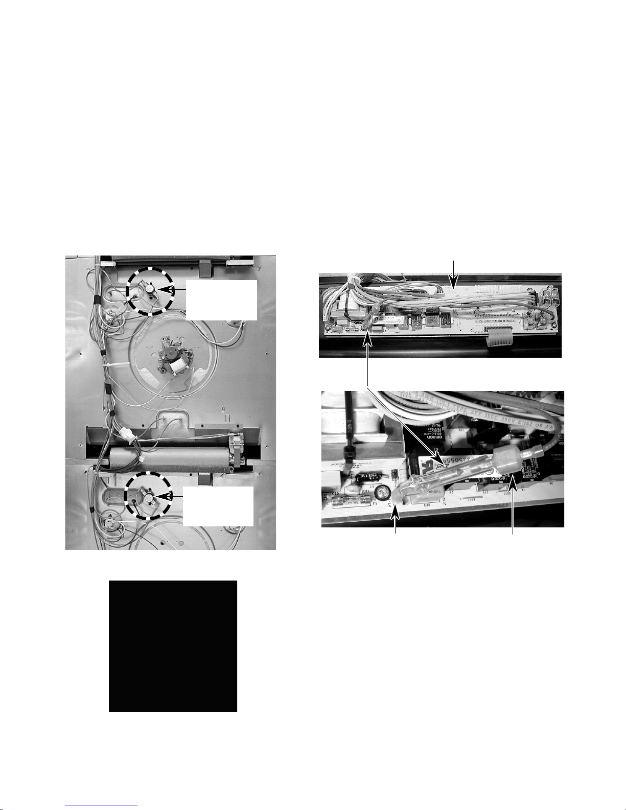
THE OVEN SHUTDOWN THERMAL FUSE
& CONTROL PANEL THERMAL FUSE
There are two thermal fuses on the oven. The
thermal fuses operate as follows:
• Upper & Lower Oven Shutdown Ther-
mal Fuse — These thermal fuses are
located on the rear of the oven at the indicated locations. Each oven shutdown
thermal fuse opens L2 to the oven if the
temperature at the rear panel exceeds
160˚C/320˚F. The two fuses are onetime, non-resettable safety devices.
Upper Oven
Shutdown
Thermal Fuse
• Control Panel Thermal Fuse — Protects the control panel area if the temperature exceeds 101˚C/214˚F. If the
fuse opens, it shuts down the entire unit
(no clock, etc.). One end of the thermal
fuse is connected to the control panel
at lug P7-1, and the other end is connected to the main wire harness. The
thermal fuse is a one-time, nonresettable fuse.
Control Panel
Thermal Fuse
Lower Oven
Shutdown
Thermal Fuse
BACK OF OVEN
Oven Shutdown Thermal Fuse
3-2
Connector P7-1
Connector To Wire
Harness
 Loading...