

Page 1
DOUBLE
PLEASE NOTE: Y
clearer instruction.
our model of DishDrawer may differ from the model shown in the diagrams. Diagrams have been simpliÞ ed to enable
INTEGRATED PANEL PREPARATION
FOLLOW THESE INSTRUCTIONS BEFORE REFERRING TO PRODUCT INSTALLATION INSTRUCTION SHEET P/N 526609.
P/N 526610A
DOUBLE MODELS ONLY
(page 1 of 4)
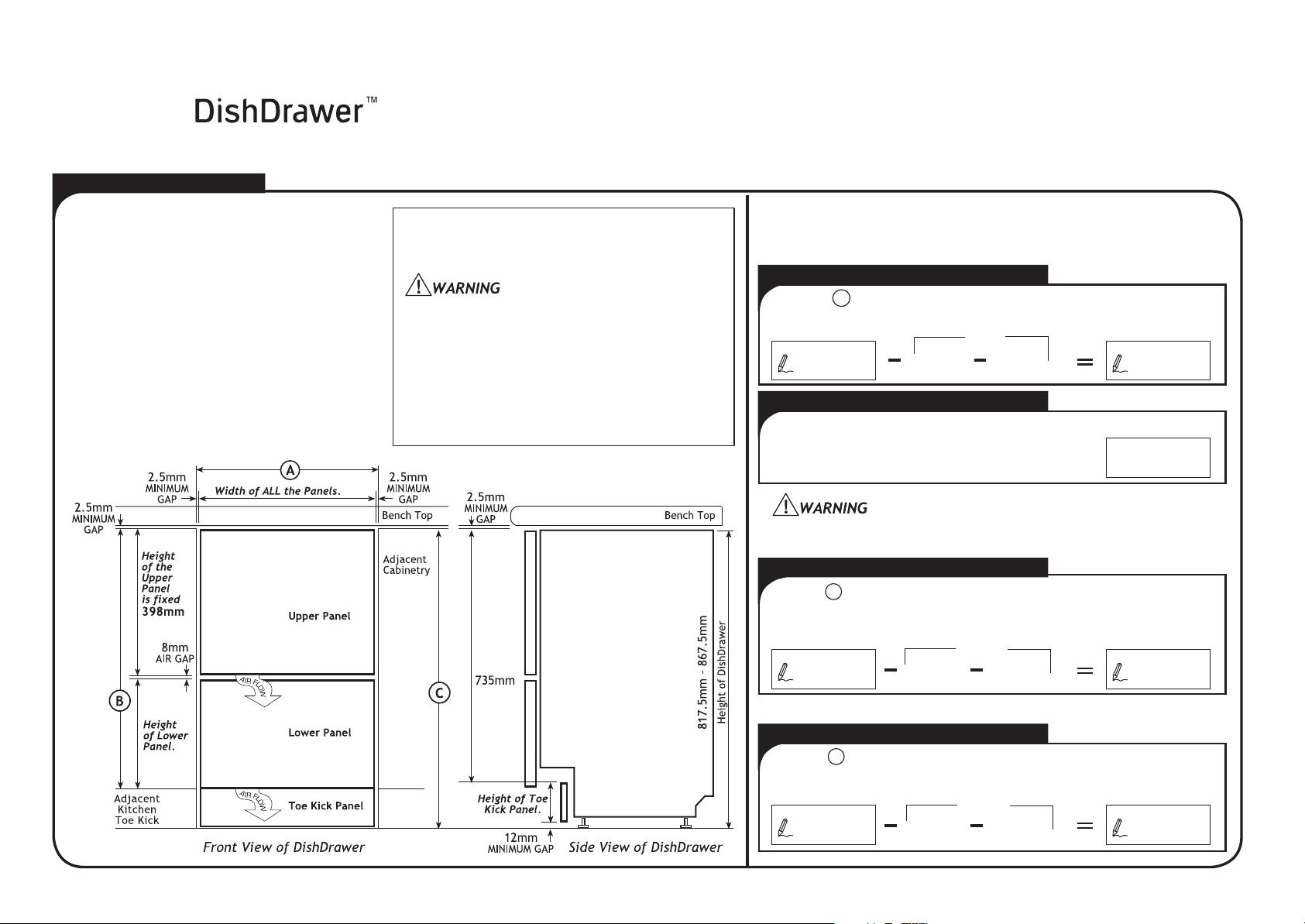
BEFORE
The Doors and T
DishDrawer can match your kitchen cabinetry.
The diagram below, with the addition of your
own measurements will help you calculate the
width of all the Panels, the height of the
Lower P
Panel.
is FIXED at 398mm.
TOE KICK PANEL
The T
Panel thickness.
Toe Kick
the Integrated Toe Kick Panel.
YOU START
oe Kick Panels of the
anel and the height of the Toe Kick
NOTE: The height of the Upper Panel
DEPTH
oe Kick Panel Depth is 67mm less the
NOTE: The Black PreÞ nished
supplied is an alternative to making
INTEGRATED PANEL MATERIAL
Upper & Lower Panel Thickness 16mm minimum.
Above 18mm Product depth will be affected.
Toe Kick Panel Thickness 9-19mm
Drawer Front material must be suitable for damp
conditions or adequately sealed to withstand
moisture. Additional protection can be provided
by using a “Moisture Resistant Board”.
Ensure the Product is not plugged in.
The installation of the Panels requires an
electrical connection and must be performed by
a suitably qualiÞ ed person.
The size of each Panel can be calculated below.
Write the required measurement in the Þ rst box and
then subtract the following dimensions in each equation.
WIDTH OF ALL PANELS
Measure the width of the cavity, and
A
put the dimension here.
5mm
2.5mm 2.5mm
MIN. GAP MIN. GAP
Width of
(Minimum
ALL Panels
HEIGHT OF UPPER PANEL
Height of Upper Panel
The height of the Upper Panel is Þ xed.
The air vent between the Upper and Lower Panels must not be
covered. An air gap of 8mm MUST be provided.
398mm
HEIGHT OF LOWER PANEL
Measure from the top of the adjacent cabinet
door to the top of the adjacent kitchen Toe
Kick, and put the dimension here.
B
406mm
398mm 8mm
AIR GAP
Height of
Lower Panel
(Minimum
595mm)
308mm)
HEIGHT OF TOE KICK PANEL
Measure the height from the adjacent cabinet
door fronts to the fl oor, and put the dimension
here.
C
747mm
735mm 12mm
MIN. GAP
Height of
Toe Kick Panel
(Minimum 70.5mm)
Page 2
P/N 526610A (page 2 of 4)
DOUBLE MODELS ONLY
Safety Glasses, Tape Measure, Pencil, Needle-Nose Pliers,
Drill & Phillips Bit or Phillips Screwdriver,
25mm Spade Bit or 25mm Hole Saw,
Small Hand or Jig Saw.
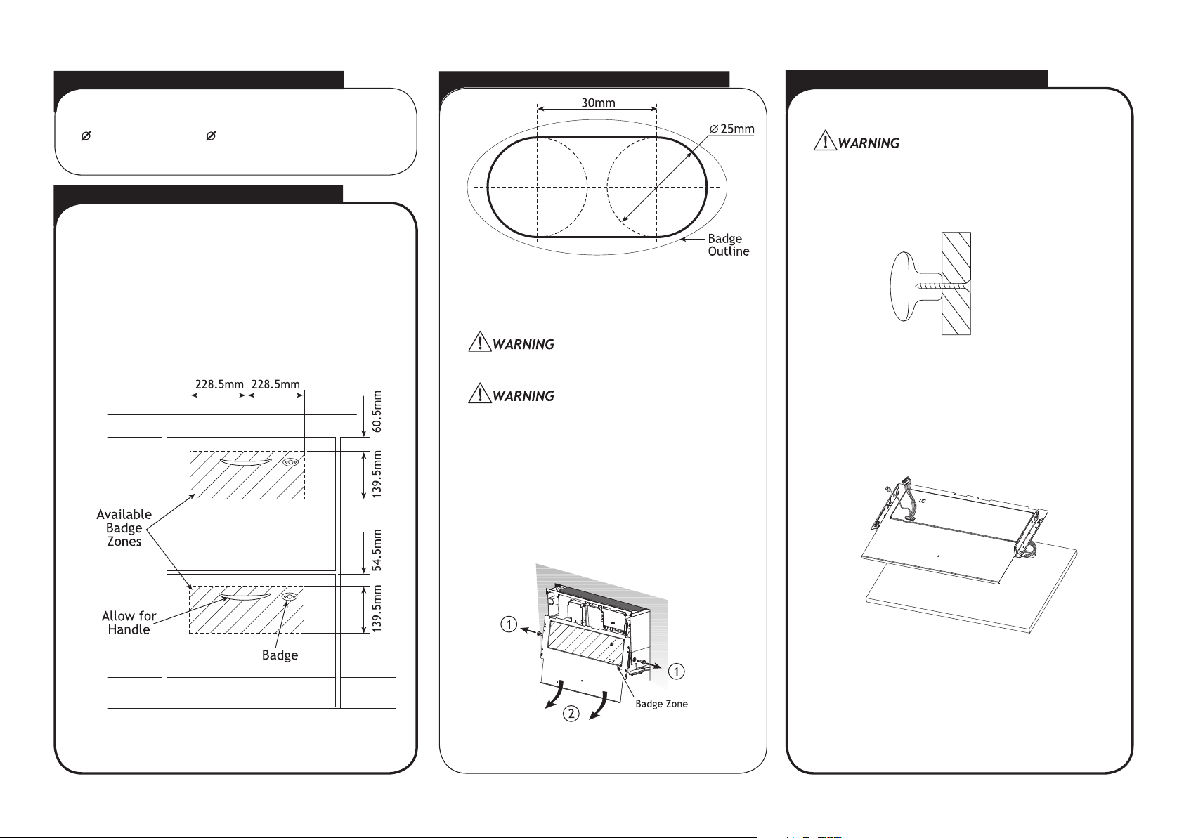
1 BADGE & HANDLE POSITION
On both Panels, select the Badge position to suit the
cabinetry design, within the available badge zones.
If required the Badge may be centred on the edge of
the badge zone.
The handle position will also need to be taken into
account.
2 BADGE CUT OUT & BRACKET REMOVAL TOOLS NEEDED
(Badge cut out shown actual size)
Cut the badge slot in each Panel by drilling
two 25mm diameter holes and cutting out the
remaining material between the holes.
Accuracy is essential when cutting the Badge
slot to ensure a neat Þ t to hold the Badge.
Ensure the Product is not plugged in.
To remove the Mounting Brackets withdraw the
pins from the drawer sides, using a pair of
needle-nose pliers.
3 FITTING THE HANDLE & BADGE
Fit the customer supplied handle.
When mounting the handle, ensure
fastenings do not protrude beyond the
back surface of the Panel.
Fit a Badge to each Panel by feeding the wires
through to the back and pressing the Badge
into the cut out.
If needed adhere the Badge to the Panel with
an adhesive.
Gently slide the Mounting Bracket off in a
downwards and outwards motion. Disconnect
the Mounting Bracket and Badge earthing wires,
along with the Badge harness. Remove the
Badge from the Mounting Bracket.
NOTE: The rectangular recess in the Mounting
Bracket can also be used to deÞ ne the badge
zone.
Page 3
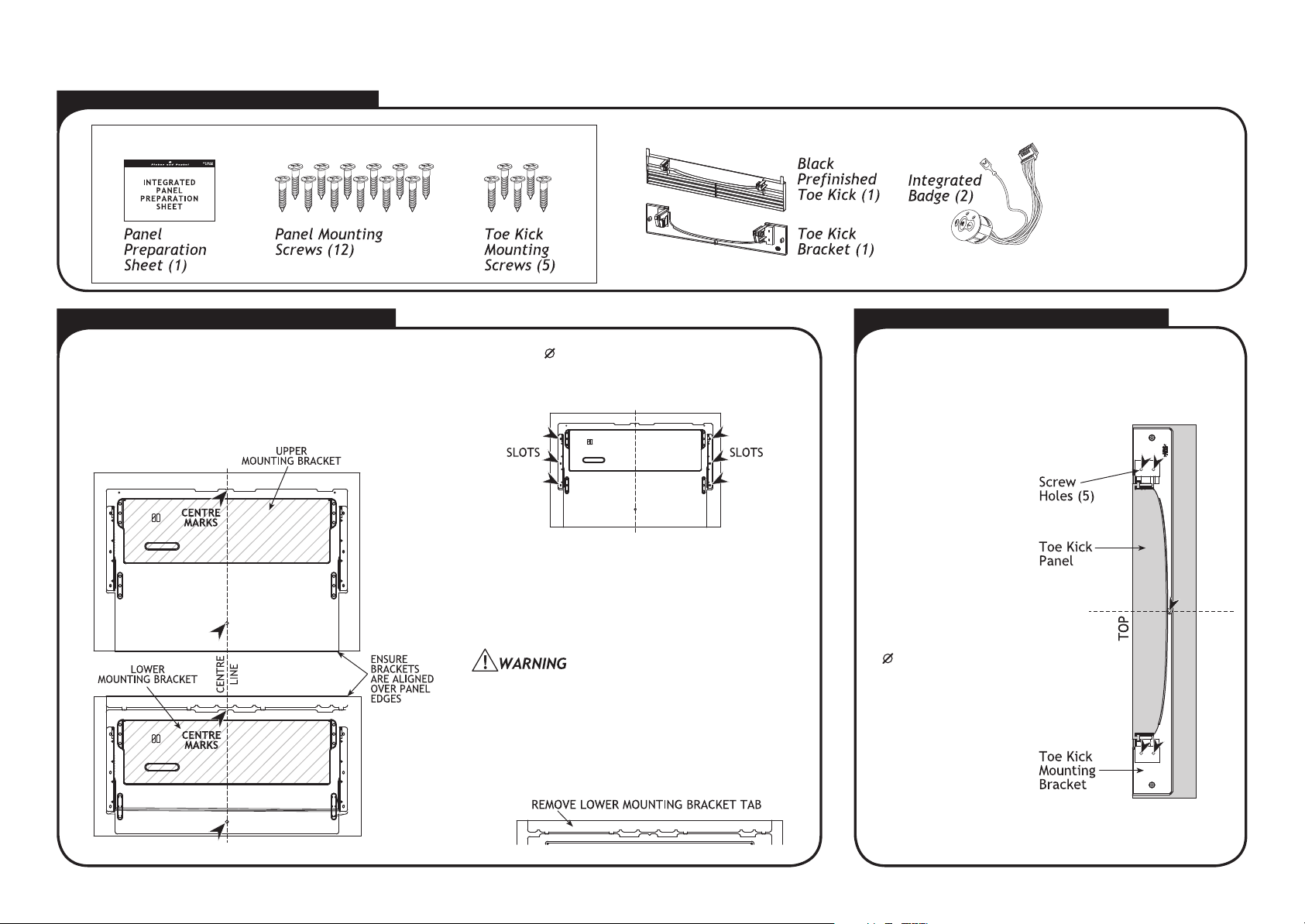
PARTS LIST FOR DOUBLE MODELS
P/N 526610A (page 3 of 4)
DOUBLE MODELS ONLY
INTEGRATED PARTS KIT P/N 526675
4 SECURING THE MOUNTING BRACKETS
Each Mounting Bracket is directly screwed to the
back of each Integrated Panel. On a soft surface
centralise and align the Upper Mounting Bracket on
the Upper Panel and the Lower Mounting Bracket on
the Lower Panel.
Using the 6 4mm x 16mm screws supplied, secure
the Mounting Bracket to each Panel at the 6 points
shown in the diagram.
NOTE: The Mounting Brackets need to be securely
Þ xed to each Panel. Where possible use the 6 outer
slots shown above. If these slots can not be used,
select alternative slots, as close as possible to the
outer slots. Ensure the screws are evenly spaced
about the Panel.
For some materials pilot holes may need to be
drilled Þ rst before screwing the Mounting Bracket
onto the Panel. Ensure the drill does not damage
the face of the Panel.
IMPORTANT
Break off the tab at the top of the Lower
Mounting Bracket, after Panel has been
secured.
P/N 526681
P/N 526682
5 SECURING THE TOE KICK PANEL
Chrome supplied
P/N 526618
OTHER COLOURS
AVAILABLE
Black Kit P/N 526683
Satin Chrome Kit P/N 526684
Brass Kit P/N 526685
NOTE: If using the supplied Black PreÞ nished Toe
Kick, proceed to Step 6 Earthing the Mounting
Brackets and Connecting the Badge Wires.
Place Toe Kick
Panel face down
on a soft surface
and mark a vertical
centre line.
Centralise the
plastic Mounting
Bracket on top of
the Toe Kick Panel.
Align the top of the
Bracket with the
top of the Panel.
Using the 5
4mm x 16mm
screws provided Þ x
the Mounting
Bracket to the Toe
Kick Panel.
Page 4

P/N 526610A (page 4 of 4)
DOUBLE MODELS ONLY
6 EARTHING THE MOUNTING BRACKETS & CONNECTING THE BADGE WIRES 7 FITTING THE PANELS TO THE PRODUCT
Ensure the Product is not plugged in.
The Badge Isolator Board is an electrostatic
sensitive device. Ensure you are adequately
earthed when connecting or disconnecting the
Badge by wearing an earthing strap or by
earthing yourself to the DishDrawer.
Partially open the drawer. Fit the assembled Panels
by sliding in an inwards and upwards motion. The
rubber seal between the Drawer and Panels must
be kept in place.
Plug the green
Badge earthing
wire onto a
Mounting Bracket
tab. Plug the
earthing wire from
the Product onto
the other Mounting
Bracket tab.
Secure the Panels by inserting the
pins on either side of the Drawer.
Ensure that the rib on the pin is
vertical.
Check the Þ t of the Panels, making sure the air
ß ow gap is 8mm between the Upper and Lower
Panels.
NOTE: Do not Þ t the Toe Kick Panel
(or supplied Black PreÞ nished Toe Kick)
to the DishDrawer until the Product is in the
cavity.
Connect the Badge
plug to the top of the
Badge Isolator Box.
INTEGRATED PANEL PREPARATION IS COMPLETE.
The Product is now ready to install. Refer to
Product Installation Instruction Sheet P/N 526609.
Page 5

INTEGRATED PANEL PREPARATION SINGLE
PLEASE NOTE: Your model of DishDrawer may differ from the model shown in the diagrams. Diagrams have been simpliÞ ed to enable
clearer instruction. FOLLOW THESE INSTRUCTIONS BEFORE REFERRING TO PRODUCT INSTALLATION INSTRUCTION SHEET P/N 526609.
BEFORE YOU START
P/N 526610A (page 1 of 4)
SINGLE MODELS ONLY
The Door of the DishDrawer
can match your kitchen
cabinetry. The diagram
below, with the addition of
your own measurements will
help you calculate the width
and height of the Panel.
Ensure the Product is not
plugged in.
The installation of the Panel
requires an electrical
connection and must be
performed by a suitably
qualif ed person.
Use the following diagram if installing the DishDrawer at ß oor
level.
The size of each Panel can be calculated below.
Write the required measurement in the Þ rst box and
then subtract the following dimensions in each equation.
WIDTH OF THE PANEL
Measure the width of the cavity, and
A
put the dimension here.
5mm
2.5mm 2.5mm
MIN. GAP MIN. GAP
The air vent below the Panel must not be covered.
An air gap of 9mm MUST be provided.
Width of the Panel
(Minimum 595mm)
HEIGHT OF THE PANEL
Measure the height of adjacent
cabinet door fronts in kitchen, and put
the dimension here.
INTEGRATED PANEL MATERIAL
Upper & Lower Panel Thickness 16mm minimum.
Above 18mm Product depth will be affected.
B
(Minimum 398mm)
9mm
AIR GAP
Height of
the Panel
Drawer Front material must be suitable for damp conditions or
adequately sealed to withstand moisture. Additional protection
can be provided by using a “Moisture Resistant Board”.
Page 6

P/N 526610A (page 2 of 4)
SINGLE MODELS ONLY
Safety Glasses, Tape Measure, Pencil,
Needle-Nose Pliers, Drill & Phillips Bit or
Phillips Screwdriver,
or 25mm Hole Saw, Small Hand or Jig Saw.
25mm Spade Bit
1 BADGE & HANDLE POSITION
On the Panel, select the Badge position to suit the
cabinetry design, within the available badge zone.
If required the Badge may be centred on the edge of
the badge zone.
The handle position will also need to be taken into
account.
2 BADGE CUT OUT & BRACKET REMOVAL TOOLS NEEDED
(Badge cut out shown actual size)
Cut the badge slot in the Panel by drilling
two 25mm diameter holes and cutting out the
remaining material between the holes.
Accuracy is essential when cutting the Badge
slot to ensure a neat Þ t to hold the Badge.
Ensure the Product is not plugged in.
To remove the Mounting Bracket withdraw the
pins from the drawer sides, using a pair of
needle-nose pliers.
3 FITTING THE HANDLE & BADGE
Fit the customer supplied handle.
When mounting the handle, ensure fastenings
do not protrude beyond the back surface of the
Panel.
Fit the Badge to the Panel by feeding the wires
through to the back and pressing the Badge into
the cut out.
If needed adhere the Badge to the Panel with an
adhesive.
Gently slide the Mounting Bracket off in a
downwards and outwards motion. Disconnect
the Mounting Bracket and Badge earthing wires,
along with the Badge harness. Remove the
Badge from the Mounting Bracket.
NOTE: The rectangular recess in the Mounting
Bracket can also be used to deÞ ne the badge
zone.
Page 7

P/N 526610A (page 3 of 4)
SINGLE MODELS ONLY
PARTS LIST FOR SINGLE MODELS
INTEGRATED PARTS KIT P/N 526675P/N 526675
4 SECURING THE MOUNTING BRACKET
The Mounting Bracket is directly screwed to the
back of the Integrated Panel. On a soft surface
centralise and align the Mounting Bracket on the
Panel.
Chrome supplied
P/N 526618
OTHER COLOURS AVAILABLE
Black Kit P/N 526683
Satin Chrome Kit P/N 526684
Brass Kit P/N 526685
Using the 6
4mm x 16mm screws supplied, secure
the Mounting Bracket to the Panel at the 6 points
shown in the diagram.
5 EARTHING THE MOUNTING BRACKET
Ensure the Product is not plugged in.
NOTE: The Mounting Bracket needs to be securely
Þ xed to the Panel. Where possible use the 6 outer
slots shown above. If these slots can not be used,
select alternative slots, as close as possible to the
outer slots. Ensure the screws are evenly spaced
about the Panel.
For some materials pilot holes may need to be
drilled Þ rst before screwing the Mounting Bracket
onto the Panel. Ensure the drill does not damage
the face of the Panel.
Plug the green
Badge earthing
wire onto a
Mounting Bracket
tab. Plug the
earthing wire from
the Product onto
the other Mounting
Bracket tab.
Page 8

6 CONNECTING THE BADGE WIRES 7 FITTING THE PANEL TO THE PRODUCT
Ensure the Product is not plugged in.
The Badge Isolator Board is an electrostatic
sensitive device. Ensure you are adequately
earthed when connecting or disconnecting the
Badge by wearing a earthing strap or by
earthing yourself to the DishDrawer.
P/N 526610A (page 4 of 4)
SINGLE MODELS ONLY
Connect the Badge
plug to the top of the
Badge Isolator Box.
Partially open the drawer. Fit the assembled
Panel by sliding in an inwards and upwards
motion. The rubber seal between the Drawer
and Panel must be kept in place.
Secure the Panel by inserting the
pins on either side of the Drawer.
Ensure that the rib on the pin is
vertical.
Check the Þ t of the Panel, making sure the
air ß ow gap is 9mm between the Panel and
cabinetry.
INTEGRATED PANEL PREPARATION IS COMPLETE.
The Product is now ready to install. Refer to
Product Installation Instruction Sheet P/N 526609.
 Loading...