

Page 1
41833074.fm Page 7 Monday, December 12, 2005 4:31 PM
GB
INSTALLATION - ASSEMBLY INSTRUCTIONS
Respect the following minimum distances from the cooktop: 50 cm (electric cookers), 65 cm (gas cookers). If the
installation instructions for the gas cooker specify a greater distance, this must be taken into account. The fume
hose and hose clamps are not supplied. We recommend that you contact a qualified engineer to have the hood
installed.
Preliminary information for installing the hood:
Expansion plugs are provided to secure the hood to most types of ceilings. A qualified technician is needed, however, to make
sure that the plugs are suitable for your ceiling. The ceiling must be strong enough to take the weight of the hood.
Disconnect the power supply at the home main switch during electrical connections.
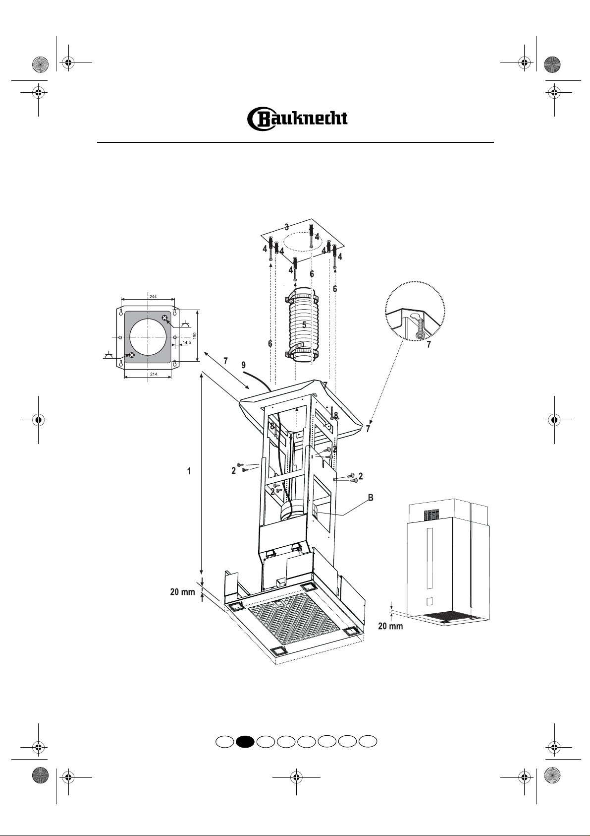
Adjust extension of the hood support structure, as the final height of the hood depends on this, and remember that with
1.
installation completed the hood must be at least 50 cm above the hob in case of electric cookers and 65 cm in case of
gas or mixed cookers.
Fix the two sections of the structure using 8 screws.
2.
Place the ceiling hole diagram directly above the cooktop (the centre of the diagram must match the centre of the
3.
cooktop and the edges must be parallel to the sides of the cooktop - the side of the diagram with the wording FRONT
corresponds to the control panel side). Prepare the electrical connection.
Drill as shown (6 holes for 6 wall plugs - 4 plugs for hooking), screw the 4 outer screws leaving a space of about 1 cm
4.
between the screw head and the ceiling.
Fit an exhaust pipe inside the truss and connect it to the collar of the motor compartment (exhaust pipe and clamps are
5.
not provided).
Hook the truss to the 4 screws (see step 4).
6.
CAUTION! The side of the truss with connection box corresponds to the side of the control panel with hood assembled.
Tighten the 4 screws.
7.
Insert and tighten another 2 screws in the remaining free holes for secure fixing.
8.
Carry out the electrical connection to the mains power supply, only turn on the power supply with assembly completed.
9.
Extractor Version:
the top of the hood.
Caution!
The discharge air must not be ducted to a flue used for removing fumes produced by appliances using gas or other fuels, but
must have a separate outlet. All national regulations governing extraction of fumes must be observed.
10.
Filter Hood
Caution!
For filter operation (
exhaust pipe to the collar located on the deflector.
11.
12.
13.
14.
15.
16.
17.
If the hood is equipped with a carbon filter, this must be removed.
For extractor operation (
If the hood is not equipped with a carbon filter, one must be ordered and fitted prior to use.
Fit the nuts with fixing hooks supplied inside the top and bottom sections of the flues at the rectangular slots. A total of
12 nuts must be fitted.
Join the two top sections of the flue to cover the truss so that one of the slots on the sections is situated on the same
side of the control panel and the other on the opposite side.
Screw the two sections with 6 screws (3 each side - see the plan diagram for joining the two sections).
Fix the top flue assembly to the truss, near the ceiling, with 4 screws (2 each side).
Joint the two bottom sections of the flue: positi on the rear section f irst and connect up th e light panel; the n position the
front section and connect the light panel and the controls.
Fix the two bottom sections of the flue, using 6 screws (3 each side - also see the plan diagram for joining the two
sections) plus 4 screws to fasten the flues to the structure (
Apply the 2 tabs (supplied) to cover the fixing points of the bottom flue (CAUTION! THE BOTTOM FLUE TABS ARE
THE NARROWER AND SHALLOWER ONES.
The wider and deeper tabs are those used for the top flue, and must be cut to size.
Turn the mains power on again at the central electrical panel and check for correct hood operation.
steam and fumes are exhausted to the outside through a discharge pipe fixed to the collar located on
10 A
: Air is filtered through a carbon filter and returned to the room.
10 F
), fit the deflector F on the truss and fix it with 4 screws to the special bracket. Finally, connect the
), connect the other end of the exhaust pipe to the home discharge device.
15 A
). ABSOLUTELY ESSENTIAL!
5019 418 33074
GB
D F NL E
P IGR
Page 2
41833074.fm Page 8 Monday, December 12, 2005 4:31 PM
5019 418 33074
GB
D F NL E
P IGR
Page 3

41833074.fm Page 9 Monday, December 12, 2005 4:31 PM
5019 418 33074
GB
D F NL E
P IGR
Page 4

41833074.fm Page 10 Monday, December 12, 2005 4:31 PM
5019 418 33074
GB
D F NL E
P IGR
Page 5

41833074.fm Page 11 Monday, December 12, 2005 4:31 PM
PRODUCT SHEET
Control panel.
1.
Grease filter.
2.
Halogen lamps.
3.
Telescopic flue.
4.
Fig. 1
To clean the grease filter
Wash the grease filter at least once a month.
Disconnect the electrical power supply.
1.
Remove the grease filters -
2.
3.
(f)
handle
After cleaning the grease filter refit in reverse order,
making sure the entire extraction surface is covered.
downwards, then remove the filter.
Fig. 2
: pull the spring release
Carbon filter Fitting and Maintenance
Fitting the carbon filter:
Disconnect the electrical power supply.
1.
.
(h - Fig. 3)
.
(f - Fig. 2)
.
in the filter holder
Remove the grease filter
2.
Turn the side knobs 90° and then remove the filter
3.
4.
5.
6.
(g - Fig. 3)
holder
Fit the carbon filter
(i - Fig. 3)
Refit the filter holder and secure it to the hood with the
screw
.
(g - Fig. 3)
Refit the grease filter.
Carbon filter maintenance:
Unlike traditional carbon filters, this carbon filter can be
washed and reactivated.
With normal hood use, the filter should be cleaned once a
month. The best way to clean the filter is in a dishwasher at
the highest temperature possible, using a normal dishwasher
detergent. To avoid particles of food or dirt settling on the
filter during washing and giving rise to unpleasant smells, it is
advisable to wash the filter on its own. After washing, dry the
filter in the oven at 100° C for 10 minutes to reactivate it.
The filter will retain its odour-absorbing capacity for three
years, after which it must be replaced.
Replacing bulbs
Disconnect the electrical power supply.
1.
Press on the lighting unit and open it completely
2.
Fig. 4
(
) otherwise it will not close again.
Remove the burnt-out bulb.
3.
Replace using 20 W max halogen bulbs only, making
sure not to touch them with your hands.
Close the lighting unit.
4.
CONTROL PANEL
OFF/Stand-by button
1.
Press for 3 seconds to enable all functions
(Stand-by - Led L1 on).
Press again for 3 seconds to turn off.
Light ON/OFF button
2.
Press this to turn the lights on and off, even when the
hood is in the OFF position.
Press for one second to turn the courtesy light on; press
again for one second to turn it off.
Decrease speed button
3.
Press this button to decrease the speed from 4 to 1.
Increase speed button
4.
Press this button to pass from stand-by to speeds 1, 2, 3
and 4. The fourth speed has a 5 minute timer, after
which the hood will revert to stand-by.
Fig. 2
Fig. 3
5019 418 33074
GB
D F NL E
Fig. 4
P IGR
Page 6

41833074.fm Page 12 Monday, December 12, 2005 4:31 PM
SAFEGUARDING THE
ENVIRONMENT
1. Packaging
Packaging materials are 100% recyclable and are marked with the
recycling symbol .Dispose of the appliance in conformity with
local environmental regulations. Packaging materials can be
dangerous for children. Keep packaging materials (plastic bags,
polystyrene, etc.) well out of their reach.
2. Product
This appliance is marked in compliance with European Directive
2002/96/EC on Waste Electrical and Electronic Equipment (WEEE).
By ensuring that this appliance is scrapped suitably, you can help
prevent potentially damaging consequences for the environment
and health.
The symbol on the appliance or accompanying documentation
indicates that this product should not be disposed of as unsorted
municipal waste but must be taken to a collection point for the
treatment of WEEE.
Disposal must be carried out in accordance with local environmental
regulations for waste disposal.
For further information on the treatment, recovery and recycling of
this appliance, contact your competent local authority , the collection
service for household waste or the shop where you purchased the
appliance.
PRECAUTIONS AND GENERAL
RECOMMENDATIONS
WARNING!
• Do not allow children or infirm persons to operate the
appliance without supervision.
• Make sure children do not play with the appliance.
1. Do not connect the appliance to the mains electricity supply
until installation is completed. Always disconnect the hood
from the mains before performing any cleaning or
maintenance.
2. Do not “flambé” food under the hood. Naked flames could
cause a fire.
3. Do not leave pans unattended when frying. Cooking oil can
catch fire.
4. Regular cleaning and maintenance is essential to correct
functioning and good performance. Regularly remove dirt
deposits. Regularly clean or replace filters. Never use
flammable materials as hoses for extracted air.
5. If the hood is used together with non-electrically powered
appliances, ambient negative pressure must not exceed 4Pa
-5
(4 x 10
bars). Make sure the room is adequately ventilated.
Electrical connections
Before connecting the hood to the power supply, make sure the
voltage specified on the dataplate matches that in your home. The
dataplate is located inside the hood behind the grease filter.
If the appliance is fitted with a power cable and plug, the plug must
be placed in an accessible position.
If the hood does not come pre-fitted with a mains plug, fit one that
conforms to applicable standards or use a double-pole switch with a
minimum breaking gap of 3 mm.
Replacement of the power supply cable with power plug or flexible
cable may only be carried out by an authorized Service Centre or a
qualified electrician.
Cleaning the hood
Failure to remove oil and grease (at least once a month)
Warning!
could lead to fire.
Use a soft cloth with a neutral detergent. Never use abrasive
substances or alcohol.
Before using the hood
Please read these instructions carefully and keep them for future
reference, in order to ensure best use of your hood.
Packaging materials can be dangerous for children. Keep packaging
materials (plastic bags, polystyrene, etc.) well out of their reach.
Make sure the hood has not been damaged during transport.
Installation, electrical connections and replacement of the power
cable with plug or flexible cable must be carried out by a qualified
technician in compliance with the current local regulations.
Declaration of conformity
This product has been designed, manufactured and sold in
conformity to the following standards:
- safety objectives of the “Low Voltage” Directive
73/23/EEC
- protection requirements of “EMC” Directive 89/336/EEC
amended by Directive 93/68/EEC.
Troubleshooting guide
The hood does not work:
• Is the plug properly inserted in the power socket?
• Is there a power failure?
• Is the fuse blown?
The hood is not extracting efficiently:
• Is the right speed selected?
• Do the filters need cleaning or replacing?
• Are the air outlets blocked?
The light does not work:
• Does the bulb need replacing?
• Is the bulb correctly fitted?
• Is the fuse blown?
AFTER-SALES SERVICE
Before calling the After-sales Service
1. Check if you can fix the problem yourself (see "T roubleshooting
guide").
2. Switch the hood off and then on again to check if the problem
has gone.
3. If the problem persists, contact the After-sales Service.
Specify:
• the nature of the problem,
• the model of hood, stated on the data plate inside the hood,
accessible by removing the grease filters.
• your full address,
• your telephone number and area code.
• the service code (the number appearing below the word
SERVICE on the data plate inside the hood behind the grease
filter).
If any repairs are needed, contact an authorised Service Centre (to
ensure that only original spare parts are used and that repairs are
made correctly).
Failure to comply with these instructions may compromise the
safety and quality of the product.
5019 418 33074
GB
D F NL E
P IGR
 Loading...