

Whirlpool CSP2761KQ3, CSP2741KQ3 Installation Guide
IMPORTANT:
Part No, 8527813
Read and save
these instructions
IMPORTANT
Installer: Leave Installation Instructions
with the owner.
Owner: Keep Installation Instructions for
future reference.
Save Installation Instructions for local
electrical inspector's use.
www.whirlpool.com LAUNDRY
COMMERCIAL
STACKEDDRYER
ELECTRIC
120-volt, 60 Hz 120/240-volt, 60 Hz
COMMERCIAL
PRODUCTS
®
Before you start...
Your safety and the safety of others are very important.
We have provided many important
safety messages in this manual
and on your appliance. Always
read and obey all safety
messages.
You can be killed or seriously injured
if you don't immediately follow
instructions.
This is the safety alertsymbol.
This symbol alerts you to
potentialhazards that can kill
or hurt you and others.
All safety messages will follow the
safety alert symbol and either the
word =DANGER" or WVARNING".
These words mean:
WARNING:FOryoursefotythe
informationinthismanualmustbe
followedtominimizetheriskoffire or
explosionortopreventproperty
damage,personalinjuryordeath.
You can be killed or seriously injured
if you don't follow instructions.
All safety messages will tell you what
the potential hazard is, tell you how to
reduce the chance of injury, and tell you
what can happen if the instructionsare
not followed.
• Donottouchanyelecixical
switch;donotuseanyphonein
yourbuilding.
• Cleartheroom,buildingorarseof
all occupants.
• Immediatelycallyourgassepplier
-- Donotstoreor usegasoline,
orotherflammablevaporsandliquids
inthevicinityofthis oranyother
appliance.
-- WHATTODOIFYOUSMELLGAS:
• Donottrytolightanyappliance.
fromnneighbor'sphone.Follow
thegassupplier'sinstructions.
• Ifyoucannotreachyourgas
supplier,callthe fire department.
-- Installationandservicemustbe
donebynqualifiedinstaller,
serviceagencyorthegassupplier.
It is your
responsibility to:
Observe all governing codes and ordinances.
Check code requirements: Some codes limit or
do not permit installation of clothes dryers in
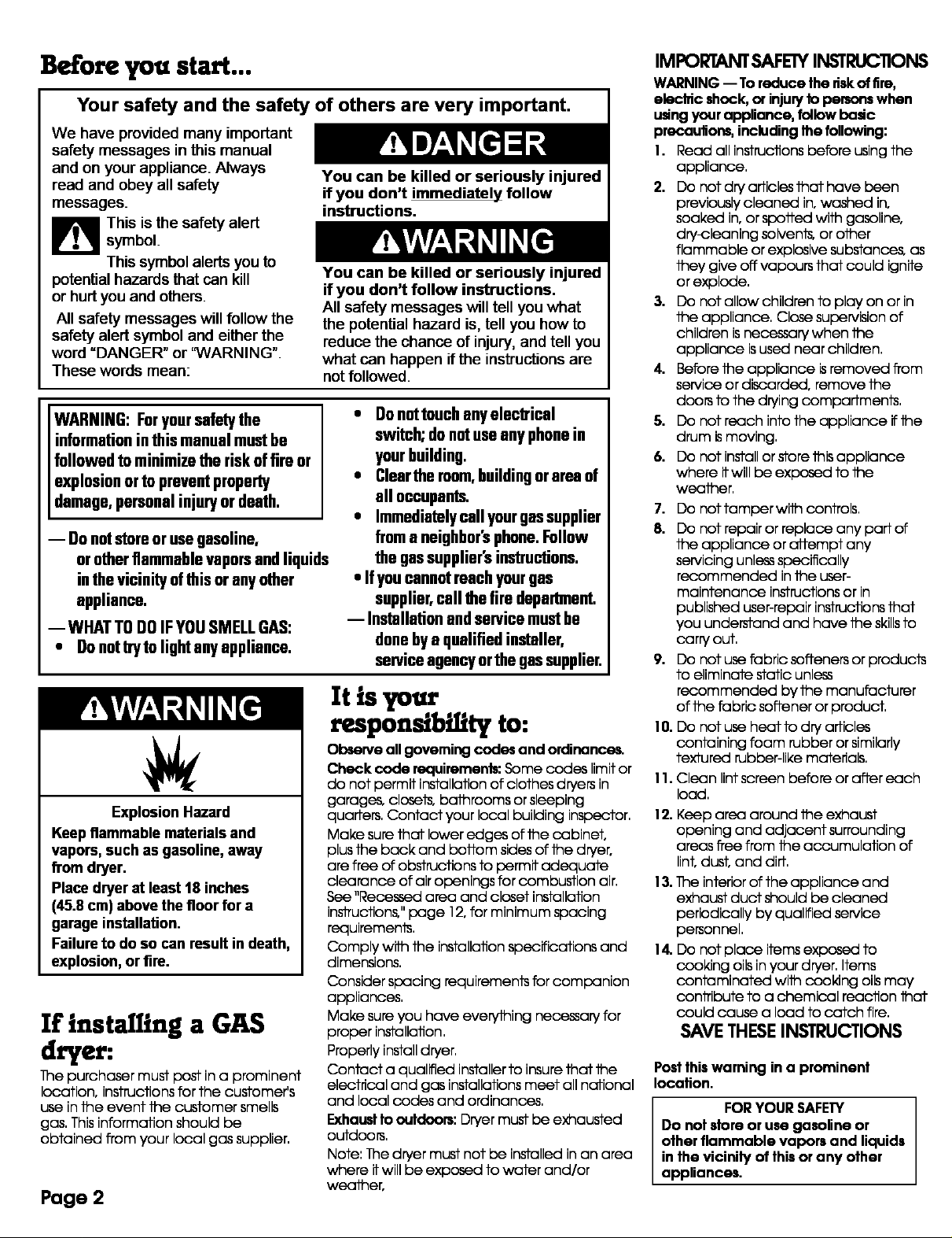
Explosion Hazard
Keep flammable materials and
vapors, such as gasoline, away
from dryer.
Place dryerat least 18 inches
(45.8cm) above the floor for a
garage installation.
Failureto do so can result in death,
explosion, or fire.
If installing a GAS
dryer:
11nepurchaser must post in a prominent
location, instructions for the customer's
use in the event the customer smells
gas, This information should be
obtained from your local gas supplier,
Page 2
garages, closets, bathrooms or sleeping
quarters, Contact your local building inspector,
Make sure that lower edges of the cabinet,
plus the back and bottom sides of the dryer,
are free of obstructions to permit adequate
clearance of air openings for combustion air,
See "Recessed area and closet installation
inslTuctions," page 12, for minimum spacing
reduirements,
Comply with the installation specifications and
dimensions,
Consider spacing requirements far companion
appliances,
Make sure you have everything necessary for
proper installation,
Properly install dryer,
Contact a qualified installer to insure that the
electrical and gas installations meet all national
and local codes and ordinances,
Exhaust to outdoom: Dryer must be exhausted
outdoors,
Note: The dryer must not be installed in an area
where it will be exposed to water and/or
weather,
IMPORTANTSAFEWINSTRUC11ONS
WARNING -- To reduce the dskof fire,
elecldc shock, or injury to persons when
udng your appliance, follow badc
precautions, including Ihe following:
1. Read all instructionsbefore using the
appliance,
2. Do not dry articles that have been
previously cleaned in, washed in,
soaked in, or spelted with gasoline,
dry-cleaning solvents, or other
flammable or explosive substances, as
they give off vapours that could ignite
or explode,
3. Do not allow children to play on or in
the appliance, Close supervision of
children is necessary when the
appliance isused near children,
4. Before the appliance isremoved from
service or discarded, remove the
doors to the drying compartments,
5. Do nat reech inta the appliance if the
drum ismoving,
6. Do nat install or stare this appliance
where itwill be exposed to the
weather,
7. Do nat tamper with cantrols,
8. Do not repair or replace any part of
the appliance or attempt any
servicing unless specifically
recommended in the user-
maintenance instructions or in
published user-repair instructions that
you understand and have the skillsto
carry out,
9. Do not use fabric softeners or products
to eliminate static unless
recommended by the manufacturer
of the fabric softener or product,
10. Do not use heat to dry articles
containing foam rubber or similarly
textured rubber-like materials,
1I. Clean lint screen before or after each
load,
12. Keep area around the exhaust
opening and adjacent surrounding
areas flee from the accumulation of
lint, dust, and dirt,
13. 11neinterior of the appliance and
exhaust duct should be cleaned
periodically by qualified service
personnel,
14. Do not place items exposed to
cooking oils in your dryer, Items
contaminated with caokJng oiLsmay
canlTibute to a chemical reaction that
could cause a load to catch fire,
SAVE THESEINSTRUCTIONS
Post this warning in a prominent
location.
FOR YOUR SAFEW
Do not store or use gasoline or
other flammable vapors and liquids
in the vicinity of this or any other
appliances.
The collar houses the accumulator
timers with actuating arm and bufton,
The timers are set to provide 45
minutes (4 pins) of drying time when
activated by the coin slide, Timer
cams for 30-minute (6 pins) and 60-
minute (3 pins) drying times are
included in the parts bag,
The coin-slide mechanism, control
panel lock and key, and coin-box lock
and key are not included and are
available from usual industry sources,
To change to a
30- or 60-minute
timingcam
Electrical Shock Hazard
Disconnect power before
servicing.
Replace all parts and panels
before operating.
Failure to do so can result in
death or electrical shock,
Each coin-operated dryer is
equipped with a 45-minute timer
cam that provides 45 minutes of
drying time when activated by the
coin slide,
You can install the 30-minute or
60-minute timing cam (shipped with
dryer) as follows:
1. Unlock control panel, Lift up and
rotate out from cabinet, Control
panel will still be aftached to
cabinet,
2. Reach into control panel area,
Use Phillips screwdriver to loosen
(but not remove) timer mounting
bracket screw, Lift up to remove
timer assembly and bracket from
cabinet,
ratchet tooth
timing cam
3. Turn the timing cam by hand until
the "V'-shaped notch lines up
below the ratchet tooth,
ratchet tooth timing cam
Line L lug
notch to
clear
ratchet hub
tooth, down
4. Insert a narrow, flat-blade
screwdriver under the timing cam
near the clock shaft, Gently lift cam
straight up and off shaft making
sure that the "V" -shaped notch
clears the ratchet tooth,
5. Place new cam (hub side down)
over clock shaft, Line up flat side of
shaft with flat side of cam hole,
Check that drive lug is in place,
6. Turn cam until "V" -shaped notch
lines up with ratchet tooth,
7. Press cam down in place on motor
shaft, Make sure that "V" -shaped
notch clears the ratchet tooth,
8. Reaftach the timer bracket
assembly; then tighten the screws,
9. Repeat steps for other timer,
10. Close and lock the control panel,,
drive
Exhaust
requirements
Fire Hazard
Use a heavy metal vent.
Do not use a plastic vent.
Do not use a metal foil vent.
Failure to do so can result in
death or fire.
Do not use non-metal flexible vent,
metal vent that is smaller than four
inches in diameter or exhaust hoods
with magnetic latches,
The dryer must be exhausted outdoors.
Do not exhaust dryer into a gas vent,
chimney, wall, ceiling, or concealed
space of a building,
Do not install flexible vent in enclosed
walls, ceilings or floors,
If using an existing exhaust system,
clean lint from entire length of exhaust
system, Make sure exhaust hood is not
plugged with lint,
The exhaust system should be
inspected and cleaned yearly,
Replace any plastic or metal foil
exhaust vent with rigid metal or
flexible metal vent,
Use 4" (10,2 cm) vent clamps to
secure vent system,
exhaust airflow
better FI good r=1
Four-inch (10.2 cm) metal exhaust vent
isrequired, Plan installation to use the
fewest number of elbows and turns,
Metal flexible vent must be fully
extended and supported when the
dryer isin its final position, DO NOT
KINK OR CRUSH THE VENT, The metal
flexible vent must be completely
open to allow adequate exhaust air
to flow.
Allow as much room as possible
when using elbows or making turns,
Bend vent gradually to avoid kinking,
Remove excess flexible vent to avoid
sagging and kinking that may result in
reduced air flow,
Exhaust outlet is located at the
center of the boftom dryer back,
The exhaust vent can be routed up,
down, left, right, behind the dryer or
straight out the back of the dryer,
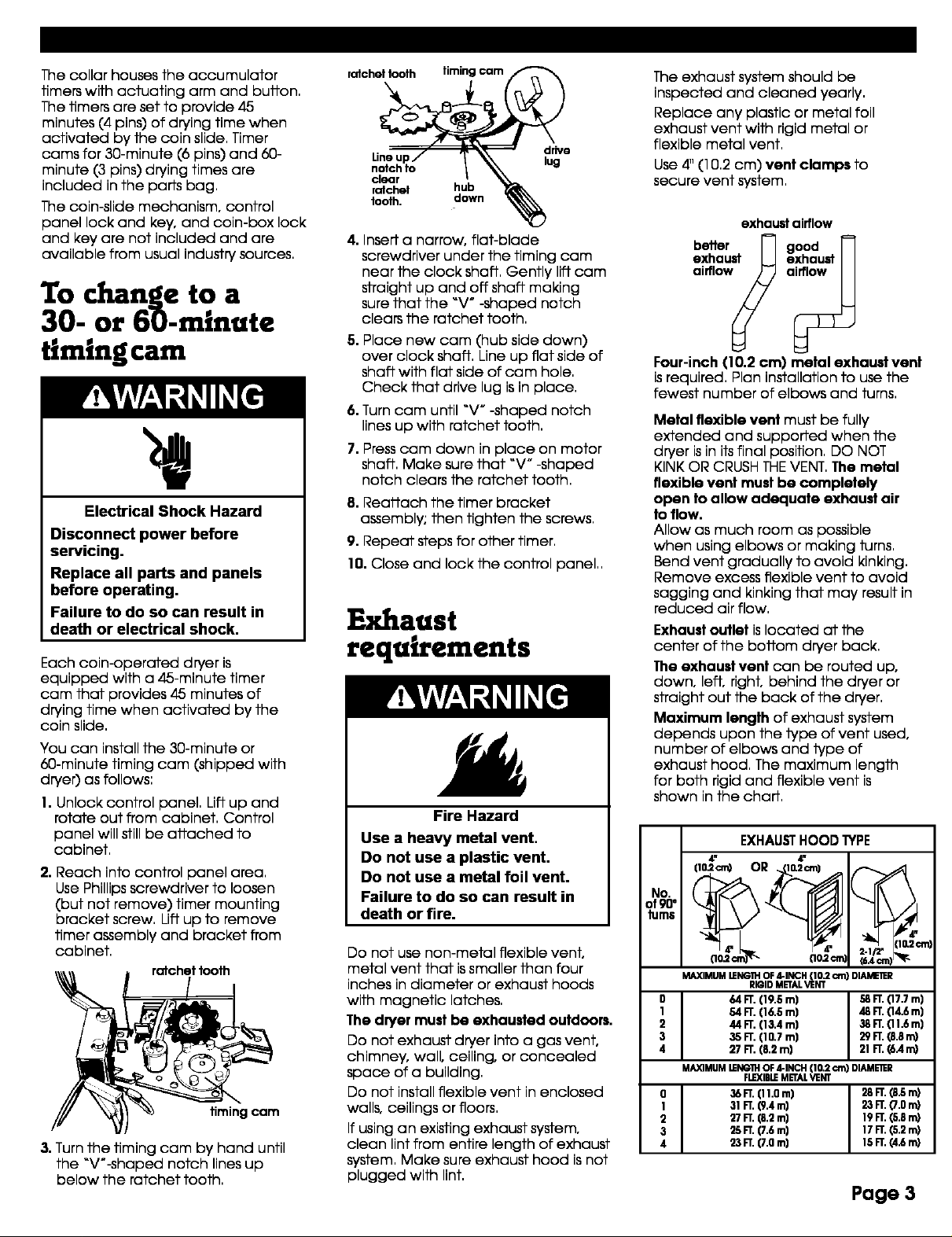
Maximum length of exhaust system
depends upon the type of vent used,
number of elbows and type of
exhaust hood, The maximum length
for both rigid and flexible vent is
shown in the chart,
EXHAUSTHOOD TYPE
4" 4"
(i0=c_ OR .._j_2cr_ /_.,..._
.o
MAXIMUMLENG1HRIGIDOFMETAL4"INCH_NT10"2_ DIA_RR
0 64FT.119.5m] 58FT.(17.7m]
I 54FT.(16.5m] 48FT.114.6m]
2 44FT.(13.4 m] 38FT.111.6m]
3 36FT.(10.7m) 29FT.18.8m)
4 27FT.(8.2m) 21FT.(6An0
MA)QMUMLENGIHOF4-INCH(I0.2 cm) DIAMEI_R
O 36FT.(11.0 m] 26 FT.(8,Sm)
I 31 FT.19.4m] 23 FT.17.0m)
2 27 FT.18.2m) 19 FT.(5.8 m)
3 25 FT.(7.6 m] 17 FT.(5.2 m)
4 23FT.(7.0m] 15FT.14.6m)
FLE(IBLEMETAL VENT
Page 3

For exhaust systems not covered by
the exhaust length chart, see
Whirlpool Service Manual, "Exhausting
Whirlpool Dryers," Part No, 603197,
available from your Whirlpool parts
distributor,
If dryer is installed in a confined area,
such as a bedroom, bathroom or
closet, provision MUST BE made for
enough air for combustion and
ventilation, (Check governing codes
and ordinances,) See "Recessed area
and closet installation instructions =on
Page 12,
An exhaust hood should cap the
exhaust vent to prevent exhausted air
from returning into the dryer, The
outlet of the hood must be at least
12 inches (30,5 cm) from the ground
or anything else that may be in the
path of the exhaust,
Four-inch outlet hood is preferred.
However, a 2-1/2-inch (6,4 cm) outlet
exhaust hood may be used, A
2-1/2-inch (6,4 cm) outlet creates
greater back pressure than other
hood types, For permanent
installation, a stationary exhaust
system is required,
A main exhaust vent can be used for
exhausting a group of dryers, Main
exhaust vent should be sized to
remove 200 CFM of air per dryer,
Large-capacity lint screens of proper
design may be used in the main
exhaust vent if checked and cleaned
frequently, The room where the dryers
are located should have make-up air
equal to or greater than the CFM of
all the dryers in the room,
airflow _ molncoHecforvent
Back-draft Damper Kits, Part No,
339191 B,are available from your
Whirlpool dealer and should be
installed in each dryer's exhaust vent
to prevent exhausted air from
returning into the dryers and to keep
the exhaust in balance within the
main exhaust vent, Unobstructed air
openings are required,
Each exhaust vent should enter the
main vent at an angle pointing in the
direction of the airflow, Vents entering
from the opposite side should be
staggered to reduce the exhausted
air from interfering with the other
vents,
The maximum angle of each vent
entering the main vent should be no
more than 30 °,
Keep air openings free of dry
cleaning fluid fumes. Fumes create
acids which, when drawn through the
dryer heafing units, can damage
dryers and loads being dried.
A clean-out cover should be located
on the main exhaust vent for
periodically cleaning of the exhaust
system,
An exhaust hood should cap the
outside end of the main vent to
prevent exhausted air from returning
to the dryers, If an exhaust hood
cannot be used, the outside end of
the main vent should have a sweep
elbow directed downward, If the
main vent travels vertically through
the roof, rather than through the wall,
install 180 ° sweep elbow on the end
of vent at least 2 feet (61 cm) above
the highest part of the building, The
opening wall or roof shall have a
diameter 1/2 inch (1,3 cm) larger than
the exhaust vent diameter, The
exhaust vent should be centered in
the opening,
exhaust
hood or _wall
main exhaust vent
iU--;ta'-nt
_,i[ wall
180°
2fl.(61cm) _ Jelbow
highest intof
min.above _ _
buil_inlg maincollector
Do Not install screening or cap over
end of vent,
sweep
Gasrequirements
Explosion Hazard
Use a new AGA or CSA approved
flexible gas supply line.
Install a shut-off valve.
Securely tighten all gas
connections.
If connected to LP, have a
qualified person make sure gas
pressure does not exceed t3"
(33 cm) water column. Examples
of a qualified person include
licensed heating personnel,
authorized gas company
personnel, and authorized
service personnel.
Failure to do so can result in
death, explosion, or fire.
OBSERVEALLGOVERNINGCODES
AND ORDINANCES.
Am This installation must conform
with local codes, or in absence of
local codes with the National Fuel
Gas Code ANSI Z223,1/NFPA 54,
B mThe design of this dryer has
been certified by the CSA
International for use at altitudes up to
1g,000 feet (3048 m) above sea level
at the B,T,U, rating indicated on the
model/serial plate, Burner input
adjustments are not required when
the dryer is operated up to this
elevation,
When installed above 1g,000 feet
(3048 m), a four percent (4%)
reduction of the burner B,T,U, rating
shown on the model/serial plate is
required for each 1,go0 foot (305 m)
increase in elevation, For assistance
when converting to other gas types
and/or installing above 10,000 feet
(3048 m) elevation, contact your
local service company,
Page 4
 Loading...