

Page 1
IMPORTANT
INSTALLATION INSTRUCTIONS
for
Electrical Supply
115-208/230 V.3-Wire
60 Hz—1 Ph.
NOTICE:
ICE STORAGE BIN SUPPLIED
SEPARATELY.
It is essential that a suitable ice storage bin
of durable construction be used with the ice
cube maker and that the method of mounting
be dimensionally compatible.
NOTICE: The interior walls of the ice maker
should at least line up with the interior
walls of the storage bin. There should not be
any interior ledge projection of the bin walls.
An overhang of the ice maker exterior walls
is permissible.
COMMERCIAL ICE MAKER
MODELS
CHCH8AE CHCH8WE CHCH8AS CHCH8WS
Benton Harbor, Michigan. Automatic Washers, Clothes Dryers,
Freezers, Refrigerator-Freezers, Ice Makers, Dishwashers, Built-in
Ovens and Surface Units, Ranges, Microwave Ovens, Compactors,
Room Air Conditioners, Dehumidifiers, Central Heating and
Air Conditioning Systems.
Part No. 756832
Page 2
GENERAL INFORMATION
LOCATE
THIS UNIT MUST BE ,
INSTALLED IN AN * . .
AREA PROTECTED FROM OPERATING I BEST
THE ELEMENTS, SUCH I I RANGE
AS WIND, RAIN, WATER 55-f
SPRAY OR DRIP.
1. Unit must be at least 3" from back wall for air cir
culation. Adequate air circulation must be provided on top
and other sides for performance.
2. If air cooled ice maker is installed in a closed room, 1000
C.F.M. of air must be exchanged through the room to main
tain the room air at 10° F. warmer than the available
ambient air temperature.
3. The head may be installed on either a Whirlpool bin or
field-constructed bin. In either case, be sure the floor will
support the combined weight of the ice maker and the
stored ice cubes. (Approximately 300 lbs. per leg, if using a
Whirlpool bin.)
4. Level bin before installing head. The ice maker head
must be level to insure proper water flow over the freezing
plates.
If height of ice maker exceeds 90" when installed on a
Whirlpool bin and bin expander a leg kit model CECK3
must be used for additional stability.
UNPACK
This item is heavy. When handling, use proper equipment and
care to protect it, yourself, stairs and floors.
1. Using 2" x 4" blocks or shipping foam corners carefully
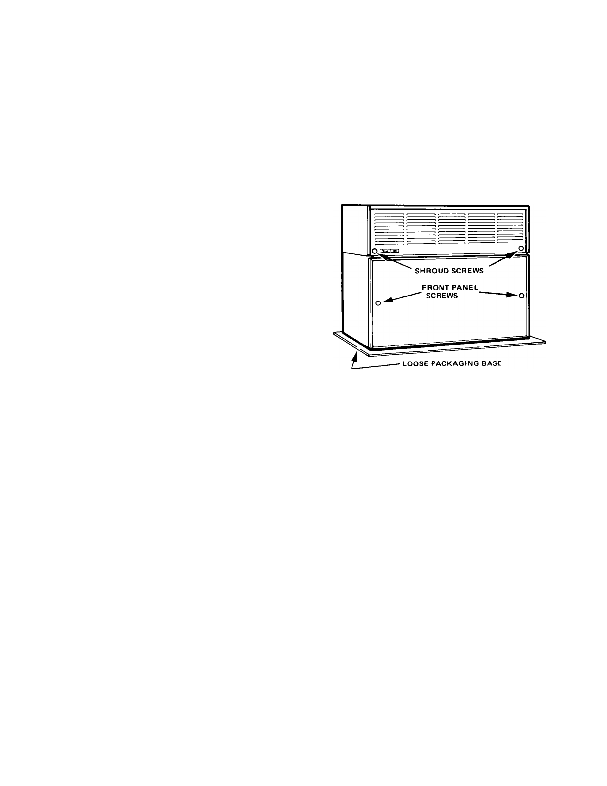
lay cabinet on its back to remove packaging base.
CAUTION: Packaging base is not attached to product.
2. Leaving shipping tape in place, use proper equipment to
carefully position the ice maker head on bin. Always lift
the head to move it into position to avoid damaging the
gasket between the bin and head.
NOTE: On a field-supplied bin, a food grade silicone rubber
sealant must be used to insure a tight seal between the head
and bin.
TO INSTALLER
This machine is shipped from the factory with 15.6 Volts
supplied to the cutter grids.
If in your area the water or low voltage conditions cause
ice slabs to pile up on the cutter grids, a higher voltage
tap on the transformer secondary may be wired to the
cutter grids.
Check the information label at the transformer.
Water treatment may be advisable because poor quality
water can cause marginal operation or malfunction and
increase cleaning frequency and maintenance costs.
Contact your local Whirlpool Commercial Ice Machine
Dealer for recommendations.
3. Fasten the head to the bin with screws and brackets
provided. (Screws are in cabinet sides and back. Brackets
are in small parts bag.) Use two brackets on back and one
on each end towards front corners.
4. Remove front panel by removing two screws and lifting
panel off.
5. Examine carefully for concealed damage. If damaged,
save the carton and have carrier examine product and make
inspection report,
6. Remove all tape, cardboard, and packaging materials
from inside ice maker head, i.e. expansion valve shipping
pad and water float tape.
Page 3
FOR THE ELECTRICIAN
CONFORM TO ALL APPLICABLE CODES
It IS the personal responsibility and obligation of the
customer to contact a qualified installer to assure that the
electrical installation is adequate and is in conformance
with the National Electrical Code and local codes and
ordinances
NOTE: A separate circuit must be used with 20 ampere
time delay fuses.
REMOVE TOP SHROUD
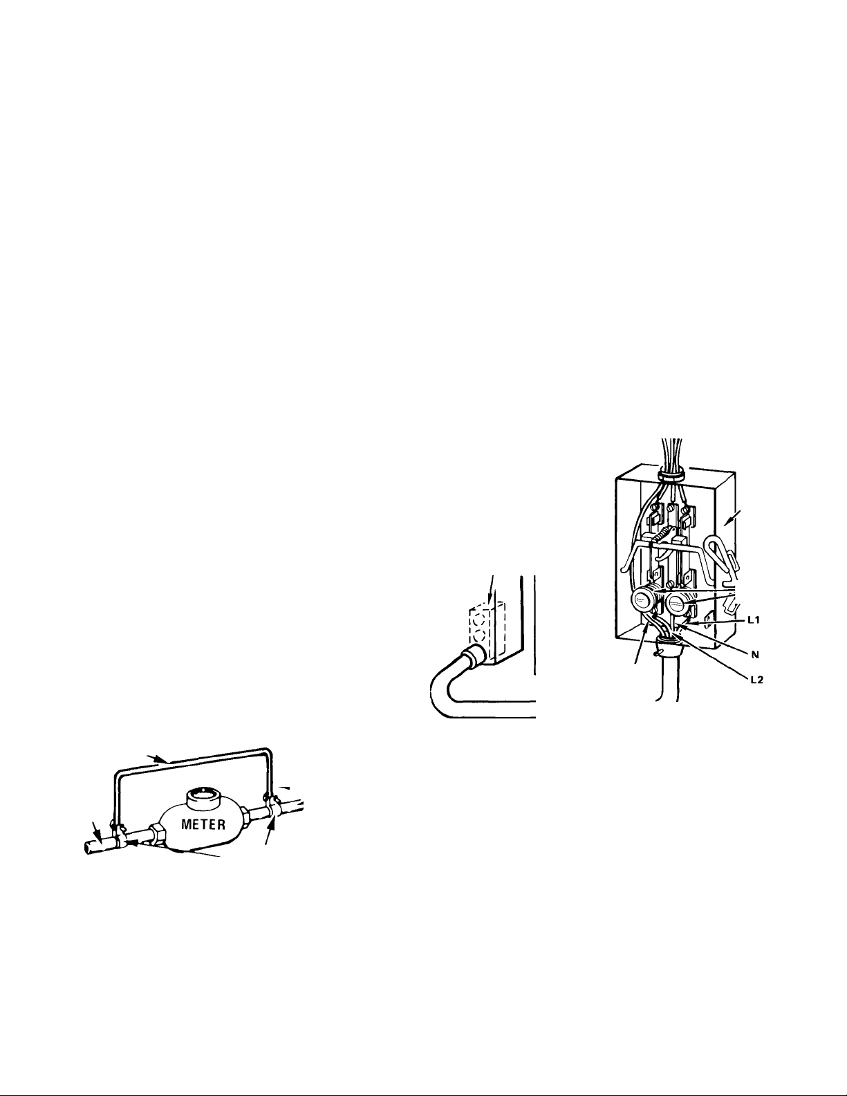
1. Loosen screws on lower front corners of shroud.
INSTALL ELECTRICAL WIRING
COPPER WIRE ONLY
115-208/230 V, 3-Wire, 60 Hz, 1 Ph, 20 Amp Time Delay Fuses
Install wiring according to Local and National Electrical
Codes into junction box provided at rear of cabinet. Replace
electrical box cover and shroud.
2. Pull complete shroud forward and lift off.
CAUTION:
part.
Use proper care when handling this awkward
INSTALL GROUNDING WIRE
COPPER WIRE ONLY
1. Permanently ground this ice maker in accordance
with the National Electrical Code and local codes and
ordinances GROUND MUST BE CONTINUOUS
2. Use a copper conductor of the appropriate size
from the ice maker green grounding wire to a grounded
connection in the service panel or a properly driven and
electrically grounded rod.
3. Replace electrical junction box cover
4. Replace shroud.
Alternate (Not Recommended)
1. If the recommended grounding method is impossible,
permanently ground the appliance from the green ground
ing screw to a grounded cold water pipe*using a separate,
green colored, insulated copper conductor of appropriate
size, THIS, HOWEVER IS NOT RECOMMENDED.
NOTE: Do not ground to a gas supply pipe Do not con
nect to electric power supply until appliance is perma
nently grounded
JUMPER WIRE
METAL
WATER
PIPE
CLAMP
N0.4 COPPER
WIRE
MINIMUM^
GROUNDED
METAL COLD
WATER PIPE
PROVIDE A FUSED DISCONNECT BOX WITHIN SIGHT AND EASY REACH OF THE ICE MAKER.
Be sure power supply is within + 10% - 5% of recommended
voltage when machine is in operation.
TO SERVICE
PANEL
DISCONNECT
BOX
ICE MAKER
ELECTRICAL
JUNCTION BOX
20 AMP TIME DELAY FUSES
PERMANENT AND
CONTINUOUS
GROUND (GREEN)
RIGID OR
FLEXIBLE
CONDUIT
CR-119
Cold water pipe must have metal continuity to electrical ground and
not be interrupted by plastic, rubber or other electrically insulating
connectors (including water meter or pumpi without adding a copper
jumper wire at these connections.
Page 4
FOR THE PLUMBER
CONFORM TO ALL APPLICABLE CODES
INSTALL DRAINS
%' O.D. RUBBER TUBE
CONDENSATE DRAInH«
y." O.D. TUBE SUPPLIED
WITH WHIRLPOOL BIN
AIR VENT-
TO OPEN DRAIN
FROM ICE MAKER PUMP PAN
t
-
-----
№
1/8” SIPHON HOLE
VFPT
BIN DRAIN
/
V
NOTE: The Va" dia. siphon break hole must be in
vertical leg of white vinyl tubing.
The storage bin drains by gravity and, therefore, the drain
line must maintain gradual slope to an open drain re
ceptacle. Any rise in the drain line will cause an air lock
which will prevent the water from draining from the stor
age bin. Installation of an air vent in the drain line will
eliminate the possibility of an air lock forming.
the
CONDENSER DRAIN
NEEDED ONLY ON WATER COOLED MODELS CHCH8WE, CHCH8WS
1. V2" galvanized pipe or copper tubing must be used to
extend the condenser outlet to an open type dram.
2. Adequate flow rate must be maintained through the
condenser. Runs over 40 ft. will require using larger pipe size.
*NOTE: These drains may be connected to a disposal
system if high humidity or condenser cleaning causes liquid
in the sump areas.
INSTALL WATER SUPPLY
Water treatment may be advisable because poor quality
water can cause marginal operation or malfunction and
increase cleaning frequency and maintenance costs.
Contact your local Whirlpool Commercial Ice Machine
Dealer for recommendations.
WATER COOLED
/3” O.D. RUBBER TUBE
CONDENSATE DRAIN.^
WATER COOLED
MODELS
MPT ICE MAKER
DRAIN TUBE
ICE MAKING HEAD Cold Water Supply V4 o.d. soft copper tube with shut-off valve.
1. A shut-off valve should be provided In the wafer
supply line at a convenient location near the ice maker.
The supply line must be adequately sized to compensate
for the length of the run.
Supply runs over 10 feet should be made with %' o.d.
copper tubing. Runs of 10 feet or less may be made with
I4" o.d. copper tubing.
NOTE: Always flush out water lines before connecting
to prevent foreign matter from entering the float valve.
2. Connect supply line to Va" o.d. copper water line at
center rear of ice making head.
3. Water is controlled in pump reservoir by float valve.
Make sure float valve opens and closes.
4. Water pressure must be 20 to 100 psi. If the pressure
exceeds 100 psi, a regulator will have to be installed. The
unit will operate in pressures below 20 psi; however, it
may produce cloudy ice
CONDENSER
OUTLET
WATER COOLED
CONDENSER INLET
¡/3” O.D.RUBBER TUBE
CONDENSATE DRAiN^
y»-'0 D COPPER TUBE
INLET WATER LINE
CDNDENSER WATER INLET
NEEDED ONLY ON WATER COOLED MODELS CHCH8WE, CHCH8WS
1. Use a 3/8" I.P.S. independent cold water supply to the
water cooled condenser inlet for proper condenser operation.
Runs over 40 ft. will require using larger pipe size.
Page 5
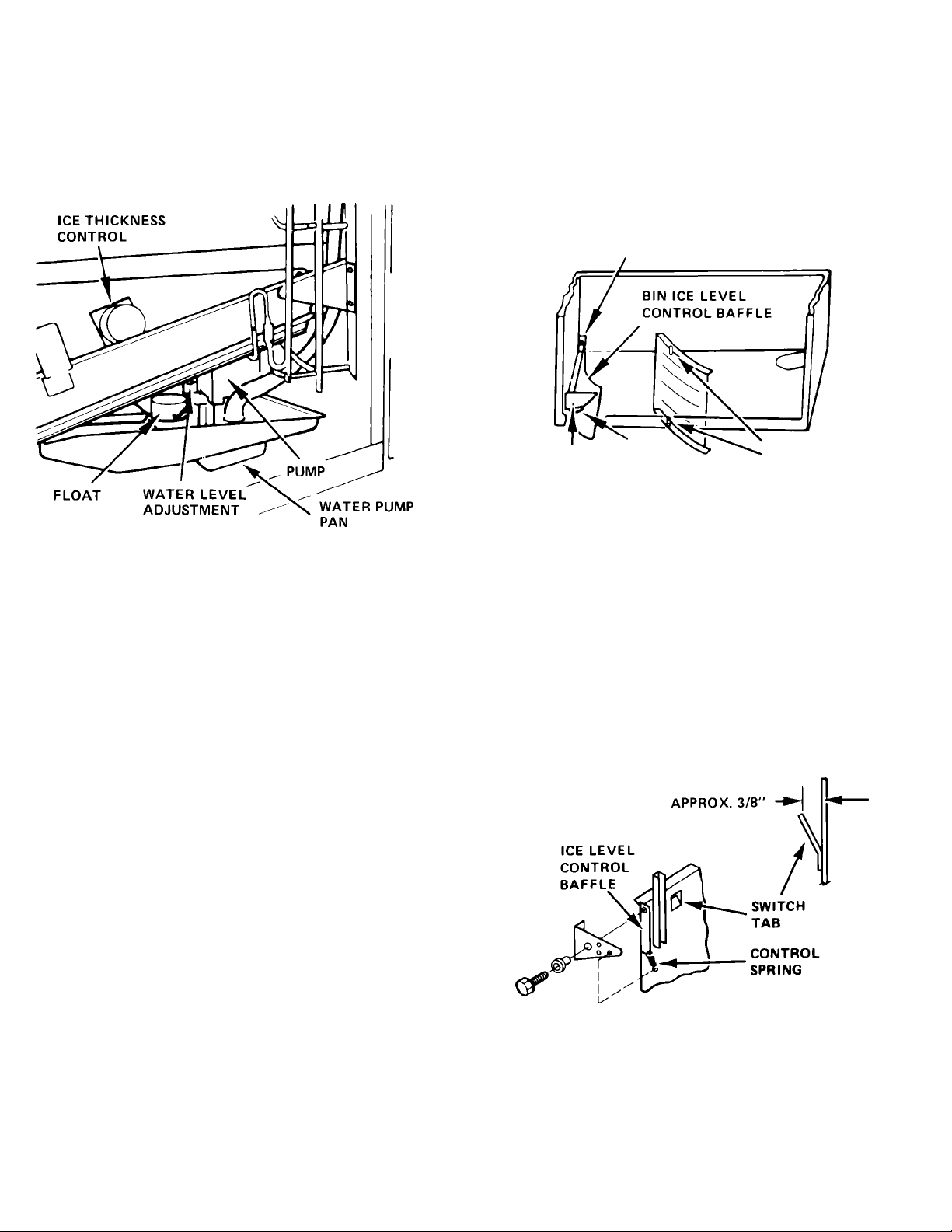
INSTALL LOOSE PARTS
REAR MOUNTING
PIN
The following loose parts packed inside the head will have
to be field installed.
1. Water Pump Pan. Hold pan so the gradually sloped
area is at left. Place the left lip edge between the lower
evaporator and on the top of the entering edge of the
lower cutter grid Raise right end of water pan and place
pan flange on angle bracket attached to right liner wall
Remove packing holding the float valve for shipping
2. Drain Line tor Water Pump Pan. The formed piece of
white vinyl tubing slips over the pump pan drain tube
and the dram tube going through the back wall of the
storage bin or on a field constructed bin run to an open
drain.
NOTE: The1/8"dia siphon break hole must be in ttie
vertical leg of white vinyl tubihg
CAUTION: Insufficient or continuous siphoning may
result from:
a. Reducing the inside diameter of the drain line.
b. Having less than 1/4" per foot fall.
c. Traps or extreme bends in the lines.
BIN CONTROL
SPRING
FRONT MOUNTING
BOLT
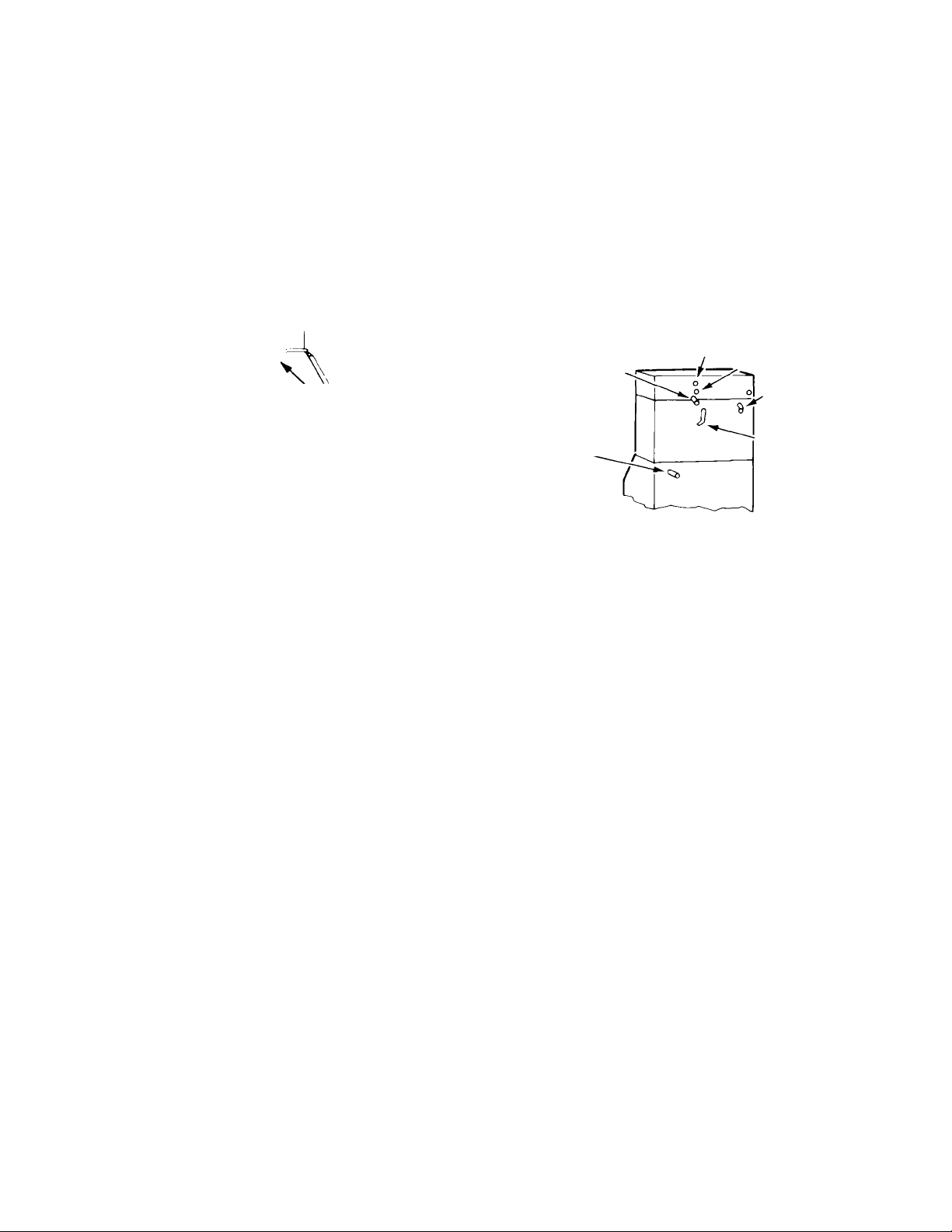
3. Cube Deflector. Flex cube deflector baffle so that it
hangs from pins. Top edge will rest against cutter grid
frame.
4. Ice Level Control Baffle. The ice level baffle must be
installed at the bottom left end of the ice maker head with
the curve inward. Slip the hole in the baffle over the pin in
the back liner wall. Raise up front edge and fasten through
lower support rail by removing and reinserting screw pro
vided. Install spring from baffle to right hand hole in lower
support rail to hold baffle off switch plunger. Weight of ice
against baffle will operate switch.
FLEX CUBE
DEFLECTOR
OVER PINS
NOTE: Baffle must swing freely without binding.
5. Let Baffle Hang Vertically. Move baffle slowly to left
and listen for bin switch "click" to determine that switch
will turn machine
until switch operates.)
"ON" and "OFF." (Adjust switch tab
Page 6
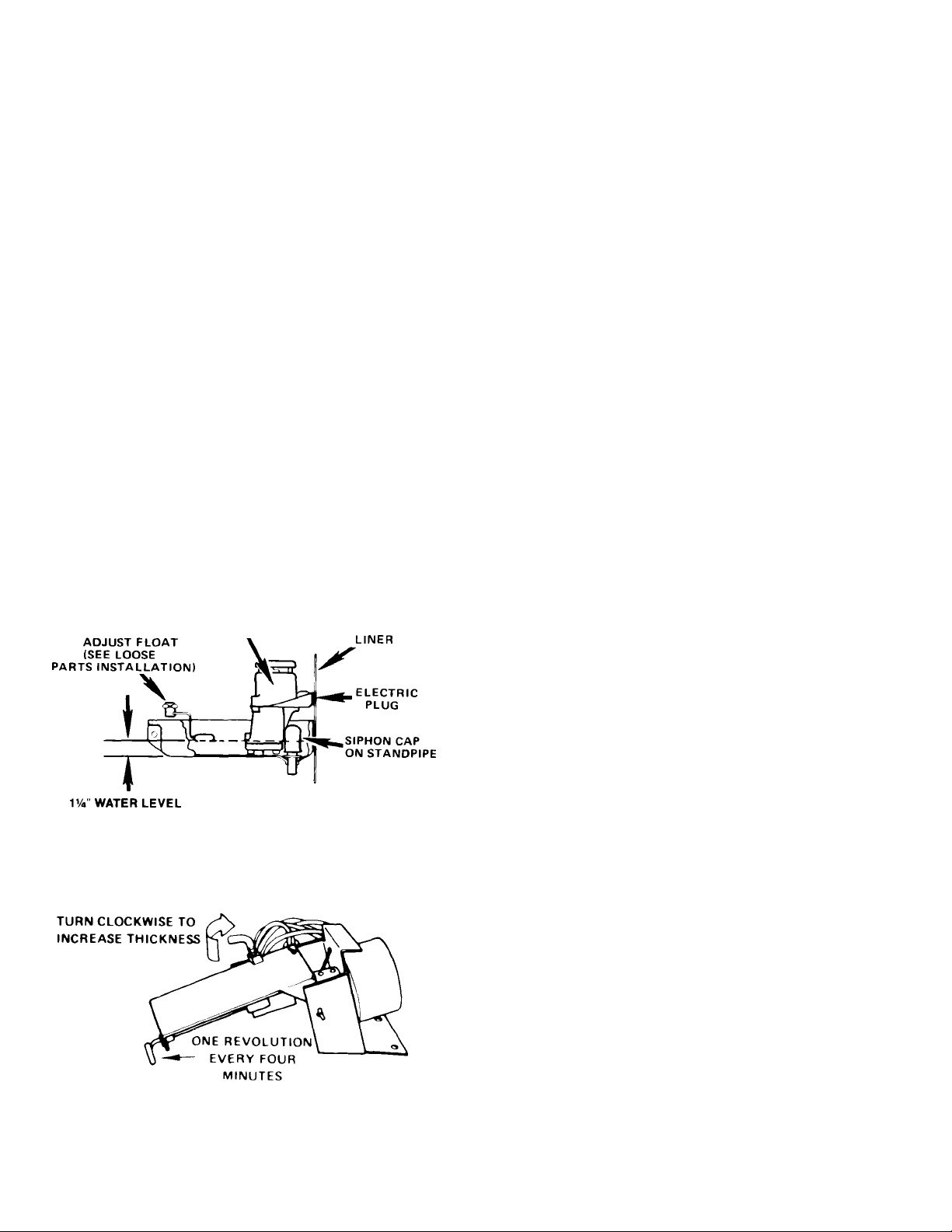
CHECK OPERATION
STA№UP AND CHECK-OFF
1. Start the unit by opening water valve and turning the
service switch to "ON ”
2. NOTE: In "CLEAN" position, only the water pump
operates.
3. Check water level in pump pan. When not running,
water level should be VA" deep.
4. Check for even water flow over freezing plate. Unit
must be level for proper operation.
5. Check freezing plate to make sure it is getting cold.
6. Check cutter grids. Interior temperature limiter above
top grid turns grids "OFF" above 130° F.
7. Check for desired cube thickness and adjust if neces
sary. Maximum capacity will be obtained with ice thick
ness at 1/2" to 5/8". Do not adjust less than 3/8" thick as
machine may malfunction.
8. Replace all panels.
9. Store ice scoop m a clean place.
PUMP
MOTOR
HOW IT WORKS
WITH SERVICE SWITCH IN “ON” POSITION
1. Contactor is energized
2. Compressor runs
3. Condenser fans run
4. Water pump runs
5. Thickness control motor runs
6. Cutter grid warm to touch
NOTE: Grids will be 'OFF ' until temperature limiter
inside cabinet cools to 130° F.
WHEN DESIRED ICE SLAB THICKNESS IS
REACHED, HARVEST CYCLE BEGINS WITH THE
FOLLOWING RESULTS:
1. Thickness control arm raises, actuating switch and
holding relay coil
2. Compressor keeps running
3. Hot gas solenoid valve is energized and opens
4. Condenser fans stop
Condenser water valve closes tightly (Water cooled)
5. Thickness control motor keeps running
6. Water pump stops
7. Water siphons from pump pan and refills
8. Cutter grid warm to touch
MACHINE THEN GOES BACK INTO FREEZE
CYCLE WHILE SLAB IS BEING CUT INTO CUBES
ON CUTTER GRID
WHEN STORAGE BIN GETS FULL, BIN BAFFLE OPENS SWITCH.
1. Slab completion relay keeps machine in freeze cycle until
full ice thickness is reached.
2. Machine then shuts completely off leaving slabs to
defrost by ambient temperature.
3. Cutter grids are "OFF."
HOW IT WORKS-MALFUNCTION LIGHT
1. When the high side pressure raises above the safe
operating limits the machine will shut down because the
blocked condenser thermostat or pressure control
opened and the light will come on.
On air cooled models — this indicates that the condenser
is blocked with dirt and must be cleaned or the con
denser fan motor is not moving air through the finned
condenser.
On water cooled models — this indicates the condenser
has excessive scale inside, water pressure is low, or
water has been shut off.
NOTE: After correcting the malfunction, manually reset
the control.
Page 7
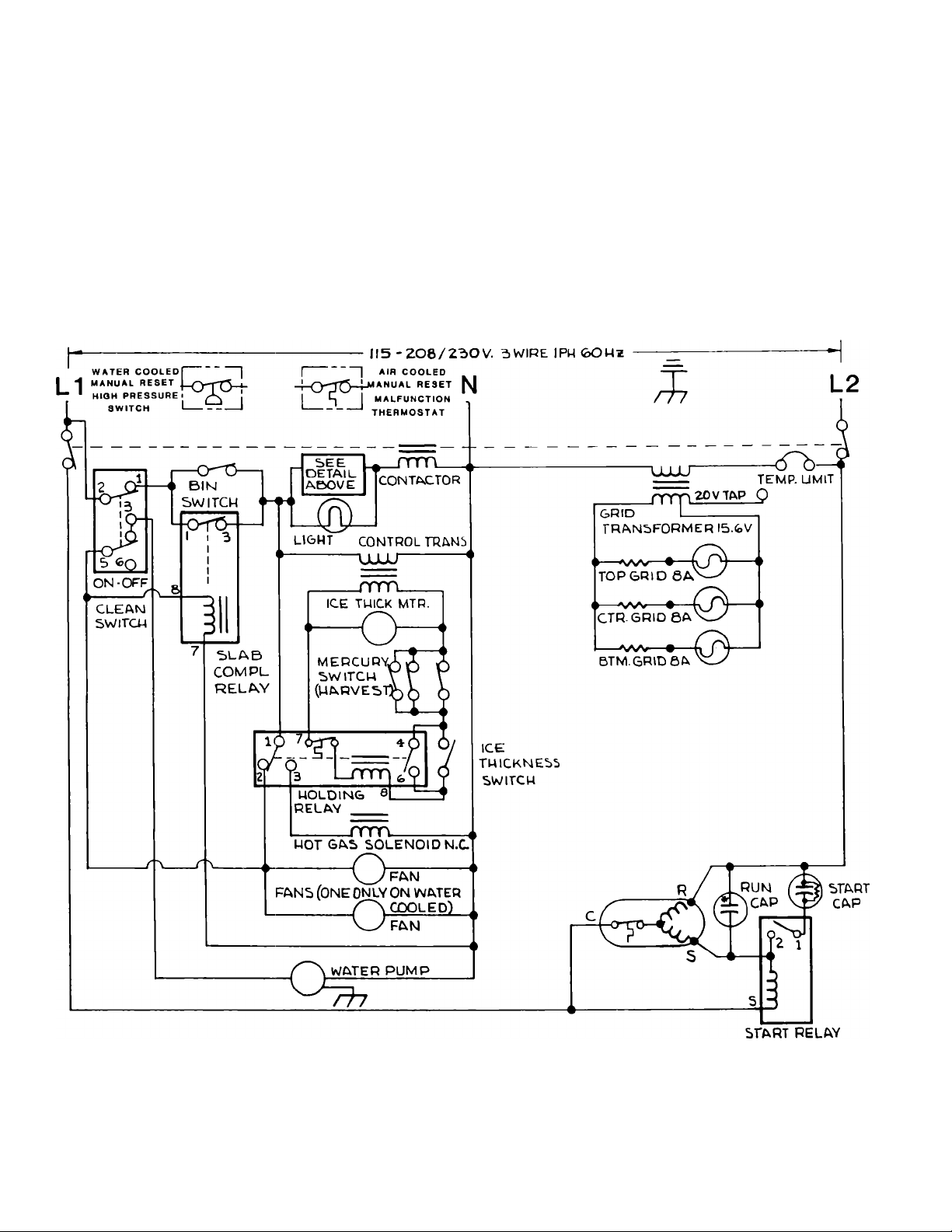
SCHEMATIC WIRING DIAGRAM
DANGER ELECTRICAL SHOCK HAZARD
DISCONNECT POWER BEFORE SERVICING
THIS UNIT MUST BE WIRED AND PERMANENTLY GRDUNDED
in accordance with the National Electrical Code and applicable codes and ordinances
A separate circuit must be used with 20 ampere time delay fuses
Page 8
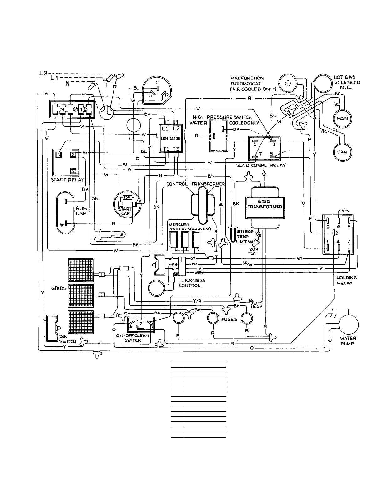
CONNECTION DIAGRAM
LEGEND
BK
BLACK
BR BROWN
R
RED
0 ORANGE
Y
YELLOW
BL
BLUE
V VIOLET
GY GRAY
W
WHITE
BR/U BROWN/WHITE
Y/R YELLOW/RED
P PINK
«
IDENTIFIED TERM.
RC RIP CORD
 Loading...