

Whirlpool CGT9100GQ Installation Manual

INSTALLATION
INSTRUCTIONS
CommerCial StaCked WaSher/dryer
GaS or eleCtriC
INSTRUCCIONES
DE INSTALACIÓN
lavadora/SeCadora ComerCialeS
apiladaS a GaS o eléCtriCaS
TABLE OF CONTENTS
Page
Stacked Washer/Dryer Safety ................................................ 2
Tools and Parts ....................................................................... 5
Alternate Parts and Accessories ........................................... 6
Dimensions/Clearances ......................................................... 7
Stacked Washer/Gas Dryer Installation Requirements ...... 8
Stacked Washer/Electric Dryer
Installation Requirements .................................................... 11
Dryer Venting Requirements ............................................... 15
Dryer Gas Supply Requirements ......................................... 18
Installing Stacked Washer/Dryer ......................................... 19
Washer Drain System ........................................................... 22
Electric Dryer Electrical Connections ................................ 23
Leveling ..................................................................................29
Reversing Dryer Door Swing (Optional) ..............................31
Stacked Washer/Dryer Maintenance Instructions .............34
If You Need Assistance ......................................................... 35
Electronic Control Set-Up Instructions .............................. 36
Warranty ................................................................................ 41
ÍNDICE
Página
Seguridad de la lavadora/
secadora apiladas ................................................................. 42
Herramientas y piezas .......................................................... 45
Piezas y accesorios adicionales ......................................... 46
Dimensiones y espacios libres ............................................ 47
Requisitos de instalación de la lavadora/
secadora a gas apiladas ...................................................... 48
Requisitos de instalación de la lavadora/
secadora eléctricas apiladas .............................................. 51
Requisitos de ventilación de la secadora .......................... 56
Requisitos del suministro de gas de la secadora ............. 59
Instalación de la lavadora/secadora apiladas .................... 60
Sistema de desagüe de la lavadora ..................................... 63
Conexiones eléctricas de la secadora eléctrica ............... 64
Nivelación ............................................................................... 70
Cómo invertir el cierre de la puerta
de la secadora (opcional) .....................................................72
Instrucciones de mantenimiento de la lavadora/
secadora apiladas .................................................................75
Si necesita ayuda ..................................................................76
Instrucciones de programación
del control electrónico ......................................................... 77
Garantía ................................................................................. 83
www.whirlpoolcommerciallaundry.com W10920981A
STACKED WASHER/DRYER SAFETY
n It is recommended that the owner post, in a prominent location, instructions for the customer’s use in the event the customer
smells gas. This information should be obtained from your gas supplier.
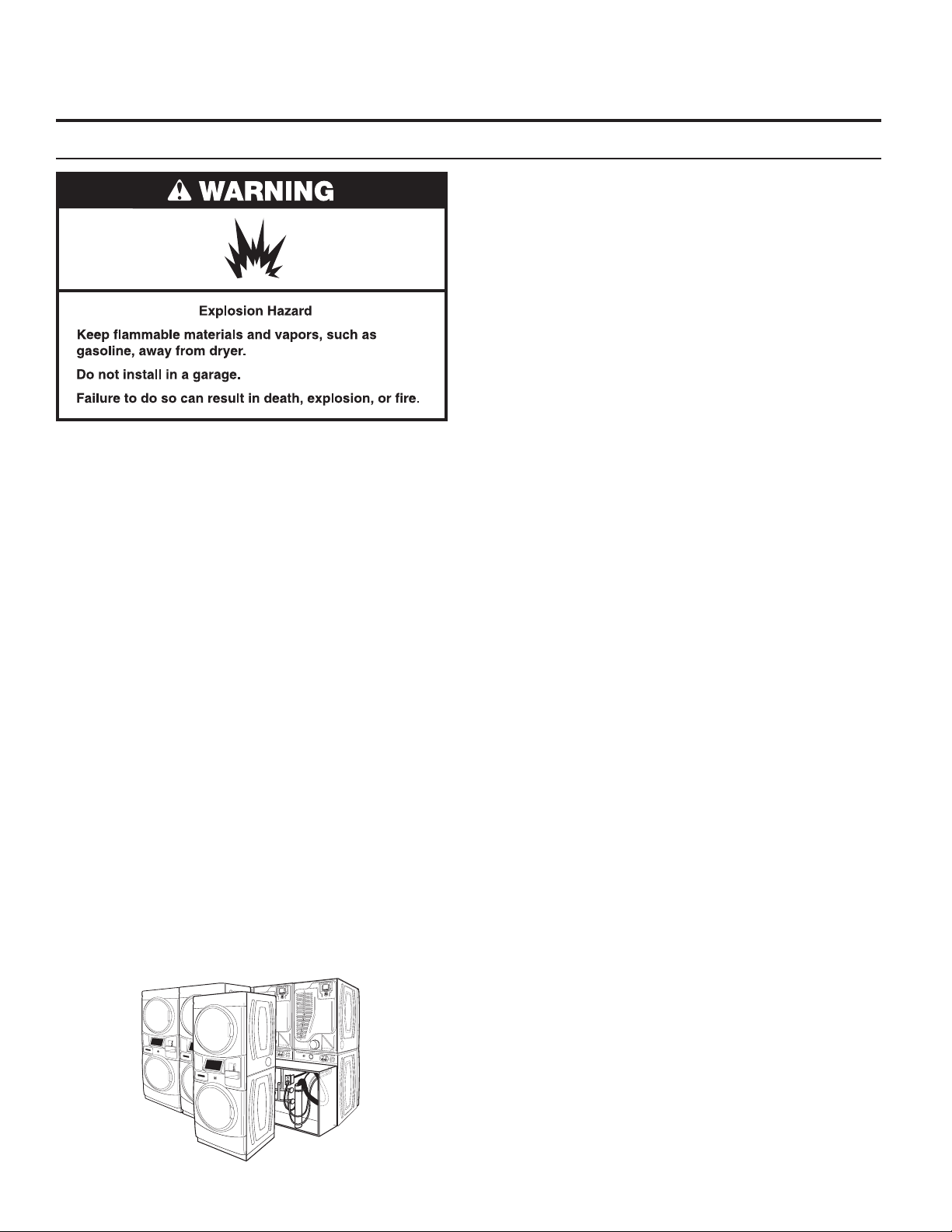
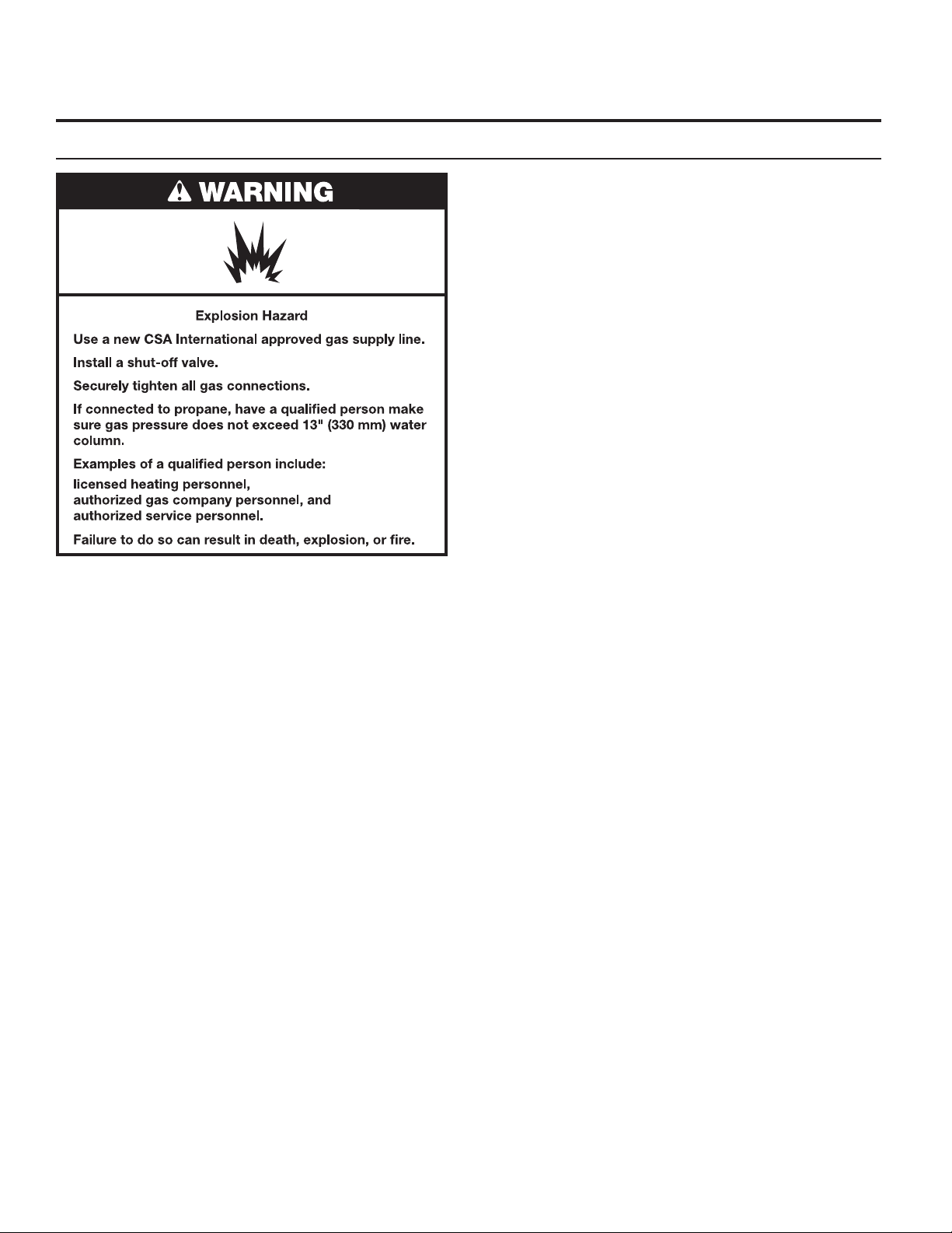
n Post the following warning in a prominent location.
2
STACKED WASHER/DRYER SAFETY
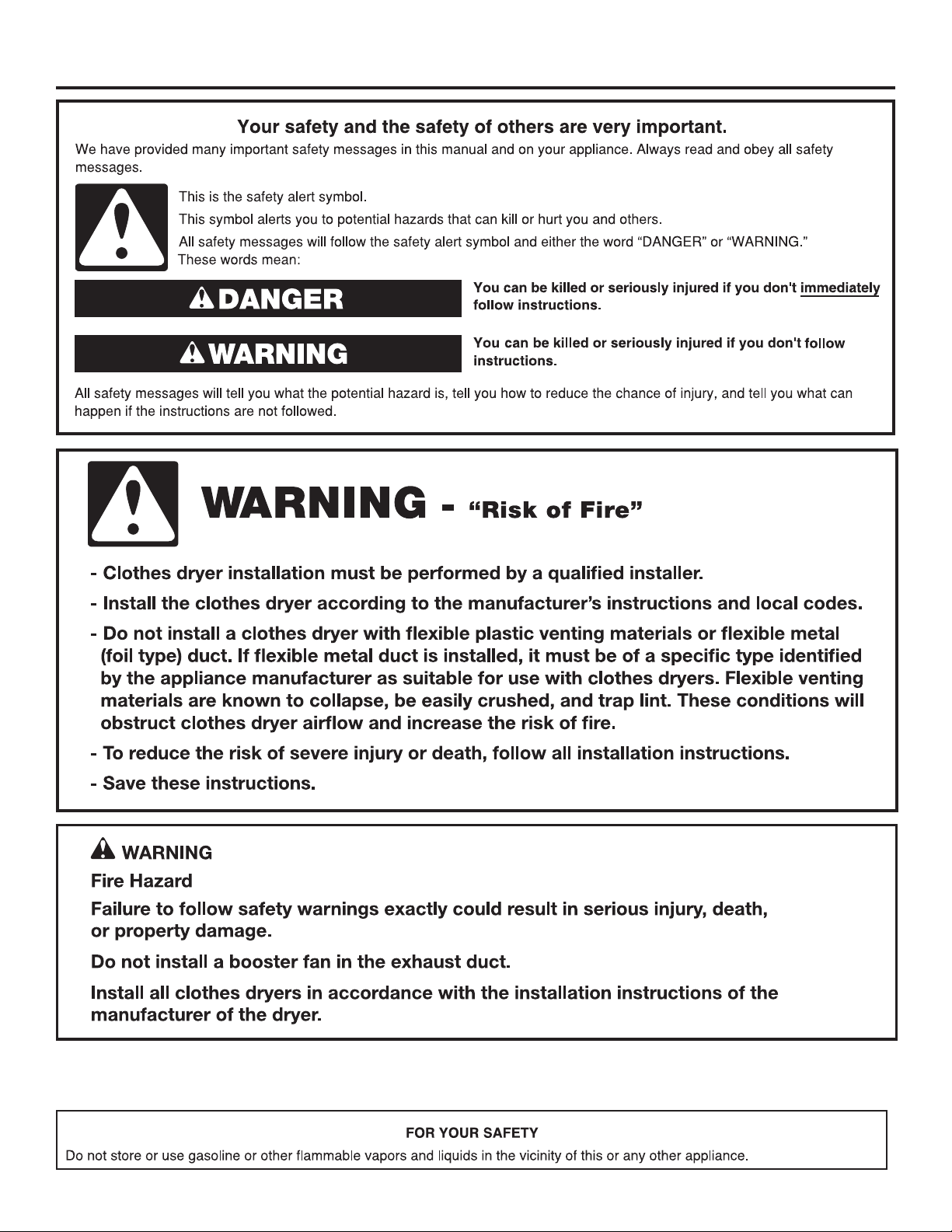
WARNING:
FIRE OR EXPLOSION HAZARD
Failure to follow safety warnings exactly could result in serious injury, death, or property
damage.
–
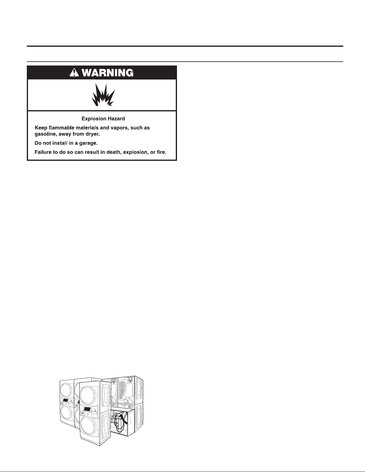
Do not store or use gasoline or other ammable vapors and liquids in the vicinity of this
or any other appliance.
–
WHAT TO DO IF YOU SMELL GAS:
Do not try to light any appliance.
•
Do not touch any electrical switch; do not use any phone in your building.
•
Clear the room, building, or area of all occupants.
•
Immediately call your gas supplier from a neighbor’s phone. Follow the gas supplier’s
•
instructions.
If you cannot reach your gas supplier, call the re department.
•
–
Installation and service must be performed by a qualied installer, service agency, or
the gas supplier.
In the State of Massachusetts, the following installation instructions apply:
■ Installations and repairs must be performed by a qualified or licensed contractor, plumber, or gas fitter qualified or licensed by
the State of Massachusetts.
■ Acceptable Shut-off Devices: Gas Cocks and Ball Valves installed for use shall be listed.
■ A flexible gas connector, when used, must not exceed 4 feet (121.9 cm).
IMPORTANT: The gas installation must conform with local codes, or in the absence of local codes, with the National Fuel Gas
Code, ANSI Z223.1/NFPA 54, or the Natural Gas and Propane Installation Code, CSA B149.1.
The dryer must be electrically grounded in accordance with local codes, or in the absence of local codes, with the National
Electrical Code, ANSI/NFPA 70, or the Canadian Electrical Code, Part 1, CSA C22.1.
3
STACKED WASHER/DRYER SAFETY
4
TOOLS AND PARTS
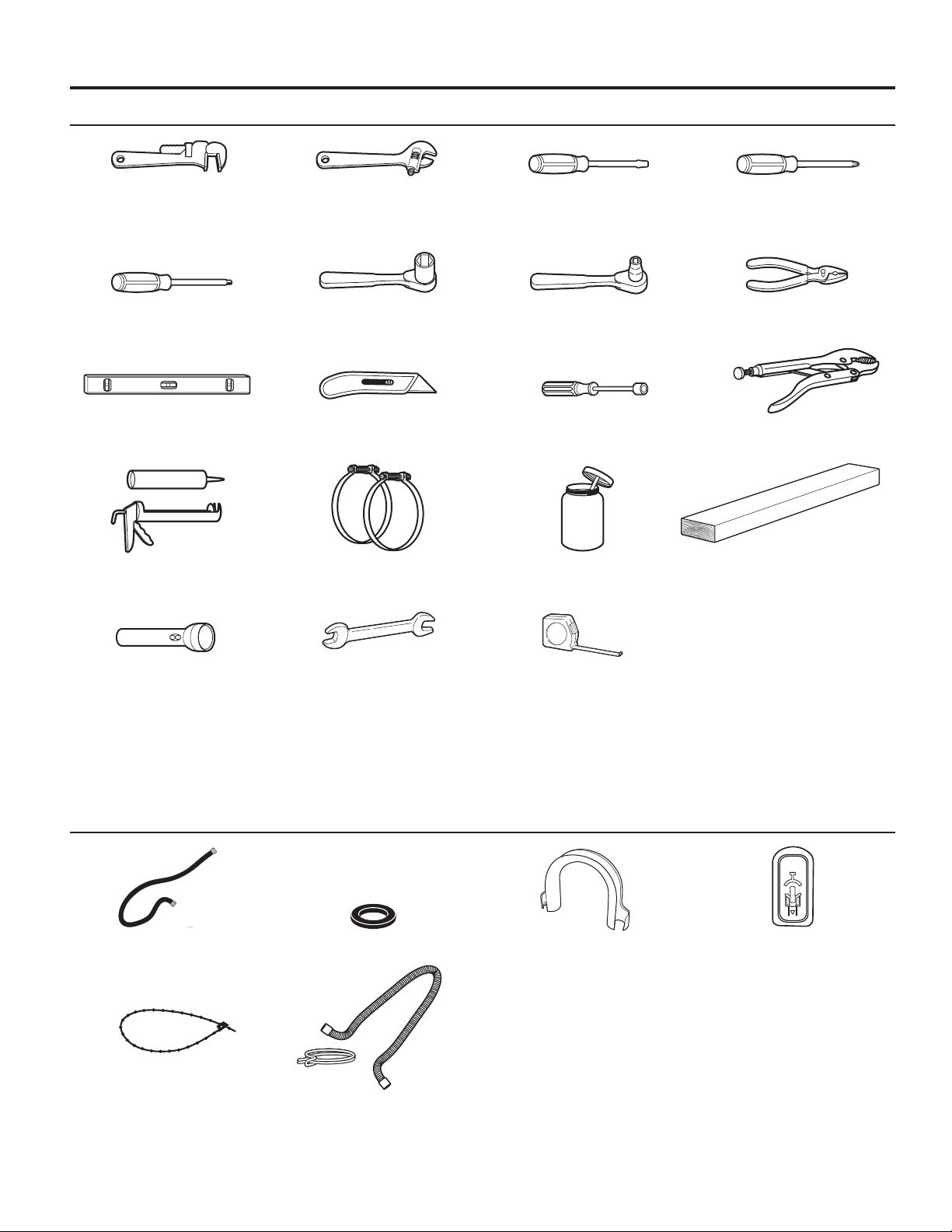
Tools Needed:
8" (203 mm) 8" (203 mm) or 10" (254 mm) Flat-blade screwdriver Phillips screwdriver
or 10" (254 mm) Adjustable wrench
Pipe wrench that opens to 1" (25 mm)
®†
TORX T20
screwdriver or bit socket wrench (that open to 1
Level Utility knife 1/4" (6 mm) Nut driver Locking pliers
Security 1" (25 mm) Hex-head 5⁄16" Socket wrench Pliers
9
/16" [39 mm])
Caulk gun and caulk Vent clamps Pipe-joint compound 27" (686 mm) Wood block
(for installing new exhaust vent) suitable for gas type
Flashlight (optional) 1/2" (13 mm) and 9/16" Ruler or measuring tape
(14 mm) Open-end wrenches
Parts Supplied:
Water inlet hoses (2) Inlet hose washers (4) U-shaped hose form Transit bolt hole plug (4)
Beaded tie strap
Drain hose/clamp
†®TORX and T20 are registered trademarks of Acument Intellectual Properties, LLC.
5
ALTERNATE PARTS AND ACCESSORIES
Alternate Parts
Your installation may require additional parts. If you are
interested in purchasing one of the items listed here, call the
toll-free number in the “If You Need Assistance” section.
If You Have You Will Need to Buy
Overhead sewer Standard 20 gal. (76 L) 39"
1" (25 mm) standpipe 2" (51 mm) diameter to 1" (25 mm)
Drain hose Extension Drain Hose
too short Part Number 285863
Connector Kit Part Number 285835
Lint clogged drain Drain Protector
Part Number 367031
Connector Kit Part Number 285835
Floor drain system Siphon break, Part Number 285834
Water faucets 2 longer water ll hoses:
beyond reach 6 ft. (1.8 m) 90° bend hose
of ll hoses Part Number 76314
10 ft. (3.0 m) Part Number 350008
(990 mm) tall drain tub or utility
sink, sump pump, and connectors
(available from local plumbing
suppliers)
diameter Standpipe Adapter
Part Number 3363920
Connector Kit Part Number 285835
Connector Kit (x2)
Part Number 285835
Extension Drain Hose
Part Number 285863
Accessories
Enhance your washer/dryer with these premium accessories.
For more high-quality items or to order,
call 1-866-698-2538, or visit us at
www.whirlpool.com/accessories.
Part Number Accessory
8212526 Washer drip tray, ts under all
31682 All-purpose appliance cleaner
1903WH Laundry supply storage cart
279818 3-way dryer venting kit
285834 Siphon break kit
6
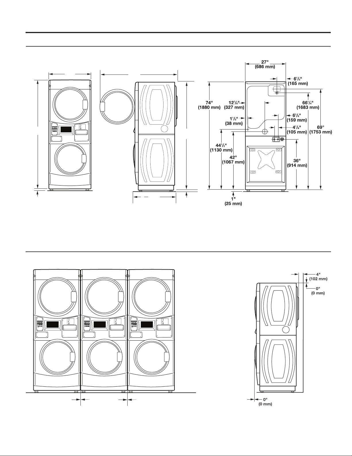
DIMENSIONS/CLEARANCES
Dimensions
Front View Side View Back View
74"
(1880 mm)
1"
(25 mm)
27"
(686 mm)
51"
(1295 mm)
1
/2
29.5 "
(751 mm)
74"
(1880 mm)
1"
(25 mm)
Clearances
Side Clearances Back/Top Clearances
0"
(0 mm)
0"
(0 mm)
7
STACKED WASHER/GAS DRYER
INSTALLATION REQUIREMENTS
Stacked Washer/Gas Dryer Location
Stacked washer/gas dryer installation clearances
n The location must be large enough to allow the washer
n Additional spacing should be considered for ease of
n Additional clearances might be required for wall, door,
n Additional spacing of 1" (25 mm) on all sides of the washer/
n Companion appliance spacing should also be considered.
When installing a gas dryer:
Selecting the proper location for your washer/dryer improves
performance and minimizes noise and possible washer “walk.”
Your washer/dryer can be installed in a basement, laundry
room, or recessed area. This washer/dryer is not intended
for installation in a mobile home or recreational vehicle.
See the “Drain System” section for more information.
Companion appliance location requirements should also
be considered.
IMPORTANT: Do not install or store the washer/dryer where
it will be exposed to the weather. Do not store or operate the
washer/dryer in temperatures at or below 32°F (0°C). Some
water can remain in the washer and can cause damage in low
temperatures. Proper installation is your responsibility.
You will need:
n A water heater set to deliver 120°F (49°C) water to the
washer.
n A grounded electrical outlet located within 6 ft. (1.8 m) of
where the power cord is attached to the back of the washer.
See “Electrical Requirements.”
n Hot and cold water faucets located within 4 ft. (1.2 m) of the
hot and cold water ll valves, and water pressure of 20–100
psi (137.9–689.6 kPa).
n A level oor with a maximum slope of 1" (25 mm) under
entire washer/dryer. Installing the washer/dryer on soft oor
surfaces, such as carpets or surfaces with foam backing,
is not recommended.
n A sturdy and solid oor to support the washer/dryer
with a total weight (water and load) of 450 lbs (204 kg).
n A oor drain under the bulkhead. Prefabricated bulkheads
with electrical outlets, water inlet lines, and drain facilities
should be used only where local codes permit.
IMPORTANT: Observe all governing codes and ordinances.
n Check code requirements: Some codes limit or do not
n Make sure that lower edges of the cabinet, plus the
Recessed Area Installation Instructions
This washer/dryer may be installed in a recessed area. For
recessed area installations, minimum clearances can be found
on the warning label on the rear of the dryer or in “Dimensions/
Clearances.”
The installation spacing is in inches and is the minimum
allowable. Additional spacing should be considered for ease
of installation, servicing, and compliance with local codes
and ordinances.
The dryer must be exhausted outdoors.
and dryer doors to be fully opened.
installation and servicing. The doors open more than 180.°
The washer door is not reversible.
and oor moldings.
dryer is recommended to reduce noise transfer and to
improve spin-up performance of the washer.
permit installation of clothes dryers in garages, closets,
or sleeping quarters. Contact your local building inspector.
back and bottom sides of the washer/dryer, are free of
obstructions to permit adequate clearance of air openings
for combustion air. See “Recessed Area Installation
Instructions” below for minimum spacing requirements.
8
STACKED WASHER/GAS DRYER
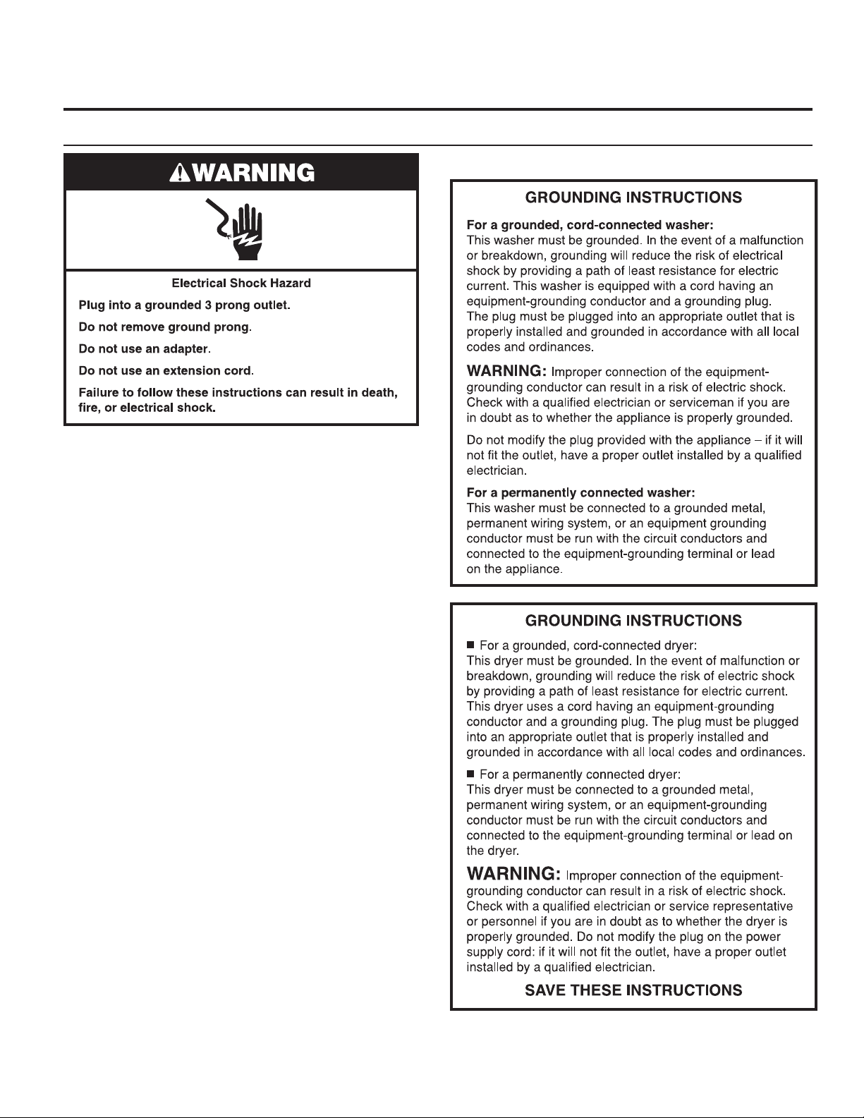
Stacked Washer/Gas Dryer Electrical Requirements
IMPORTANT: The washer/dryer must be electrically grounded
in accordance with local codes and ordinances or, in the
absence of local codes, with the National Electrical Code,
ANSI/NFPA 70, latest edition, or Canadian Electrical Code,
CSA C22.1. If codes permit and a separate ground wire is used,
it is recommended that a qualied electrical installer determine
that the ground path is adequate.
A copy of the above code standards can be obtained from:
National Fire Protection Association
One Batterymarch Park, Quincy, MA 02269
CSA International
8501 East Pleasant Valley Road
Cleveland, Ohio 44131-5575
n Do not ground to a gas pipe.
n Do not have a fuse in the neutral or ground circuit.
n A 120 volt, 60 Hz, AC only, 15 or 20 amp, fused electrical
circuit is required. A time-delay fuse or circuit breaker is also
recommended. It is recommended that a separate circuit
serving only this washer/dryer be provided.
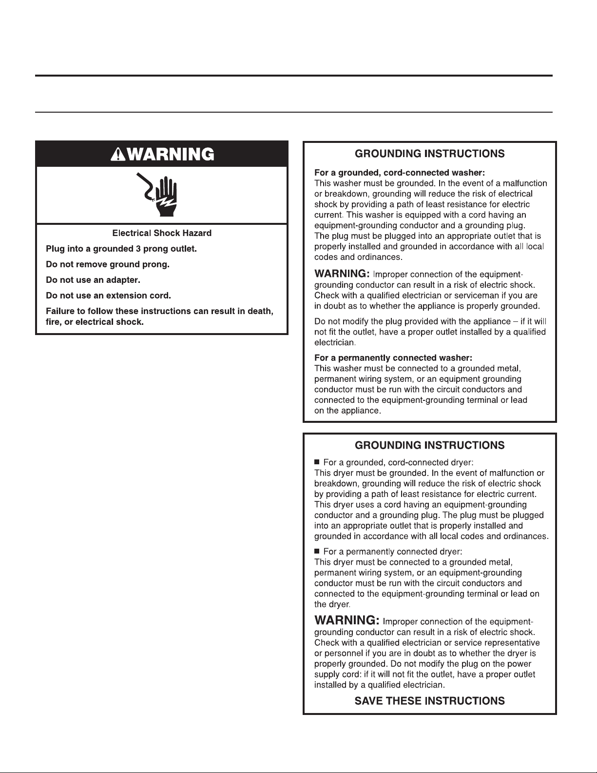
n This washer/dryer is equipped with a power supply cord
having a 3 prong grounding plug.
n To minimize the possibility of shock, the cord must be
plugged into a mating, 3 prong, grounding-type outlet,
grounded in accordance with local codes and ordinances.
If a mating outlet is not available, it is the personal
responsibility and obligation of the customer to have the
properly grounded outlet installed by a qualied electrician.
n If codes permit and a separate ground wire is used, it is
recommended that a qualied electrician determine that
the ground path is adequate.
n Check with a qualied electrician if you are not sure the
washer/dryer is properly grounded.
INSTALLATION REQUIREMENTS
Stacked Washer/Gas Dryer Grounding
9
STACKED WASHER/GAS DRYER
INSTALLATION REQUIREMENTS
Stacked Washer/Gas Dryer Gas Supply
IMPORTANT: Observe all governing codes and ordinances.
This installation must conform with all local codes and
ordinances. In the absence of local codes, installation must
conform with American National Standard, National Fuel Gas
Code ANSI Z223.1/NFPA 54 or CAN/CSA B149.
A copy of the above code standards can be obtained from:
National Fire Protection Association
One Batterymarch Park, Quincy, MA 02269
The design of this washer/dryer has been certied by CSA
International for use at altitudes up to 10,000 feet (3048 m)
above sea level at the B.T.U. rating indicated on the model/
serial plate. Burner input adjustments are not required when
the washer/dryer is operated up to this elevation.
When installed above 10,000 feet (3048 m), a four percent
(4%) reduction of the burner B.T.U. rating shown on the model/
serial plate is required for each 1,000 foot (305 m) increase in
elevation. For assistance when converting to other gas types
and/or installing above 10,000 feet (3048 m) elevation, contact
your local service company.
CSA International
8501 East Pleasant Valley Road
Cleveland, Ohio 44131-5575
10
STACKED WASHER/ELECTRIC DRYER
Stacked Washer/Electric Dryer Location
Selecting the proper location for your washer/dryer improves
performance and minimizes noise and possible washer “walk.”
Your washer/dryer can be installed in a basement, laundry
room, or recessed area. This washer/dryer is not intended
for installation in a mobile home or recreational vehicle.
See the “Drain System” section for more information.
Companion appliance location requirements should also
be considered.
IMPORTANT: Do not install or store the washer/dryer where
it will be exposed to the weather. Do not store or operate the
washer/dryer in temperatures at or below 32°F (0°C). Some
water can remain in the washer and can cause damage in
low temperatures. Proper installation is your responsibility.
INSTALLATION REQUIREMENTS
Stacked washer/electric dryer installation clearances
n The location must be large enough to allow the washer
and dryer doors to be fully opened.
n Additional spacing should be considered for ease of
installation and servicing. The doors open more than 180.°
The washer door is not reversible.
n Additional clearances might be required for wall, door,
and oor moldings.
n Additional spacing of 1" (25 mm) on all sides of the washer/
dryer is recommended to reduce noise transfer and to
improve spin-up performance of the washer.
n Companion appliance spacing should also be considered.
Recessed Area Installation Instructions
This washer/dryer may be installed in a recessed area. For
recessed area installations, minimum clearances can be found
on the warning label on the rear of the dryer.
The installation spacing is in inches and is the minimum
allowable. Additional spacing should be considered for ease
of installation, servicing, and compliance with local codes
and ordinances.
The dryer must be exhausted outdoors.
You will need:
n A water heater set to deliver 120°F (49°C) water to the
washer.
n A grounded electrical outlet located within 6 ft. (1.8 m) of
where the power cord is attached to the back of the washer.
See “Electrical Requirements.”
n Hot and cold water faucets located within 4 ft. (1.2 m)
of the hot and cold water ll valves, and water pressure
of 20–100 psi (137.9–689.6 kPa).
n A level oor with a maximum slope of 1" (25 mm) under
entire washer/dryer. Installing the washer/dryer on soft oor
surfaces, such as carpets or surfaces with foam backing,
is not recommended.
n A sturdy and solid oor to support the washer/dryer
with a total weight (water and load) of 450 lbs (204 kg).
n A oor drain under the bulkhead. Prefabricated bulkheads
with electrical outlets, water inlet lines, and drain facilities
should be used only where local codes permit.
11
STACKED WASHER/ELECTRIC DRYER
INSTALLATION REQUIREMENTS
Stacked Washer/Electric Dryer
Electrical Requirements
Stacked Washer/Electric Dryer GroundingWasher Electrical Requirements
n Do not have a fuse in the neutral or ground circuit.
n This washer/dryer is equipped with a power supply cord
having a 3 prong grounding plug.
n To minimize the possibility of shock, the cord must be
plugged into a mating, 3 prong, grounding-type outlet,
grounded in accordance with local codes and ordinances.
If a mating outlet is not available, it is the personal
responsibility and obligation of the customer to have the
properly grounded outlet installed by a qualied electrician.
n If codes permit and a separate ground wire is used, it is
recommended that a qualied electrician determine that
the ground path is adequate.
n Check with a qualied electrician if you are not sure
the washer is properly grounded.
12

Dryer Electrical Requirements
STACKED WASHER/ELECTRIC DRYER
INSTALLATION REQUIREMENTS
It is your responsibility:
n To contact a qualied electrical installer.
n To be sure that the electrical connection is adequate and in
conformance with the National Electrical Code, ANSI/NFPA
70 – latest edition and all local codes and ordinances.
The National Electrical Code requires a 4-wire power supply
connection for homes built after 1996 and dryer circuits
involved in remodeling after 1996.
A copy of the above code standards can be obtained from:
National Fire Protection Association, One Batterymarch
Park, Quincy, MA 02269.
n To supply the required 3 or 4 wire, single phase, 240 volt,
60 Hz., AC only electrical supply (or 3 or 4 wire, 120/208 volt
electrical supply, if specied on the serial/rating plate) on a
separate 30 amp circuit, fused on both sides of the line. A
time delay fuse or circuit breaker is recommended. Connect
to an individual branch circuit. Do not have a fuse in the
neutral or grounding circuit.
n Do not use an extension cord.
n If codes permit and a separate ground wire is used, it is
recommended that a qualied electrician determine that
the ground path is adequate.
Electrical Connection
To properly install your dryer, you must determine the type
of electrical connection you will be using and follow the
instructions provided for it here.
n This dryer is manufactured ready to install with a 3-wire
electrical supply connection. The neutral ground conductor
is permanently connected to the neutral conductor (white
wire) within the dryer. If the dryer is installed with a 4-wire
electrical supply connection, the neutral ground conductor
must be removed from the external ground connector (green
screw), and secured under the neutral terminal (center or
white wire) of the terminal block. When the neutral ground
conductor is secured under the neutral terminal (center
or white wire) of the terminal block, the dryer cabinet is
isolated from the neutral conductor.
n If local codes do not permit the connection of a neutral
ground wire to the neutral wire, see the “Optional 3-wire
connection” section.
n A 4-wire power supply connection must be used when the
appliance is installed in a location where grounding through
the neutral conductor is prohibited. Grounding through the
neutral is prohibited for (1) new branch-circuit installations
and (2) areas where local codes prohibit grounding through
the neutral conductor.
Electric Dryer Power Supply Cord
If using a power supply cord:
Use a UL Listed power supply cord kit marked for use with
clothes dryers. The kit should contain:
n A UL Listed 30 amp power supply cord, rated 240 volt
minimum. The cord should be type SRD or SRDT and be at
least 4 ft. (1.22 m) long. The wires that connect to the dryer
must end in ring terminals or “U” shaped spade terminals
with upturned ends.
n A UL Listed strain relief.
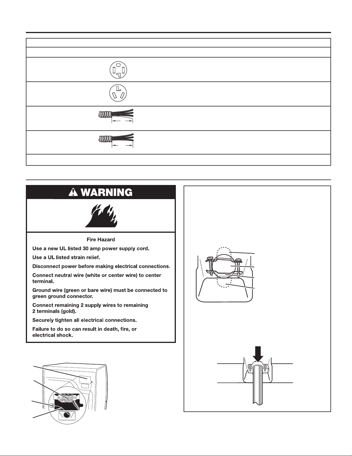
If your outlet looks like this:
Then choose a 4-wire power supply cord with ring
or spade terminals and UL Listed strain relief. The
4-wire power supply cord, at least 4 ft. (1.22 m)
long, must have four 10-gauge copper wires and
match a 4-wire receptacle of NEMA Type 14-30R.
4-wire
receptacle
(14-30R)
The ground wire (ground conductor) may be either
green or bare. The neutral conductor must be
identied by a white cover.
If your outlet looks like this:
Then choose a 3-wire power supply cord with ring
or spade terminals and UL Listed strain relief. The
3-wire power supply cord, at least 4 ft. (1.22 m)
long, must have three 10-gauge copper wires and
match a 3-wire receptacle of NEMA Type 10-30R.
3-wire
receptacle
(10-30R)
13

STACKED WASHER/ELECTRIC DRYER
INSTALLATION REQUIREMENTS
Dryer Direct Wire
Fire Hazard
Use 10 gauge copper wire.
Use a UL listed strain relief.
Disconnect power before making electrical connections.
Connect neutral wire (white or center wire) to center
terminal.
Ground wire (green or bare wire) must be connected
to green ground connector.
Connect remaining 2 supply wires to remaining
2 terminals (gold).
Securely tighten all electrical connections.
Failure to do so can result in death, re, or
electrical shock.
If connecting by direct wire:
Power supply cable must match power supply (4-wire or 3-wire)
and be:
n Flexible armored cable or nonmetallic sheathed copper
cable (with ground wire), covered with exible metallic
conduit. All current-carrying wires must be insulated.
n 10 gauge copper wire (do not use aluminum).
n At least 5 ft. (1.52 m) long.
14
DRYER VENTING REQUIREMENTS
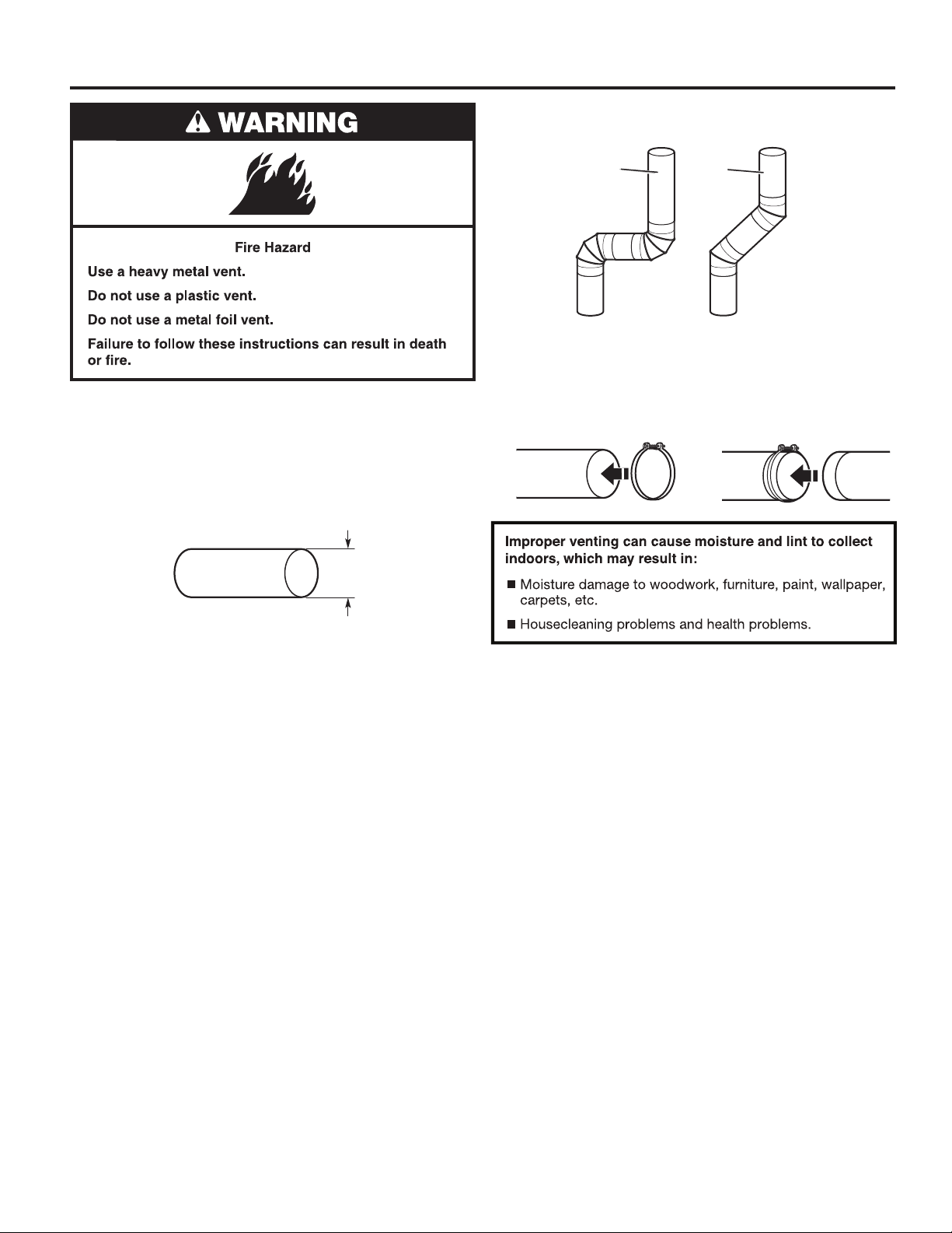
Elbows:
n 45° elbows provide better airow than 90° elbows.
WARNING: To reduce the risk of re, this dryer MUST BE
EXHAUSTED OUTDOORS.
IMPORTANT: Observe all governing codes and ordinances.
Dryer exhaust must not be connected into any gas vent,
chimney, wall, ceiling, attic, crawlspace, or a concealed space
of a building. Only rigid or exible metal vent shall be used
for exhausting.
4"
(102 mm)
Good
Better
Clamps:
n Use clamps to seal all joints.
n Exhaust vent must not be connected or secured with
screws or other fastening devices that extend into interior
of duct and catch lint. Do not use duct tape.
4" (102 mm) heavy, metal exhaust vent
n Only a 4" (102 mm) heavy, metal exhaust vent and clamps
may be used.
n Do not use plastic or metal foil vent.
Rigid metal vent:
n Recommended for best drying performance and to avoid
crushing and kinking.
Flexible metal vent: (Acceptable only if accessible to clean)
n Must be fully extended and supported in nal dryer location.
n Remove excess to avoid sagging and kinking that may
result in reduced airow and poor performance.
n Do not install in enclosed walls, ceilings, or oors.
n The total length should not exceed 7
NOTE: If using an existing vent system, clean lint from entire
length of the system and make sure exhaust hood is not
plugged with lint. Replace plastic or metal foil vents with rigid
metal or exible metal vents. Review “Vent System Chart” and
if necessary, modify existing vent system to achieve best drying
performance.
3
⁄4 ft. (2.4 m).
15
DRYER VENTING REQUIREMENTS
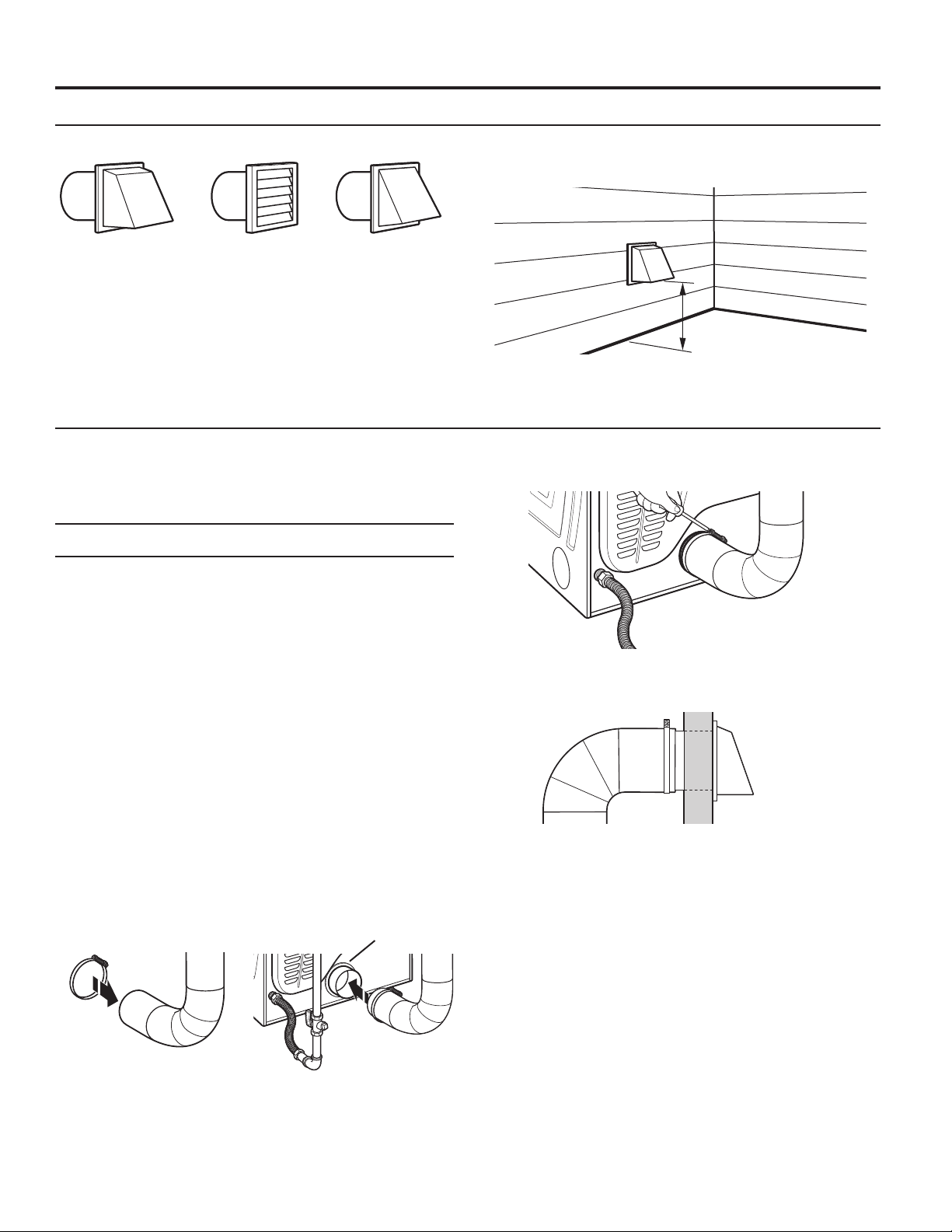
Vent Hoods
4" (102 mm) Diameter Exhaust Hoods
Exhaust hood must be at least 12" (305 mm) from the ground
or any object that may be in the path of the exhaust (such as
owers, rocks, bushes, or snow).
Box hood Louvered hood Angled hood
Vent System Length
Maximum Vent Length/Vent Connection
Maximum length of vent system depends upon the type of vent
used, number of elbows, and type of exhaust hood.
Vent System Chart (Rigid Metal Vent )
No. of Box and Angled
90˚ Turns Louvered Hood Hood
0 64 ft. (19.5 m) 58 ft. (17.7 m)
1 54 ft. (16.5 m) 48 ft. (14.6 m)
2 44 ft. (13.4 m) 38 ft. (11.6 m)
3 35 ft. (10.7 m) 29 ft. (8.8 m)
4 27 ft. (8.2 m) 21 ft. (6.4 m)
For vent systems not covered by the vent specication chart,
see your parts distributor.
Provision must be made for enough air for combustion and
ventilation (check governing codes and ordinances). See
“Recessed Area Installation Instructions” in the “Stacked
Washer/Gas Dryer Location” and “Stacked Washer/Electric
Dryer Location” sections.
A 4" (102 mm) outlet hood is preferred. However, a 2
(64 mm) outlet exhaust hood may be used. A 2
outlet creates greater back pressure than other hood types.
For permanent installation, a stationary vent system is required.
Connect Vent
1. If connecting to existing vent, make sure the vent is clean.
2. Using a 4" (102 mm) clamp, connect vent to exhaust outlet
in dryer.
1
⁄2"
1
⁄2" (64 mm)
Vent collar
12" min.
(305 mm)
3. Tighten hose clamp with Phillips screwdriver.
4. Make sure the vent is secured to exhaust hood
with a 4" (102 mm) clamp.
5. Move dryer into nal position. Do not crush or kink vent.
Make sure dryer is level.
NOTE: Do not remove vent collar.
16
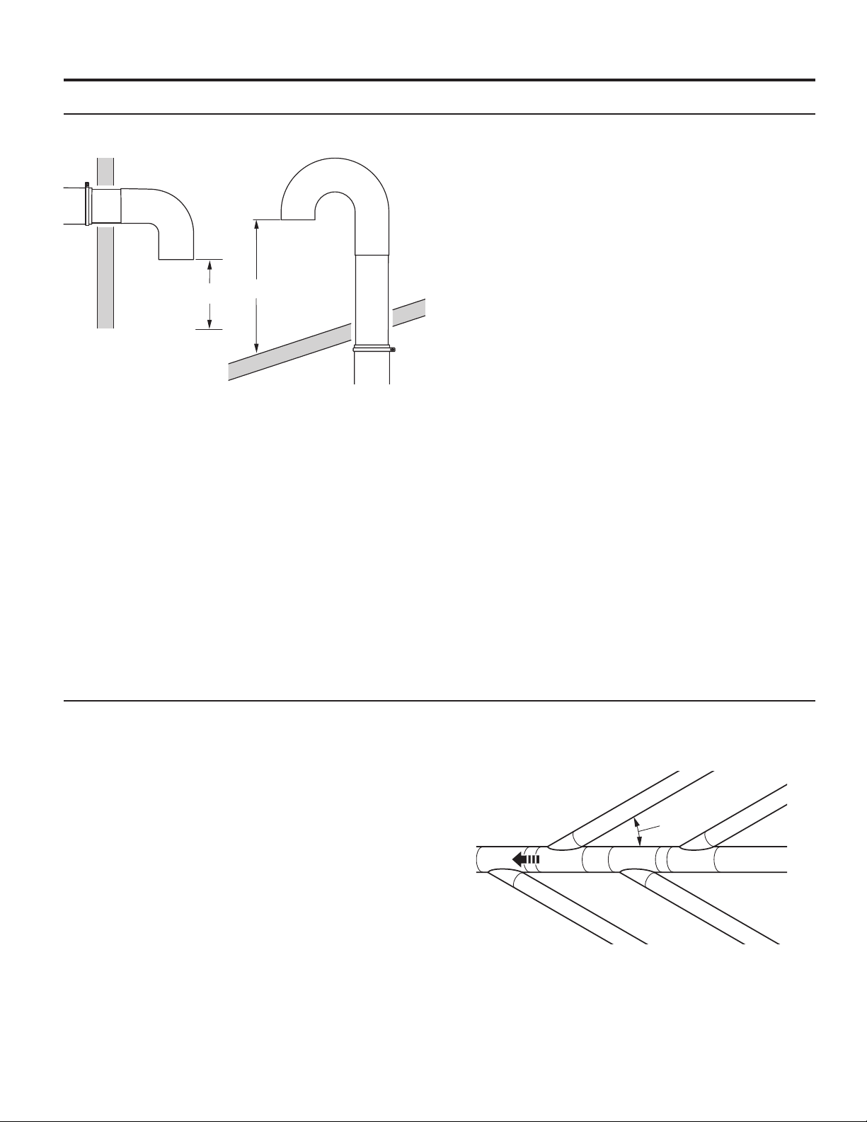
If an Exhaust Hood Cannot Be Used
The outside end of main vent should have a sweep elbow
directed downward.
DRYER VENTING REQUIREMENTS
12" min.
(305 mm)*
* Minimum clearance above
any accumulation of snow,
ice, or debris such as leaves
If main vent travels vertically through the roof, rather than
through wall, install a 180° sweep elbow on end of vent at least
2 ft. (610 mm) above surface of roof.
The opening in wall or roof shall have a diameter 1⁄2" (13 mm)
larger than vent diameter. Vent should be centered in opening.
Do not install screening over end of vent for best performance.
24" min.
(610 mm)
Multiple Dryer Venting
A main vent can be used for venting a group of dryers. The
main vent should be sized to remove 200 CFM of air per dryer.
Large-capacity lint screens of proper design may be used in
main vent if checked and cleaned frequently. The room where
the dryers are located should have make-up air equal to or
greater than CFM of all the dryers in the room.
Back-draft Damper Kit, Part No. 3391910, is available from
your distributor and should be installed in the vent of each
dryer to keep exhausted air from returning into dryers and to
keep exhaust in balance within main vent. Unobstructed return
air openings are required.
Each vent should enter the main vent at an angle pointing in
the direction of the airow. Vents entering from the opposite
side should be staggered to reduce the exhausted air from
interfering with the other vents.
30˚ max.
air ow
The maximum angle of each vent entering the main vent should
be no more than 30.°
17
DRYER GAS SUPPLY REQUIREMENTS
Type of Gas
This dryer is equipped for use with natural gas. It is certied
by UL for use with propane gas with appropriate conversion.
No attempt shall be made to convert dryer from gas specied
on serial/rating plate for use with a different gas without
consulting the serving gas supplier. Conversion must be done
by a qualied service technician.
Gas conversion kit part numbers are listed on gas valve
burner base.
Gas Supply Line
Recommended Method
Provide a gas supply line of 1⁄2" (13 mm) rigid (IPS) pipe
to dryer location. Pipe joint compounds that resist action
of propane gas must be used. Do not use TEFLON
With propane gas, piping or tubing size can be 1⁄2" (13 mm)
minimum. Usually, propane gas suppliers determine size and
materials used in the system.
®†
tape.
Gas Supply Pressure Testing
A 1/8" (3 mm) NPT minimum plugged tapping, accessible for
gauge testing, must be installed immediately downstream of
the installed shut-off valve to the dryer (as shown above). The
dryer must be disconnected from the gas supply piping system
during any pressure testing of the system at test pressures in
excess of 1/2" psig (352 kg/m
2
).
Alternate Method
The gas supply may also be connected using 3⁄8" (10 mm)
approved copper or aluminum tubing. If the total length of
the supply line is more than 20 ft. (6.1 m), larger tubing will
be required.
If using natural gas, do not use copper tubing. Pipe joint
compounds that resist action of type of gas supplied must
be used.
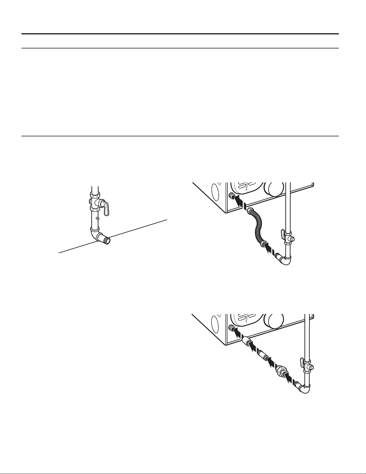
Flexible Metal Appliance Connector
It is recommended that a new exible stainless steel gas line,
design-certied by CSA International, be used for connecting
the dryer to the gas supply line (the gas pipe which extends
through the lower rear of the dryer is provided with 3⁄8"
[10 mm] male pipe thread).
NOTE: Do not kink or damage the exible stainless steel gas
line when moving the dryer.
Rigid Pipe Connection
The rigid pipe connection requires a combination of pipe ttings
to obtain an in-line connection to dryer.
Shut-off valve required
The supply line must be equipped with a manual shut-off valve
installed within 6 ft. (1.8 m) of dryer in accordance with National
Fuel Gas Code, ANSI Z223.1. This valve should be located in
same room as dryer. It should be in a location that allows ease
of opening and closing. Do not block access to shut-off valve.
†®TEFLON is a registered trademark of Chemours.
18
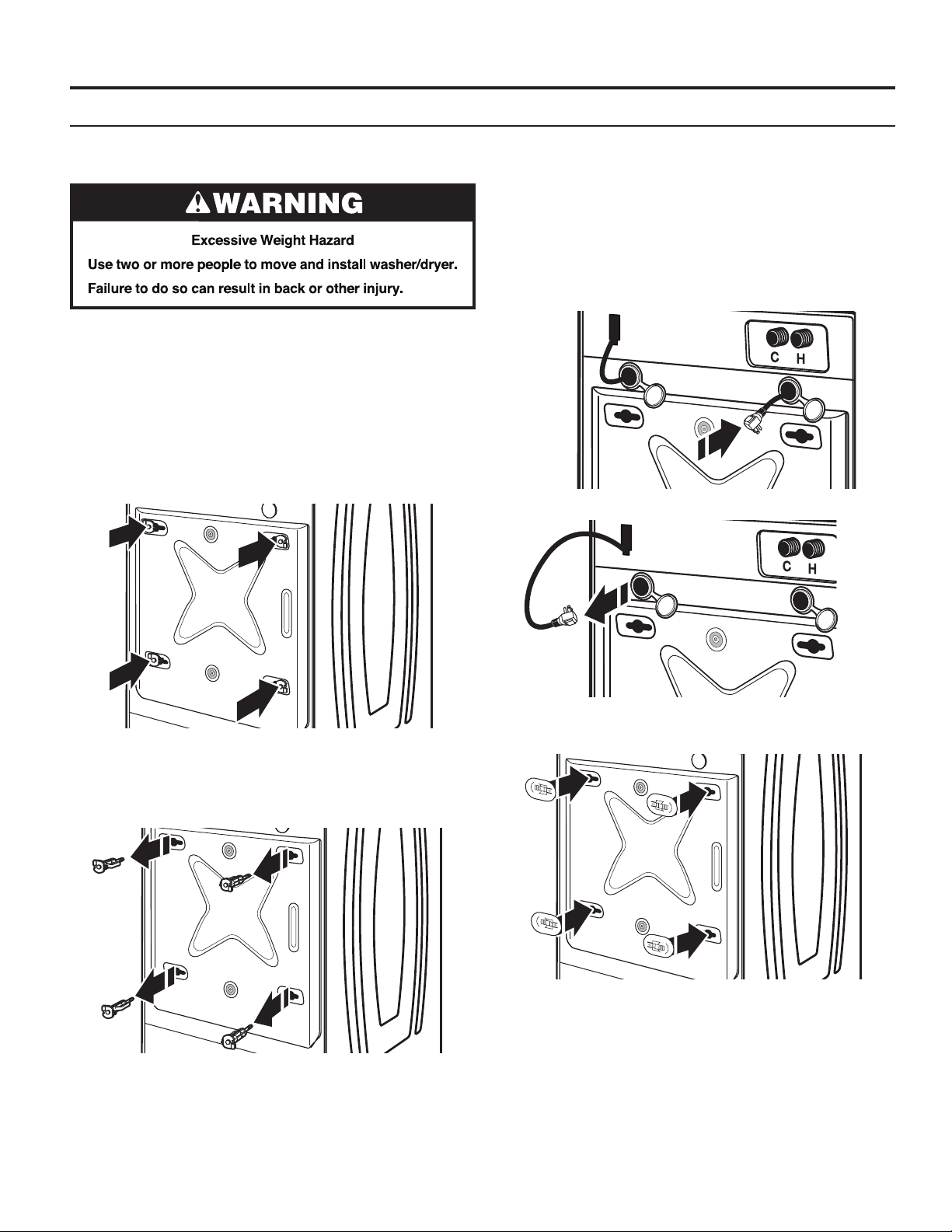
Remove Transport System
INSTALLING STACKED WASHER/DRYER
NOTE: Slide washer/dryer onto cardboard or hardboard before
moving to avoid damaging oor covering.
IMPORTANT: Position the washer/dryer so that the rear of
the washer is within approximately 3 ft. (900 mm) of its nal
location.
There are four shipping bolts in the rear panel of the washer
that support the suspension system during transportation.
These bolts also retain the power cord inside the washer
until the bolts are removed.
1. Keep the washer/dryer in the upright position while removing
the shipping bolts.
2. Using a 1/2" (13 mm) wrench, loosen each of the bolts.
4. Models with separate washer power cords: Push the power
cord plug into the opening on the right side of the rear panel
and pull the power cord through the opening on the left side
of the rear panel and close holes with the attached cap. Do
not pull plug end of power cord through the right side hole.
NOTE: To avoid damage to internal washer parts or the
power cord, if the cord does not pull out of the washer rear
panel easily, do not force it. Remove the washer rear panel
and guide the power cord around the obstruction and out
the hole on the left side of the rear panel.
3. Once the bolt is loose, move it to the center of the hole
and completely pull out the bolt, including the plastic spacer
covering the bolt. Once all four bolts are removed, discard
the bolts and spacers.
5. Close the bolt holes with the four transport bolt hole plugs.
IMPORTANT: If the washer/dryer is to be transported, call
your product distributor or installer. To avoid suspension and
structural damage, your washer/dryer must be properly set up
for relocation by a trained professional.
19

INSTALLING STACKED WASHER/DRYER
Connect Inlet Hoses
Insert new hose washers (supplied) into each end of the inlet
hoses. Firmly seat the washers in the couplings.
Connect Inlet Hoses to Washer
1. Attach the cold water hose to the washer’s cold water inlet
valve. Screw on coupling by hand until it is seated on
the washer.
Washer
Coupling
Connect Inlet Hoses to Water Faucets
Make sure the washer drum is empty.
1. Attach a hose to the hot water faucet. Screw on coupling
by hand until it is seated on the washer.
2. Attach a hose to the cold water faucet. Screw on coupling
by hand until it is seated on the washer.
3. Using pliers, tighten the couplings with an additional
two-thirds turn.
2. Attach the hot water hose to the washer’s hot water inlet
valve. Screw on coupling by hand until it is seated on
the washer.
3. Using pliers, tighten the couplings with an additional
two-thirds turn.
NOTE: Do not overtighten. Damage to the valve can result.
4. Turn on the water faucets completely and check for leaks.
NOTE: Do not overtighten or use tape or sealants on the valve.
Damage to the valves can result.
Clear Water Lines
n Run water through both faucets and inlet hoses, into a
laundry tub, drainpipe, or bucket, to get rid of particles
in the water lines that might clog the inlet valve screens.
n Check the temperature of the water to make sure that the
hot water hose is connected to the hot water faucet and that
the cold water hose is connected to the cold water faucet.
20
NOTE: Replace inlet hoses after 5 years of use to reduce the
risk of hose failure. Record hose installation or replacement
dates on the hoses for future reference.
Periodically inspect and replace hoses if bulges, kinks, cuts,
wear, or leaks are found.

INSTALLING STACKED WASHER/DRYER
Route Drain Hose
Proper routing of the drain hose avoids damage to your oor
due to water leakage. Read and follow these instructions.
Remove drain hose from the washer drum
1. Using locking pliers, squeeze hose clamp tabs together
and insert over the end of the drain hose.
2. Slide the drain hose onto the washer connection.
3. Once the drain hose is in place, release the pliers.
4. The washer drain system can be installed using a oor drain,
wall standpipe, oor standpipe, or laundry tub.
Laundry tub drain or standpipe drain
Connect the drain hose form to the corrugated drain hose.
Snap either end of the drain hose form to the
drain hose at the point where the corrugation
begins.
Secure Drain Hose
1. Drape the power cord over the washer top.
2. Move the washer to its nal location.
3. Place the drain hose
in the laundry tub or
standpipe as shown.
4. Secure the drain hose
using the supplied beaded
tie strap.
41/2"
(114 mm)
41/2"
(114 mm)
Bend drain hose over drain hose form and
snap into place.
NOTE: Hose must not extend more than 1"
(25 mm) past the end of the U bend.
To keep drain water from going back into the washer:
n Do not straighten the drain hose; do not force excess
drain hose into standpipe. Hose should be secure, but
loose enough to provide a gap for air.
n Do not lay excess hose on the bottom of the laundry tub.
Floor drain
You may need additional parts. See “Alternate Parts.”
5. If the washer faucets and the
drain standpipe are recessed, put
the hooked end of the drain hose
in the standpipe as shown.
NOTES:
n Do not force excess drain hose
back into the rear of the washer.
n To avoid siphoning, do not
seal the drain hose into
the standpipe.
21

WASHER DRAIN SYSTEM
(762 mm)
The washer can be installed using the standpipe drain system
(oor or wall), the laundry tub drain system, or the oor drain
system.
Standpipe drain system – wall or oor
The standpipe drain requires a minimum diameter standpipe
of 2" (51 mm). The minimum carry-away capacity can be no
less than 10 gal. (38 L) per minute.
Wall
The top of the standpipe must be at least 30" (762 mm) high
and no higher than 96" (2.4 m) from the bottom of the washer.
Floor
Laundry tub drain system
The laundry tub needs a minimum 20 gal. (76 L) capacity.
The top of the laundry tub must be at least 30" (762 mm)
above the oor.
30
"
Floor drain system
The oor drain system requires a siphon break that may be
purchased separately.
The siphon break (Part Number 285834) must be a minimum
of 28" (710 mm) from the bottom of the washer. Additional
hoses might be needed.
30
" min.
(762 mm)
Siphon
break
28
"
(710 mm)
22
ELECTRIC DRYER ELECTRICAL CONNECTIONS
Electrical Connection Options
If your location has: And you will be connecting to: Go to Section
4-wire receptacle A UL Listed, Power supply cord,
(NEMA Type 14-30R) 120/240 volt minimum, 30 amp 4-wire connection
dryer power supply cord*
3-wire receptacle A UL Listed, Power supply cord,
(NEMA type 10-30R) 120/240 volt minimum, 30 amp 3-wire connection
dryer power supply cord*
4-wire direct A fused disconnect Direct wire,
or circuit breaker box* 4-wire connection
3-wire direct A fused disconnect Direct wire,
or circuit breaker box* 3-wire connection
* If local codes do not permit the connection of a cabinet-ground conductor to the neutral wire, go to “Optional, 3-wire connection” section.
Power Supply Cord
5"
(127 mm)
3½"
(89 mm)
Power supply cord strain relief:
1. Disconnect power.
2. Remove the hold-down screw and terminal block cover.
D
C
B
A. Neutral ground wire
B. External ground
conductor screw
C. Center terminal
block screw
D. Terminal block cover
and hold-down screw
n Remove the screws from a 3/4" (19 mm) UL Listed
strain relief. Put the tabs of the two clamp sections into
the hole below the terminal block opening so that one
tab is pointing up and the other is pointing down, and
hold in place.
Tighten strain relief screws enough to hold the two clamp
sections together.
A
A. Strain relief tab
pointing up
B. Hole below terminal
B
C
D
block opening
C. Clamp section
D. Strain relief tab
pointing down
n Put power supply cord through the strain relief. Be
sure that the wire insulation on the power supply
cord is inside the strain relief. The strain relief should
have a tight t with the dryer cabinet and be in a
horizontal position. Do not further tighten strain relief
screws at this point.
A
3. Install power supply cord strain relief.
23
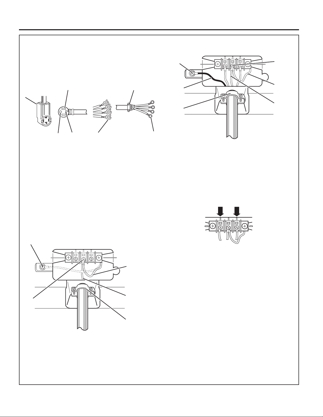
ELECTRIC DRYER ELECTRICAL CONNECTIONS
Power supply cord,
4-wire connection:
IMPORTANT: A 4-wire connection is
required where local codes do not permit
the use of 3-wire connections.
B
A
C
D
A. 4-wire receptacle (NEMA type 14-30R)
B. 4-prong plug
C. Ground prong
D. Neutral prong
E. Spade terminals with upturned ends
F.
3/4"
(19 mm) UL Listed strain relief
G. Ring terminals
1. Remove center terminal block screw.
2. Remove neutral ground wire from
external ground conductor screw.
Connect neutral ground wire and
the neutral wire (white or center wire)
of power supply cord under center
terminal block screw. Tighten screw.
E
3. Connect ground wire (green or bare) of power supply
cord to external ground conductor screw. Tighten screw.
A
F
G
B
C
A. External ground conductor screw
B. Ground wire (green or bare) of power supply cord
3/4"
(19 mm) UL Listed strain relief
C.
D. Center terminal block screw
E. Neutral ground wire
F. Neutral wire (white or center wire)
D
E
F
4. Connect the other wires to outer terminal block screws.
Tighten screws.
A
B
A. External ground conductor screw – Dotted line shows
position of NEUTRAL ground wire before being moved
to center terminal block screw.
B. Center terminal block screw
C. Neutral ground wire
D. Neutral wire (white or center wire)
E.
3/4"
(19 mm) UL Listed strain relief
5. Tighten strain relief screws.
C
6. Insert tab of terminal block cover into slot of dryer
rear panel. Secure cover with hold-down screw.
7. You have completed your electrical connection.
D
E
24

ELECTRIC DRYER ELECTRICAL CONNECTIONS
Power supply cord,
3-wire connection:
B
A
C
A. 3-wire receptacle (NEMA type 10-30R)
B. 3-wire plug
C. Neutral prong
D. Spade terminals with upturned ends
E. 3/4" (19 mm) UL Listed strain relief
F. Ring terminals
G. Neutral (white or center wire)
A
B
Use where local codes permit connecting
cabinet-ground conductor to neutral wire.
1. Loosen or remove center terminal block screw.
D
E
2. Connect neutral wire (white or center wire) of power
supply cord to the center terminal screw of the terminal
block. Tighten screw.
3. Connect the other wires to outer terminal block screws.
Tighten screws.
G
F
4. Tighten strain relief screws.
C
5. Insert tab of terminal block cover into slot of dryer
rear panel. Secure cover with holddown screw.
6. You have completed your electrical connection.
D
E
A. External ground conductor screw
B. Neutral ground wire
C. Center terminal block screw
D. Neutral wire (white or center wire)
E. 3/4" (19 mm) UL Listed strain relief
25
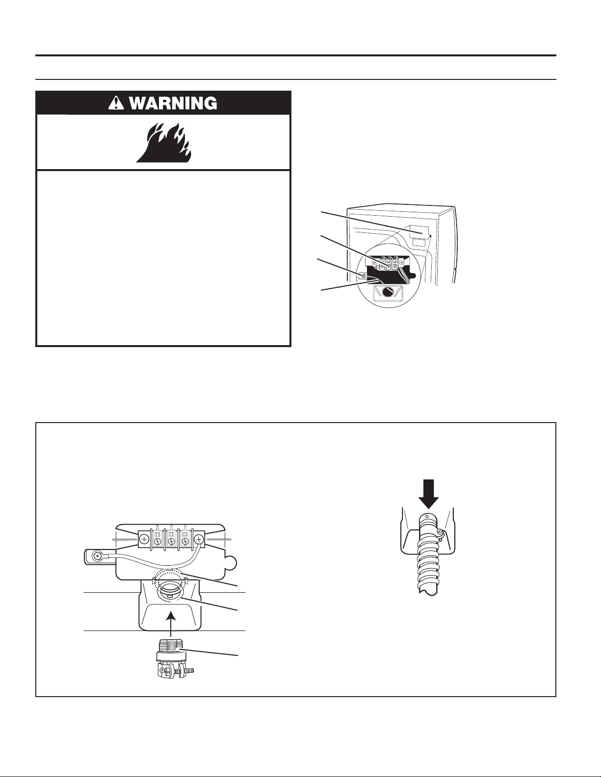
ELECTRIC DRYER ELECTRICAL CONNECTIONS
Direct Wire Method
Direct wire cable must match power supply (4-wire or 3-wire)
and be:
n Flexible armored cable or nonmetallic sheathed copper
cable (with ground wire), protected with exible metallic
conduit. All current-carrying wires must be insulated.
n 10 gauge copper wire (do not use aluminum).
n At least 5 ft. (1.52 m) long.
Fire Hazard
Use 10 gauge copper wire.
Use a UL listed strain relief.
Disconnect power before making electrical connections.
Connect neutral wire (white or center wire) to center
terminal.
Ground wire (green or bare wire) must be connected
to green ground connector.
Connect remaining 2 supply wires to remaining
2 terminals (gold).
Securely tighten all electrical connections.
Failure to do so can result in death, re, or
electrical shock.
1. Disconnect power.
2. Remove hold-down screw and terminal block cover.
D
C
B
A
3. Install direct wire strain relief.
4. Complete installation following instructions for your type
of electrical connection:
• 4-wire (recommended method)
• 3-wire (if four-wire is not available)
A. Neutral ground wire
B. External ground
conductor screw
C. Center terminal
block screw
D. Terminal block cover
and hold-down screw
Direct wire strain relief:
n Unscrew the removable conduit connector and
any screws from a 3/4" (19 mm) UL Listed strain
relief. Put the threaded section of the strain relief
through the hole below the terminal block opening.
Reaching inside the terminal block opening, screw
the removable conduit connector onto the strain
relief threads.
A
B
C
n Put direct wire cable through the strain relief. The strain
relief should have a tight t with the dryer cabinet and
be in a horizontal position. Tighten strain relief screw
against the direct wire cable.
A. Removable conduit connector
B. Hole below terminal block opening
C. Strain relief threads
26
 Loading...