


IMPORTANT:
Part No, 8316558 Rev, A
Read and save
these instructions
IMPORTANT
Installer:Leave InstallationInstructions
withthe owner.
Owner: Keep InstallationInstructionsfor
futurereference.
Save InstallationInstructionsforlocal
electricalinspector'suse.
www.whirlpool.oom
COMMERCIAL
DRYER
ELECTRIC
120-volt, 60 Hz
120/240-volt, 60 Hz
COMMERCIAL
LAUNDRY
PRODUCTS
]B 'ore you start...
Your safety and the safety of others are very important.
We have provided many important
safety messages in this manual and
on your appliance. Always read and
obey all safety messages.
This is the safety alert symbol.
This symbol alerts youto
potential hazards that can kill
or hurt you and others.
All safety messages will follow the
safety alert symbol and either the word
"DANGER" or WVARNING". These
words mean:
WARNING:Foryoursafetythe
informationinthis manualmustbe
followedto minimizetheriskoffire or
explosionortopreventproperty
damage,pemonalinjuryordeath.
You can be killed or seriously
injured if you don't immediately
follow instructions.
You can be killed or seriously
injured If you don't follow
instructions.
All safety messages will tell you
what the potential hazard is, tell you
how to reduce the chance of injury,
and tell you what can happen if the
instructions are not followed.
• Donottoncbanyelectrical
switch;donotusaanyphonein
yourbuilding.
• Cleartheroom,buildingorareaof
all occupants.
• Immediatelycallyourgassupplier
-- Donotstoreorusegasoline,
orotherflammablevaporsandliquids
inthevicinityofthis oranyother
appliance.
--WHAT TODOIFYOUSMELLGAS:
• Donottrytolight anyappliance.
froma neighbor'sphone.Follow
thegassuppliersinstructions.
• ifyoucannotreachyourgas
supplier,callthe firedepnrbnent.
-- Installationandservicemustbe
donebya qualifiedinstaller,
serviceagencyorthegassupplier.
It is your
responsibility to:
Ol_rve all governing cedes and
ordinances.
Check code r_:lulmments: Some codes
Explosion Hazard
Keep flammable materials and
vapors, such as gasoline, away
from dryer.
Place dryer at least 18 inches
(45.8 cm) above the floor for a
garage installation.
Failure to do so can result in death,
explosion, or fire.
aGnS
Postgdswarning in o prominent
locollon.
itisrecommended that the operator
post, ina prominent location,
instructionsfor the customer's use in the
event the customer smeltsgas. This
informationshould be obtained from
your local gas supplier.
limit or do not permit installation of clothes
dryers in garages, closets, mobile homes or
sleeping quarters. Contact your local
building inspector,
Comply with the installation specifications
and dimensions.
Consider spacing requirements for
companion appliances.
Make sure you have everything necessary
for proper installation,
Properly install dryer.
Contact a qualified installer to insure that
the electrical and gas installcfllons meet all
national and local codes and ordinances.
Exhaust to _Jh:kx_s: Dryer must be
exhausted outdoors to prevent exposure to
harmful substances in the gas fuels.
Note: The dryer must not be installed In an
area where it will be exposed to water
and/or weather,
IMPORTANTSAFETYINSlRUCE)NS
WARNING_ Tomclu_ '1_ dskofI_,
et_hi¢ shock, _ inlu_ to I_rsom wi_m
mir1_lyour c_llcmce, foEow bl:_¢
precautions,including the following:
1. Read all instructionsbefore usingthe
appliance.
2. DO not dry articlesthat have been
previously cleaned in,washed in,
soaked in, or spotted with gasoline,
dry-cleaning solvents, or other
flammable or explosive substances, as
they give off vapaurs that could ignite
Or exp--.
3. DO not allow childrento play on orin
the appliance. Close supervisionof
children isnecessary when the
appliance is used near children.
4. Before the appliance isremoved from
service or discarded, remove the dear
to the drying compartment,
5. Do not reach into the appliance ifthe
drum ismoving.
6. Do not installorstore this appliance
where itwill be exposed to the
weather,
7. Do not tamper with cOnITOIS,
8. Do not repair or replace any part of
the appliance or affempt any
servicing unless specifically
recommended inthe user-
maintenance instTuctionsor in
pu_ user-repair Instructions that
you understand and have the skillsto
carry out,
9. Do not use fabric softeners or products
to eliminate static unless
recommended by the manufacturer
of the fabric softener or product.
10. Do not use heat to dry articles
containing foam rubber or similarly
textured rubber-like materials,
11. Clean Ilntscreen before or after each
load.
12. Keep area around the exhaust
opening and adjacent su#ounding
areasflee from the accumulation of
lint,dust, and dirt.
13.The interiorof the appliance and
exhaust duct should be cleaned
periodically by qualified service
personnel
14.Do not place items exposed to
cooking oils inyour dryer. Items
contaminated with cooking oilsmay
contribute to a chemical reaction the
could cause a load to catch fire,
SAVETHESEINSTRUCTIONS
Post this warning in a prominent
location.
FORYOURSAFETY
DOnot storeor use gasoline or
other flammable vapors and liquids
In the vicinity of thisor any other
appliances.
Page 2
The console houses the accumulator
timer with actuating arm and button,
The timer is set to provide 45 minutes
(4 pins) of drying time when activated
by the coin slide. Timer cams for
30- minute (6 pins) and 60-minute
(3 pins) drying times are included in
the parts bag,
The coin-slide mechanism, control
panel lock and key, and coin-box leck
and key are not included and are
available from usual industry sources.
To change to a
30- or 60-minute
timingcam
(for mechanical timer
models only)
Electrical Shock Hazard
Disconnect power before
making cam changes.
Failure to do so can result in
death or electrical shock.
Each coin-operated dryer is
equipped with a 45-minute timer
cam that provides 45 minutes of
drying time when activated by the
coin slide.
You can install the 30-minute or
60-minute timing cam (shipped with
drye0 as follows:
I. Unlock meter case. Reach into
control panel area,
2. Turn the timing cam by hand until
the "V" -shaped notch lines up
below the ratchet tooth,
ralchet looth smlng cam
Une u lug
clear
ratchet hub
tooth, down
ddve
4. Place new cam (hub side down)
over clock shaft. Line up fiat side of
shaft with flat side of cam hole,
Check that drive lug is in place.
5. Turn cam until "V" -shaped notch
lines up with ratchet tooth,
6. Press cam down in place on motor
shaft, Make sure that "V _ -shaped
notch clears the ratchet tooth.
7. Close and lock the meter case,
Exhaust
requirements
Fire Hazard
Use a heavy metal vent.
0o not use a plastic vent.
Do not use a metal foil vent.
Failure to do so can result In
death or fire.
Do not use non-metal flexible vent,
metal vent that is smaller than four
inches in diameter or exhaust hoods with
magnetic latches.
The dryer must be exhausted outdoors.
Do not exhaust dryer into a gas vent,
chimney, wall, ceiling, or concealed
space of a building.
Do not install flexible vent in enclosed
walls, ceilings or floors,
If using an existing exhaust system, cleon
lint from entire length of exhaust system.
Make sure exhaust hood is not plugged
with lint.
The exhaust system should be inspected
and cleaned yearly,
Replace any plastic or metal foil exhaust
vent with rigid metal or flexible metal
vent.
Use4"110.2cm) ventclamps to
secureventsystem.
exhaust airl_w
Metalflexibleventmust be fully
extended and supportedwhen the
dryerisinitsfinalposition.DO NOT
KINKOR CRUSH THEVENT,The metal
flexibleventmustbe complelely
open to allow adequate exhaust air
to flow.
Allow as much room as possible
when using elbows or making turns.
Bend vent gradually to avoid kinking.
Remove excess flexible vent to avoid
sagging and kinking that may result in
reduced air flow,
Exhaustouflet islocatedatthe
centerofthe bottom dryerback.
The exhaustventcan be routedup,
down, left,fight,behindthe dryeror
straightoutthe back ofthedryer.
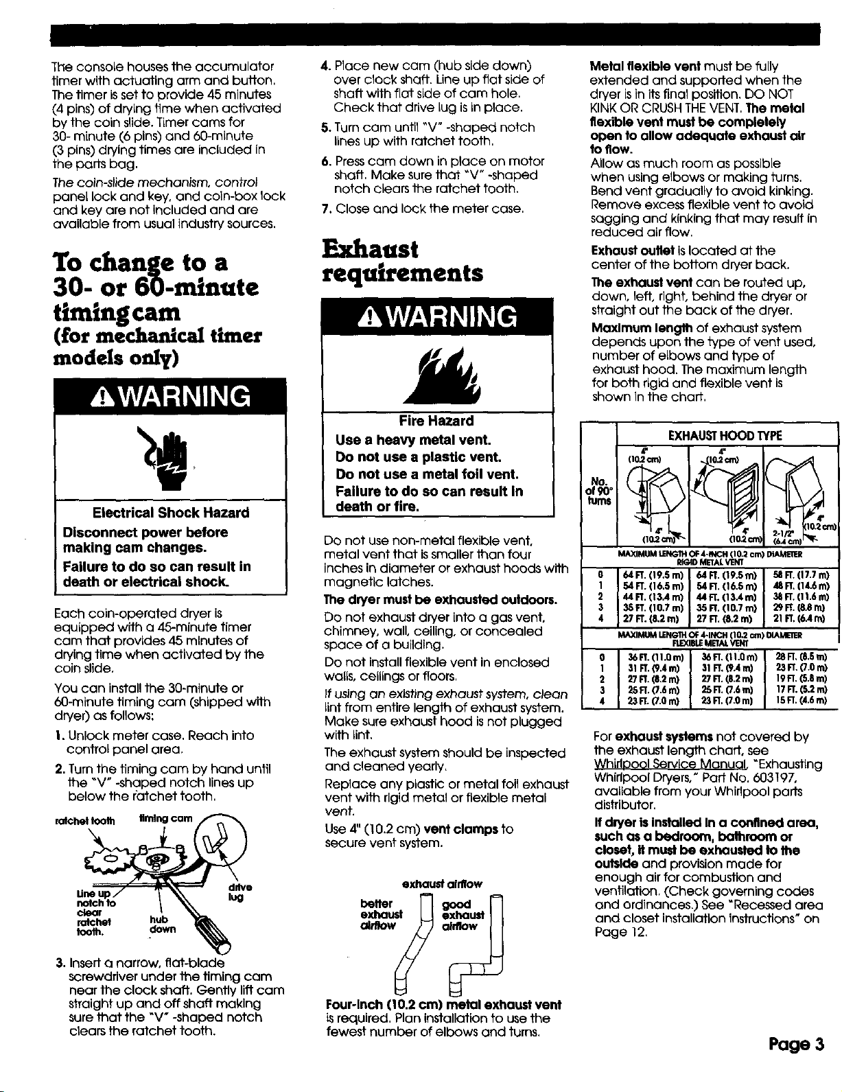
Maxlmum lengthofexhaustsystem
depends upon thetype ofventused,
number ofelbows and typeof
exhausthood.The maximum length
forboth rigidand flexibleventis
shown inthe chart,
EXHAUSTHOOD TYPE
(lO.2cm)
MAXIMUMLENGTHOF4-R4C1"1(I 0,2cm) _R
O 64 FT. (19.S m) 64 FT. (19.S m) 58 FT.(17.7 m)
1 54 FT. (16.S m) 54 FT,(|6.S m) 48 FT.(14.6 m)
2 44 FT.(r3.4 m) 44 FT. (13.4 m) 38 FT.(11.6 m)
3 35 FT. (10.7 m) 35 FT.(10.7 m) 29 FT.(8.8 m)
4 27 FT. (8.2 rn) 27 FT. (8.2 m) 21 FT.(6.4 m)
MAXIMUMLEFU_IHOf 4-INCH 110.2c:m)1_4AME11ER
31 FT.(9.4 n0 31FT, (9.4 m) 23 FT.(7.0 m)
27 FT.(8.2 m) 27 FT.(S.2 m) 19R. (S.S m)
25R, (7.6 m) _5 FT.(7.6 m) 17 FT.(5.2 m)
36 FT.(11.0 m) 36 FT.(11.Qm) 28 FT,[S,5 m)
23 FT.(7.0 m) 23 FT.(7.0 m] 15FT.(4.6 m)
RIGIDMETALVENT
FLEXIBLEMETALVENT
Forexhaust systems notcoveredby
theexhaustlengthchart,see
WhirlooolServiceManual °Exhausflng
WhirlpoolDryers/PartNo.603197,
avaliablefrom yourWhirlpoolparts
distributor,
If dryer is Installed In a confined area,
such as a bedroom, bothroom or
closet, It must be exhausted to the
outside and provision made for
enough air for combustion and
ventilation, (Check governing codes
and ordinances.) See "Recessed area
and closet installation instructions" on
Page 12,
3. Insert a narrow, fiat-blade
screwdriver under the timing cam
near the clock shaft. Gently lift cam
straight up and off shatt making
sure that the _V + -shaped notch
ctears the ratchet tooth.
Four-lnch 110.2 cm) metal exhaust vent
L_required, Plan Installation to use the
fewest number of elbows and turns.
Page 3
An exhaust hood should cap the
exhaust vent to prevent exhausted air
from returning Into the dryer. The
outlet of the hood must be at least
12 inches (30.5 cm) from the ground
or anything else that may be in the
path of the exhaust.
Four-lnch outlet hood is preferred.
However, a 2-1/2-inch (6.4 cm) outlet
exhaust hood may be used. A
2-1/2-inch (6.4 cm) outlet creates
greater back pressure than other
hood types. For permanent
installation, a stationary exhaust
system is required,
A main exhaust vent can be used for
exhausting a group of dryers. Main
exhaust vent should be sized to
remove 200 CFM of air per dryer.
Large-capacity lint screens of proper
design may be used in the main
exhaust vent if checked and cleaned
frequently. The room where the dryers
are located should have make-up air
equal to or greater than the CFM of
all the dryers in the room.
al_fl_v _ m_n_venl
" rex,
Back-droft Damper Kits,PartNo.
3391910,areavailablefromyour
Whirlpooldealerand shouldbe
installedineach dryer'sexhaustvent
topreventexhaustedairfrom
returningintothedryersand tokeep
theexhaustinbalance wifhinthe
main exhaustvent.Unobstructedair
openingsarerequired,
Each exhaust vent shouldenterthe
main vent atan angle pointinginthe
directionoftheairflow.Ventsentering
fromthe oppositesideshouldbe
staggeredtoreduce the exhausted
airfrominterferingwiththeother
vents.
The maximum angle of each vent
enteringthe main vent should be no
more than 30°.
Keep air openings free of dry
cleaning fluid fumes. Fumes create
acids which, when drawn through the
dryer heating units, can damoge
dryers and loads being tided.
A clean-out cover should be located
on the main exhaust vent for
perlodicaltycleaning of the exhaust
system.
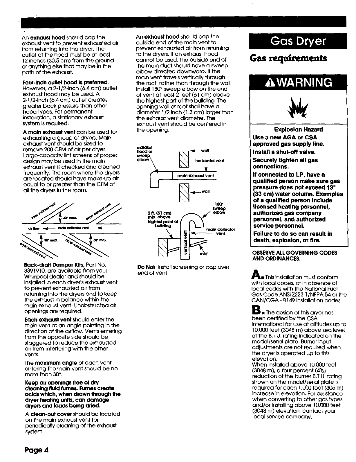
An exhaust hood should cap the
outside end of the main vent to
prevent exhausted air from returning
to the dryers. If an exhaust hood
cannot be used, the outside end of
the main duct should have a sweep
elbow directed downward. If the
main vent travels vertically through
the roof, rather than through the wall,
install 180° sweep elbow on the end
of vent at least 2 feet (61 cm) above
the highest part of the building. The
opening wall or roof shall have a
diameter 1/2 inch (1.3 cm) larger than
the exhaust vent diameter. The
exhaust vent should be centered in
the opening,
exhaust
elbow_ hol_ntol vent
___ 1 moln exhoustvent
_ _E--wall
211.161cm) j_/ elbow
building maincollector
vent
Do Net installscreeningorcap over
end ofvent,
Gas requirements
Explosion Hazard
Use a new AGA or CSA
approved gas supply line.
Install a shut-off valve.
Securely tighten all gas
connections.
If connected to LP, have a
qualified person make sure gas
pressure does not exceed 13"
(33 era) water column. Examples
of a qualified person include
licensed heating personnel,
authorized gas company
personnel, and authorized
service personnel.
Failure to do so can result in
death, explosion, or fire.
OBSERVEALLGOVERNING CODES
AND ORDINANCES.
Ae This installation must conform
with local codes, or in absence of
local codes with the National Fuel
Gas Code ANSI Z223.1/NFPA 54 or the
CAN/CGA - B149 installation codes,
Be The design of this dryer has
been certified by the CSA
International for use at altitudes up to
10,000 feet (3048 m) above sea level
at the B.T,U. rating indicated on the
model/serial plate. Burner input
adjustments are not required when
the dryer is operated up to this
elevation.
When installed above 10,000 feet
(3048 m), a four percent (4%)
reduction of the burner B.T.U. rating
shown on the model/serial plate is
required for each 1,000 foot (305 m)
increase in elevation, For assistance
when converting to other gas types
and/or installing above 10,000 feet
(3048 m) elevation, contact your
localservicecompany,
Page 4

Ca Check that dryer is equipped
with the correct burner for the
particular type of gas used. Burner
information can be found on the
serial/rating plate In the door well of
the appliance. If this information does
not agree with the type of gas
available, see your dealer,
D mThis dryer is equipped for use
with NATURAL GAS. It is certified by
CSA International for manufactured,
mixed and L.P, (propane and
butane) gases with appropriate
conversion. No attempt shall be
made to convert the appliance from
the gas specified on the serial/rating
plate for use with a different gas
without consulting the serving gas
supplier. Conversion must be done by
a qualified service technician. Gas
conversion kit port numbers are listed
on the gas valve burner base.
E mProvide a rigid gas supply line of
1/2-inch IPSpipe to the dryer
location. If the total length of the
supply line is more than 20 feet
(6.1 m), larger pLpe will be needed.
For L.P. gas usage, 3/8-Inch,
approved copper tubing may be
used, Pipe-joint compounds suitable
for use with L.P. gas should be use
FnThe supply line shall be equipped
with a shutoff valve installed within 6
ft. (1.8 m) of dryer in accordance with
the National Fuel Gas Code, ANSI
Z223,1 -- latest edition*. In Canada,
an individual manual shutoff valve
must be installed in accordance with
the B 149 installation codes CAN/CGA
B149.1 and CAN/CGA B149.2", This
valve should be located in the same
room as the dryer and should be in a
location that aUows ease of opening
and closing. Do Not block access to
the shutoff valve.
G i If the dryer is Installed in a
confined area such as a bathroom or
closet, provision must be made for
enough air for combustion and
ventilation. (Check governing codes
and ordinances, or refer to the
section of this instruction covering
recessed and closet installations.)
H m If local codes and ordinances
permit, it is recommended that new
flexible metal tubing, design-certified
by the AGA or CSA, be used for
connecting the dryer to the gas
supply line, (The gas feed pipe which
extends through the lower rear of the
dryer isprovided with 3/8-inch metal
pipe thread,)
el Lfrigid __
pipe is used
asa I I
combination of pipe fittings must
be used to obtain an in-line
connection to the dryer.
J n Make sure that lower edges of
the cabinet, plus the back and
bottom sides of the dryer are free of
obstructions to permit adequate
clearance of air openings for
combustion air, See "Recessed area
and closet installation instructions,"
page 12, for minimum spacing
requirements,
Ki For ease of installation,
operation and servicing (If ever
needed) adequate space should be
provided around the dryer,
Li A 1/8-inch NPT plugged tapping,
accessible for gauge testing, must be
installed immediately upstream of the
gas supply connection to the dryer,
The dryer must be disconnected from
the gas supply piping system during
any pressure testing of the system at
test pressures in excess of 1/2 psig.
The dryer must be isolated from the gas
supply piping system by closing the
equipment shut-off valve during any
pressure testing of the gas supply piping
system at test pressures equal to or less
than 1/2 psi (3,45 kPa)
EJectrlcal
requirements
Electrical Shock Hazard
Plug into agrounded3-prongoutlet.
Do not remove ground prong.
Do not useanadapter.
Do not use anextensioncord.
Failuretofollowthese instructlons
can result In death,tim, or electrlcal
shock.
A 120-volt, 60-Hz, AC-only, 15-or
20-ampere fused electrical supply is
required. A time-delay fuse or circuit
breaker is recommended,
It isrecommended that a separate
circuit serving only this appliance be
provided,
Ifcodes permit and a separate ground
wire isused, itisrecommended that a
qualified electrician determine that the
ground path Is adequate.
Recommended
ground method
The dryer, when installed, must be
electrically grounded in accordance
with local codes, or in the absence of
local codes, with the National
Electrical Code, ANSI/NFPA 70**, or
the Canadian Electrical Code, CSA
C22.1".
GROUNDING INSTRUCTIONS: This
appliance must be grounded. In the
event of malfunction or breakdown,
grounding will reduce the riskof
electric shock by providing a path of
least resistance for electric current.
The power supply cord plug must be
plugged into an appropriate outlet
that isproperly installed and
grounded in accordance with all
local codes and ordinances,
WARNING - Improper connection of
the equipment-grounding conductor
can result in a risk of electric shock.
Check with a qualified electrician or
serviceman if you are in doubt as to
whether the appliance isproperly
grounded. Do not modify the plug
provided with the appliance - if it will
not fit the outlet, have a proper outlet
installed by a qualified electrician.
3-prong ground-type
outlet
3-pron_ _
grouna _:_
.°°
power /
supply cord ground
Copies of the standards listed above may
be obtaLned from:
* CSA international
8501 East Pleasant Valley Road
Cleveland, Ohio 44131-5575
** National Fire Protection Association
One Batteryrnarch Park
Quinoey, Massachusetts 02269
prong
Important: Observe all gaveming
codes and ordinances. Page 5

Now Start...
With dryer in laundry area.
Excessive Weight Hazard
Usetwoor morepeople to moveend
installdryer.
Failureto do se can resultin beckor
otherinjury.
3-prong,
ground-type
gas supply line
mRemove the service door of the
meter case, Lift
the service door
up at the back
and remove,
install money-
accepting
device, (Refer to
manufaturer's
instructions for proper installation.)
For dryers using coin slides, use
adapter kit supplied with dryer.
Replace the meter case service door.
Put the coin vault with lock and key
the meter case opening,
• Move dryer close to final
position. Remove cardboard or
hardboard from under dryer.
• Remove red cap from gas pipe.
Carefully move dryer into final
position. Place level on top of the
dryer, first side to side; then front to
back, If the dryer is not level, adjust
the legs of the dryer up or down until
the dryer is level.
1. TO exhaust dryer, see Exhaust
requirements, Pages 3-4. Connect
exhaust vent system to dryer exhaust
outlet and exhaust hood using 4"
(10.2 cm) clamps, Use caulking to
seal exterior wall opening around
exhaust hood.
2. Carefully move dryer into
final position. Place level on top of
the dryer, first side to side; then front
to back. If the dryer is not level, adjust
the legs of the dryer up or down until
the dryer is level.
3 • Plug power supply cord Into
grounded outlet.
4 • Check dryer operation (some
accumulated time may be on the
timer due to factory testing).
Insert coins in slide and press slide in
slowly. (Operating time win
accumulate per number of coins and
1ype of timing cam used.) Push
START/RESTARTbutton. Using a full
heat cycle (not the air cycle), let the
dryer run for at least five minutes.
Dryer will stop when time is used up.
gas shutoff valve
l a Take tape off front corners of
dryer. Open dryer and remove the
literature and parts packages. Wipe
the interior of the drum thoroughly
with a damp cloth.
mTake two of the cardboard
corners from the carton and place
them on the floor in back of the dryer.
Firmlygrasp the body of the dryer
and genfiy lay it on its back on the
cardboard corners.
wWith one of the legs in hand,
check the ridges for a diamond
marking. That's how far the leg is
supposed to go into the hole.
i Start to screw the leveling legs
into the holes by hand. (Use a small
amount of liquid detergent to
lubricate the screw threads so it is
easier to turn the legs.) Use a 1-inch
wrench or socket wrench to finish
turning the legs until you reach the
diamond mark.
Now stand the dryer up,
Slide dryer onto cardboard or
hardboard before moving across floor
to avoid damaging floorcovering,
• Connect gas supply to dryer.
Use pipe-joint compound resistant to
the action of L.P, gas for gas
connections, if flexible metal tubing is
used, be certain there are no kinks,
If necessary for service, open the toe
panel, use a putty knife to press on
the toe panel lock located at the
center top of the toe panel Pull
downward on the toe panel to open.
Toe panel Is hinged at the bottom.
9m Open the shutoff valve in the
gas supply line.
lOre Usea non-corrosive leak
detection fluid to check for leaks.
Bubbles around connections will
indicate a leak, NEVER lEST FOR GAS
LEAKSWITH A FLAME. If a leak
appears, shut off gas valve controls
and adjust connections. Then check
connections again. Close toe panel
All connections must be wrench-
tightened.
Note: Dryer door must be closed for
dryer to operate. When door is open,
dryer stops, but fimer continues to run.
To restart dryer, close door and bush
START/RESTARTbutton.
5 • fffhe burner does notignite
and you can feel no heat inside 1he
dryer, shut off dryer for five minutes.
Check that all supply valve controls
are in "ON" position and that the
elecfrical cord is plugged in. Repeat
five-minute test,
6• If drying time is too long,
make sure lint screen is clean.
Page 6

Now Start...
Electrical
requirements
ifcodes permit and o separate
ground wire isused, It Is
recommended that a qualified
electdclan determine that the ground
path isadequate.
important: Observe all governing
codes and ordinances.
A four-wlreorthree-wire(Canada:
four-wireonly),sLngle-phase,120/240-
volt,60-Hz,AC-onlyelectrlcalsupply
(orfour-wlreorthree-wLre,120/208-
volt,ifspecifiedon themodel/serial
ratingplate)isrequiredon a
separate,30-ampere circuit,fusedon
bothsidesofthe line.A time-delay
fuseorcircuitbreakeris
recommended.
Recommended
ground method
In U.S.:
It isthe persenal responsibility and
obligation of the customer to contact
a qualified electrician to assure that
the electrical Installation isadequate
and in conformance with the
National Electrical Code, ANSI/NFPA
70", and all local codes and
ordinances.
In Canada.:
it isthe personal responsibility and
obligation of the customer to
install the dryer in accordance
with CAN I-B149 installation
codes** and all national or local
codes.
Canadian models are equipped
with a four-wire, 30-amp rated
flexible-type power cord. The
power cord must be plugged into
a mating 30-amp receptacle.
(NEMA type 14-30R).
Copies of the standards listed above may
be obtained from:
* National Fire Protection Association
One Balterymarch Park
Quincy, Massachusetts 02269
**CSA International
8501 East Pleasant Valley Road
Cleveland, Ohio 44131-5575
Excessive Weight Hazard
Usetwo or more peopleto moveand
install dryer,
Failureto do socanresult inback or
other injury.
With dryer in laundry area...
exhausr_'_
vent
l mTake tape off front corners of
dryer. Open dryer and remove the
literature and parts packages. Wipe
the interior of the drum thoroughly
with a damp cloth.
mTake two of the cardboard
corners from the carton and place
them on the floor in back of the dryer.
Firmly grasp the body of the dryer
and gently lay ff on its back on the
cardboard corners,
3_ With one of the legs in hand,
check the ridges for a diamond
marking. That's how far the leg is
supposed to go into the hole.
4m Start to screw the leveling legs
into the holes by hand, (Use a small
amount of liquid detergent to
lubricate the screw threads so it is
easier to turn the legs.) Usea 1-inch
wrench or socket wrench to finish
turning the legs unfil you reach the
diamond mark.
Now standthe dryerup.
Slide dryer onto cardboard or
hardboard before moving across floor
to avoid damaglng floor covedng.
box
5m Remove the service door of the
meter case, Uft
the service door
up at the back
and remove.
Install money-
accepting
device. (Refer to
manufaturer's
Instructions for proper Installation,)
For dryers using coin slides, use
adapter kit supplied with dryer.
Replace the meter case service door.
Putthe coin vault with lock and key
the meter case opening.
6m Move dryer close to final
position. Remove cardboard or
hardboard from under dryer.
Page 7

7 = U.S. installations:
Make electrical connection.
Thisdryer ismanufactured with the
cabinet-ground conductor
connected to the NEUTRAL(center) of
the wiring harness at the terminal
block. If local codes do NOTpermit
this type of connection, use "Four-
wire connection" Instructions.
For a grounded, cord-connected
appliance
GROUNDING INSTRUCTIONS:
Thisappliance must be grounded. In
the event of malfunction or
breakdown, grounding will reduce
the riskof electric shock by providing
a path of least resistance for electric
current,
If using a power suppiy cord, the plug
must be plugged into an appropriate
outlet that is properly installed and
grounded in accordance with all
local codes and ordinances.
WARNING - Improper connection of
the equipment-grounding conductor
can result in a risk of electric shock.
Check with a qualified electrician or
serviceman if you are in doubt as to
whether the appliance is properly
grounded. Do not modify the plug
provided with the appliance - if it will
not fit the outlet, have a proper outlet
installed by a qualified electrician,
Fora permanently connected
appliance --
GROUNDING INSTRUCTIONS:
This appliance must be connected to
a grounded metal permanent wiring
system; or an equipment-grounding
conductor must be run with the
circuit conductors and connected to
the equipment-grounding terminal or
lead on the appliance.
Canadian installations:
Fora grounded, cord-connected
appliance --
GROUNDING INSTRUCTIONS:
This appliance must be grounded. Ln
the event of malfunction or
breakdown, grounding will reduce
the risk of electric shock by providing
a path of least resistance for electric
current.
This appliance isequipped with a
cord having an equipment-grounding
conductor and a grounding plug. The
plug must be plugged Into an
appropriate outlet that Is properly
installed and grounded in
accordance with all local codes and
ordinances.
Page 8
WARNING - Improper connection of
the equipment-grounding conductor
can result in a riskof electric shock.
Check with a qualified electrician or
service representative or personnel if
you are in doubt as to whether the
appliance isproperly grounded. Do
not modify the plug provided with the
appliance - if ff will not fit the outlet,
have a proper outlet installed by a
qualified electrician.
Power supply cord
(o.s.o r)
Usea new UL-oppreved power supply
cord rated 240-volt mln., 30 amperes
and marked for use with a clothes
dryer.
-Fire Hazard
Use a new UL approved 30
ampere power supply cord.
Use a UL approved strain relief.
Disconnect power before making
electrical connections.
Connect neutral wire (white or
center wire) to center terminal
(silver).
Ground wire (green or bare wire)
must be connected to green
ground connector.
Connect remaining 2 supply
wires to remaining 2 terminals
(gold).
Securely tighten all electrical
connections.
i Failure to do so can result in
I death, fire, or electrical shock.
l)tmct wire (o.s.
Fire Hazard
Use 10 gauge solid copper wire.
Use a UL approved strain relief.
Disconnect power before making
electrical connections.
Connect neutral wire (white or
center wire) to center terminal
(silver).
Ground wlre (green or bare wire)
must be connected to green
ground connector.
Connect remaining 2 supply
wires to remaining 2 terminals
(gold).
Securely tighten all electrical
connections.
Failure to do so can result Jn
death, fire, or electrical shock.
I. Disconnect the power supply.
external ground
_ductor scmw
tab _ .... _'_ bald-
Y "n°' I/®*"
_ scrow
2. Remove hold-down screw
and terminal block cover,
strain _-d_/er
relief .F*'_ \cabinet
clamp _:_ _N-
3. Assemble relief
3/4"U,L.-listed screws
strain relief (U.L marking on strain relief]
into the hole below terminal block
opening. Tighten strain relief screws just
enough to hold the two clamp
sections together. Install power supply
cord/cable through the strain relief.
Complete installationfollowing
instructions for your type of
connection:
• Four-wire (recommended method)
• Three-wire (iffour-wire is not
available)

Four-wire connection...
Four-wire power supply cord must have
four, No.-10 copper wires and match a
four-wire receptacle of NEMA Type
14-30R. The fourth wire (ground
conductor) must be identified with a
green cover and the neutral
conductor by a white cover,
Four-wire receptacle (required for mobile home.,
4. Remove center terminal block
screw.
5. Remove appliance ground wire --
(green with yellow stripes) from
external ground connector screw.
Fasten under center, silver-colored
terminal block screw.
6. Connect ground wire (green) of
power supply cord to external
ground conductor screw. Tighten
screw.
7. Connect neutral wire (white or
center) of power supply cord under /'"1
center screw of the terminal block.
Tighten screw.
8. Connect the other wLresto outer _
terminal block screws. Tighten screws. _-_
9. Tighten strain relief screws. J/
10. Insert tab of terminal block cover
into slot of the dryer rear panel. Secure
cover with hold-down screw.
Strip 5" (12.7 cm) of outer
covering from end of t
cable. Leave Dare ground
wire at 5 inches (12.7 cm).
Cut 1-1/2" (3.8 cm] from
8 remaining wires. 8triD
insulation back " inch
(2.5 cm),
ShaDe
ends
of
wires
into c
nook
4,Remove center terminal block screw.
5. Remove appliance ground wire
(green with yellow stripes) from
external ground connector screw, t-"__
Fasten under center, silver-coLored
terminal block screw.
6. Connect the ground wire (bare)
of the power supply cable to the
external ground conductor screw,
Tighten screw,
7. Place the hooked end of the
neutral wire (white or center) of
power supply cable under the center
screw of terminal block (hook facing
right). Squeeze hook end together.
Tighten screw.
8. Place the hooked ends of the
other power supply cable wires
under the outer terminal block screws
(hook facing right), Squeeze hooked
ends together. Tighten screws,
9. Tighten strain reliefscrews.
I O. Insert tab of terminal block cover
into slot of dryer rear panel. Secure
cover with hold-down screw,
Page 9

Three-wire connection...
Three-wire power supply cord must have
three, No.-10 copper wires and match a
three-wire receptacle of NEMA Type
] 0-30R,
Three-wire receptacle
Where local codes permit
connecting cabinet-ground conductor to neutral wire:
4. Loosen or remove center
terminal block screw.
5. Connect the neutral wire (white,
or center) of power supply cord to
the center, sUver-colored terminal
screw of the terminal block.
Tighten screw,
6. Connect the other wires to
outer terminal block screws,
Tighten screws.
7, Tighten strain relief screws, _ _"_
8. Insert tab of terminal block _ \\ \\ _r
cover into slot of dryer rear panel - _,_\ -
Secure cover with hold-down_
screw.
Shape
Where local codes permit
connecting cabinet-ground conductor to neutral wire:
4, Loosen or remove center
terminal block screw,
5. Place the hooked end of the
neutral wire (white or center) of
power supply cable under the center
screw of the terminal block (hook
facing right), Squeeze hooked end
together, Tighten screw.
6. Place the hooked ends of the
other power supply cable wires
under the outer terminal block
screws (hook facing right). Squeeze
hooked ends together. Tighten f---%
screws,
7. Tighten strain relief screws..__'-'* _
18niolnS_trtt_br_ef _reram:npaalnb'e_.CskecC[°Veer _.
cover with hold-down screw.
| I
Page I0

Three-wire connection...
Three-wire power supply cord must
have three, No.-lO copper wires and
match a three-wire receptacle of NEMA
Type 10-30R.
Direct wire power supply cable must be
prepared as shown in "Preparing the
wire* of the three-wire connection
direct-wire steps above,
Three-wire receptacle
Where local codes Do Notpermit
connecting cabinet-ground conductor to neutral wire:
9. After reattaching the terminal
cover, connect a separate copper
4. Remove center terminal block
screw,
•_. Remove the appliance harness
ground wire (green with yellow
stripes) from the external ground
connector screw, Connect
appliance harness ground wire and
the neutral wire (white or center) of
the power supply cord/cable under
the center, silver-colored terminal
block screw. Tighten screw,
6. Connect the other wires to out_
terminal block screws, Tighten
screws.
ground wire from the external
ground connector screw to an
adequate ground•
¢o-'h
n To exhaust dryer, see Exhaust
requirements, Pages 3-4, Connect
exhaust vent to dryer exhaust outlet
and exhaust hood using 4" (10.2 cm)
clamps. Use caulking to seal exterior
wall opening around exhaust hood,
1 Carefully move dryer into final
position, Place level on top of the
dryer, first side to side; then front to
back. If the dryer isnot level, adjust
the legs of the dryer up or down until
the dryer is level•
1 On in U,S. or Canada, plug
power supply cord Into grounded
outlet. Or, in the U.S. only, connect
direct wire to power supply.
Turn power supply on,
7. Tighten strain relief screws. _ _
8. Insed tab of terminal block cover
into slot of dryer rear panel. Secure
cover with hold-down screw,
1 • Check dryer operation (some
accumulated time may be on the
timer due to factory testing).
Insert coins in slide and press slide in
slowly, (Operating time will
accumulate per number of coins and
Jype of timing cam used,) Push
START/RESTARTbutton, Using a full
heat cycle (not the air cycle), let the
dryer run for at least five minutes.
Dryer will stop when time isused up,
Note: Dryer door must be closed for
dryer to operate, When door Is open,
dryer stops, but timer continues to run,
To restart dryer, close door and push
START/RESTARTbutton.
o
2 • if drying time istoo long,
make sure lint screen isclean.
13. Now start the dryer and allow
it to complete a full heat cycle (not
air cycle) to make sure it is working
properly.
Page 11

Recessed area and
closet installation
instructions
This dryer may be installed in a
recessed area or closet. For recessed
area and closet installations,
minimum clearances can be found
on the serial tag on the dryer.
The installation spacing is in inches
and is minimum allowable, Addllional
spacing should be considered for
ease of installation, servicing and
compliance with local codes and
ordinances.
If closet door is installed, the minimum
unobstructed air openings in top and
bottom Is required, Louvered doors
with equivalent air openings are
acceptable,
Companion appliance spacing
should be considered,
The dryer must be exhausted
outdoors.
No otherfuei-buming appliance may
be Installed in the same closet,
Minimum Installation Clearances
(3&6 ore) :
I_lax.
ClOset
doer ---_
O"(ocm)*
[0 ¢m)"
_-- I. [2,,_cm )
15"
(38.1 cm)'*
0" (0 cm]"
ol °
Recessed Closet
front view side view
Maintenance
instructions
• Clean lint screen offer each cycle.
• Keep dryer area clear and free from
combustible materials, gasoline and
other flammable vapors and liquids.
• Do not obstruct the flow of
combustion and ventilation air.
Moving the dryer
to a new location...
Slidedryer onto cardboard or
hardboard before moving across floor
to avoid damaging floor covering.
Gas dryer models:
• Disconnect electrical cord. Tape
securely to dryer.
• Shut off the gas supply valves in the
gas supply line.
• Disconnect gas pipe and fittings
from dryer and cap gas supply line.
Tape end of dryer gas pipe.
Elechic dryer models:
• Shut of electrical supply to dryer.
• Disconnect the power supply cord
or cable from the dryer terminal
block.
All models:
• Make sure leveling Legsare secure
in dryer base.
• Tape drum to front panel.
• Tape dryer door, lint screen and
end of gas pipe.
Before the appliance isremoved from
service or discorded, remove the
door to the dryer compartment.
If dryer does not
operate properly...
Check the following to be surethat:
I.Electric supply isconnected.
2. Circuff breakers are not tripped or
house fusesblown,
3. Door isclosed.
4, Controls are set in a running or
"ON" position,
5. Start button has been pushed
firmly.
6. For gas dryers, check that gas
supply shutoff valves are set in
open position.
If you need
assistance...
The Whirlpool Consumer Interaction
Center will answer any questions
about operating or maintaining your
dryer not covered in the Installation
Instructions. The Whirlpool Consumer
Interaction Center is open 24 hours
a day, 7 days a week. Just dial
1-800 NO BELTS(1-800-662-3587) --
the call is free.
When you call, you wi, need the dryer
model number and serial number.
Both numbers can be found on the
seflal-rating plate located on your
appliance,
3_ (7.6 cn_
0
I
Closet
front view
• Additional clearances fat wan, doo_ and floor
em_xh_elbo_w_beu_l u'r_l °r If exfoma'
** Openi .n_isminimum for clo6et door. Louvemd
door wli_ equivalent air opening is
acceptable.
Page 12

Product dimensions
__-_--t 29" (73.7 cm)-_
I"........... 7
I
i
ELECTRIC_ .......
4-3/4" 13" 4_(I 0.2 cm) (69.2 cm)
(12,1 cm) dla. 1-I/4" ]
29" (73.7 cm) dryer
(40,6 cm)
27-114"
3S"
(88.9 cm)
<--25- I12" (64.8 cm) -_
/ ....
/
f
I
I
non-coin-operated
models:
7-I/8" (18.1 cm)
coin-operated
models:
7-7/8" (20 cm)
I-I/4"--),-
(3.2 cm)
EXHA_',--W-4,--_.A--$........t
18-3/8" _,
146.7cm)
BACK VIEW
27" (68.6 cm) dryer
"q_-_-27" (68.6 cm)---_"
_mB I
(35.6 cm) |
13 I'
_33 cm_ 4" (10.2 cm)
__ i/ (,2.1cm>
_.-._; .... __
dlo. 4-314"
BACK VIEW
37"
(94 cm)
35"
(88.9 cm)
-r--
1"
12.5 era)
'r
I"
(2.5 cm)
-<--25-112" (64.8 cm) --_
4),/" m_b_
10-114"
LEFTOR
RIGHTSIDE ! .
ExHA0sT_
JN A _L,"
T
4-1/4"
(10.8 cm)
SIDEVIEW
SIDE VIEW
non-coin-
operated models:
7-118" (18.1 cm)
coin-operated
models:
7-7/8" (20 cm)
7-114"
(I 8,4 cm)
(35.9cm)
BOTTOM EXHAUST
PartNo.8316.558Rev.A
© 2000Whlripaol Corporation
Preparedby WhlrlpoolCorporation,Benton Harbor,Michigan49022
PrintedinU,S,A.
 Loading...