

Page 1

WHIRLPOOL CONSUMER SERVICES
October 2001
Model AWM6100
WHIRLPOOL AUSTRALASIA
CONSUMER SERVICES
SERVICE MANUAL
FRONT LOAD
WASHING MACHINE
Model AWM6100
Version 8570 610 53000
Copyright © 2001 Whirlpool (Australia) Pty. Limited
All rights strictly reserved. Reproduction or issue to third parties in any form whatsoever is
not permitted without written authority of Whirlpool (Australia) Pty. Limited
Whirlpool is a registered trademark of Whirlpool U.S.A.
This documentation is intended only for qualified technicians who possess the required qualifications and
are aware of the regulatory requirements applicable to servicing electrical appliances.
Whirlpool (Australia) Pty Limited Part No. SM3022
A. B. N. 28 003 578 023
Page 2

WHIRLPOOL CONSUMER SERVICES
BLANK PAGE
Model AWM6100
Page 2 of 22
Page 3

WHIRLPOOL CONSUMER SERVICES
CONTENTS
TECHNICAL DATA 4 - 5
EXPLODED VIEW - CABINET 6
EXPLODED VIEW - DRUM 7
Model AWM6100
Page 3 of 22
Page
SPARE PARTS LIST 8 - 10
WIRING DIAGRAM 11
CIRCUIT DIAGRAM 12
PROGRAM DIAGRAM - Cotton 13
PROGRAM DIAGRAM - Synthetic 14
PROGRAM DIAGRAM - Delicate 15
PROGRAM DIAGRAM - Wool and Silk 16
PROGRAM DIAGRAM - Spinning Profiles 17
FAULT DIAGNOSIS 18
TEST SEQUENCE 19
FAILURE DURING NORMAL OPERATION 20
FAULT CODES 20
ADJUSTING DISTRIBUTION NOZZLE 21
TIMER CONNECTIONS 22
Page 4

WHIRLPOOL CONSUMER SERVICES
Model AWM6100
TECHNICAL DATA
Door lock
Dimensions
Height 845 mm
Width 595 mm
Depth 620 mm
Weight
Nett 73 kg
Mains Connection
Voltage 230 - 240 V
Frequency 50 Hz
Power consumption 2.3 kW
Lock time (20 °C) 3 - 6 s
Unlock time 60 - 90 s
Voltage 230 - 240 V
Rated current:
Contact 4 - 5 16 (4) A
Heating element
Heating Tubular heating element with
NTC - sensor
Rated Voltage 230 - 240 V
Rated power 2050 W
Resistance 22 - 28 Ω
Page 4 of 22
Drum
Volume 53 l
Capacity of dry laundry
Cotton/coloured 6 kg
Cotton rapid 3 kg
Cotton short 6 kg
Easy care 2.5 kg
Easy care rapid 1.5 kg
Easy care short 2.5 kg
Delicate 1.5 kg
Wool 1 kg
Water Level (as sensed by the pressure
switch)
Level 1
Switching point 60± 5 mmWc
Reset point 35± 5 mmWc
Overflow 280 ± 20 mmWc
Water (level visible inside the drum)
Level 1
Switching point 25 - 39 mm
Overflow 267 - 306 mm
Nominal currents
Contacts
11 - 12 4 (4) A
11 - 14 16 (4) A
11 - 16 1 (1) A
Resistance NTC :
0°C 35.9 κΩ
30°C 9.8 κΩ
40°C 6.6 κΩ
50°C 4.6 κΩ
60°C 3.2 κΩ
70°C 2.3 κΩ
95°C 1.1 κΩ
Inlet valve - Cold/hot fill :
Water temp (max) 60 °C
Rated flow <100 kPa 4 l/min
Pressure range 50 - 1000 kPa
Nominal voltage 220 - 240 V
Frequency 50 Hz
Minimum starting voltage:
< 600 kPa 160 V
600 - 1000 kPa 170 V
Nominal current 35 mA
Nominal input 6 VA
Nominal (20 °C) 3.4 - 4.5 kΩ
Drain pump (synchronous)
Nominal Voltage 230 - 240 V
Nominal current 0,3 A
Nominal power 34 W
Frequency 50 Hz
Resistor (coil) 155 ± 7% Ω
Motor protection 170 °C
Capacity(H=1,25m) 14 ± 2 l/min
Page 5

WHIRLPOOL CONSUMER SERVICES
Model AWM6100
TECHNICAL DATA (Cont.)
Program timer
Type SC1
Timer basic 4619 712 52201
Timer programmed 4619 744 80302
Nominal voltage 230 - .240 V
Frequency 50 Hz
Harness Connectors (See circuit
diagram)
OA4.1 - OA4.2 5. Option
OA4.3 - OA4.4 6. Option
OB4.1 - OB4.2 3. Option
OB4.3 - OB4.4 4. Option
OC4.1 - OC4.2 1. Option
OC4.3 - OC4.4 2. Option
SLT3.1 - SLT3.3 Temp.selector
SLS4.1 - SLS4.4 Spin speed selector
VCF3.1 - VCF3.3 Valve (cold water)
VHF3.1 - VHF3.3 Valve (hot water)
Pi5.1 = negative supply
Pi5.2 = data
Pi5.3 = clock
Pi5.4 = positive supply
Pi 5.5 = negative supply
PL3.1 - PL3.3 Pilot lamp
Connector
M7.1 - M7.7 Motor
DP2.1 - DP2.2 Pump
SET2.1 - SET2.2 NTC
DSS3.1 - DSS3.3 Door switch
PR2.1 - PR2.2 Pressostat
Speeds
Wash speed 54 rpm
Ramp speed 95 rpm
Spin speed 1200 rpm
Ambient Temperatures
Ambient temperature up to 70 °C
Storage temperature up to 85 °C
Output
Motor M7.6 - DSS 3.2 >40 V
in pump step AQ2.1 -DSS 3.2 240 V
NTC not measurable
Pump DP2.1 -DP2.2 240 V
Doorlock DSS3.1 -DSS 3.3 240 V
Pressostat E4 - E2 240 V
- empty PR2.1 - E2 240 V
- full PR2.2 - E2 240 V
Valve (Rast 2,5) V2.1 - V2.2 >170 V
Options not measurable
Display module Pi5.1 - Pi5. 5 V
Pi5.4 - Pi5.5 12 V
Motor
Type MCA52/64 - 148 t.f.
WHE 0
Belt ratio i = 1 : 15.9
Resistance contacts
6 - 7 68.7± 7% Ω
4 - 5 2.15± 7% Ω
2 - 3 1.89± 7% Ω
1 - 3 0.84± 7% Ω
Page 5 of 22
Single connector
HE2.1 - HE2.2 Heating element
PS2.1 - PS2.2 Pressostat
SM3.2 - SM3.3 Mains switch (3 fold
connector)
Program 32 positions
Step Cotton
/
Colour
Pre
wash
Main
wash
Rinse 22-28 22-28 22-28 22-28 22-28
Spin 29-31 29-31 29-31 29-31 29-31
Stop 32 32 32 32 32
02-06 03-06 04-06 - -
07-21 12-21 14-21 17-21 18-21
Easy
care
Delicate
Wool Silk
Page 6
WHIRLPOOL CONSUMER SERVICES
Model AWM6100
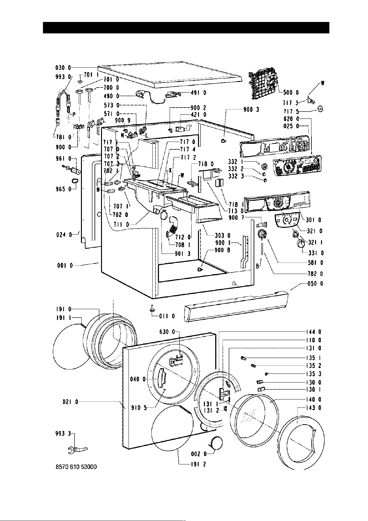
EXPLODED VIEW - CABINET
Page 6 of 22
Page 7
WHIRLPOOL CONSUMER SERVICES
Model AWM6100
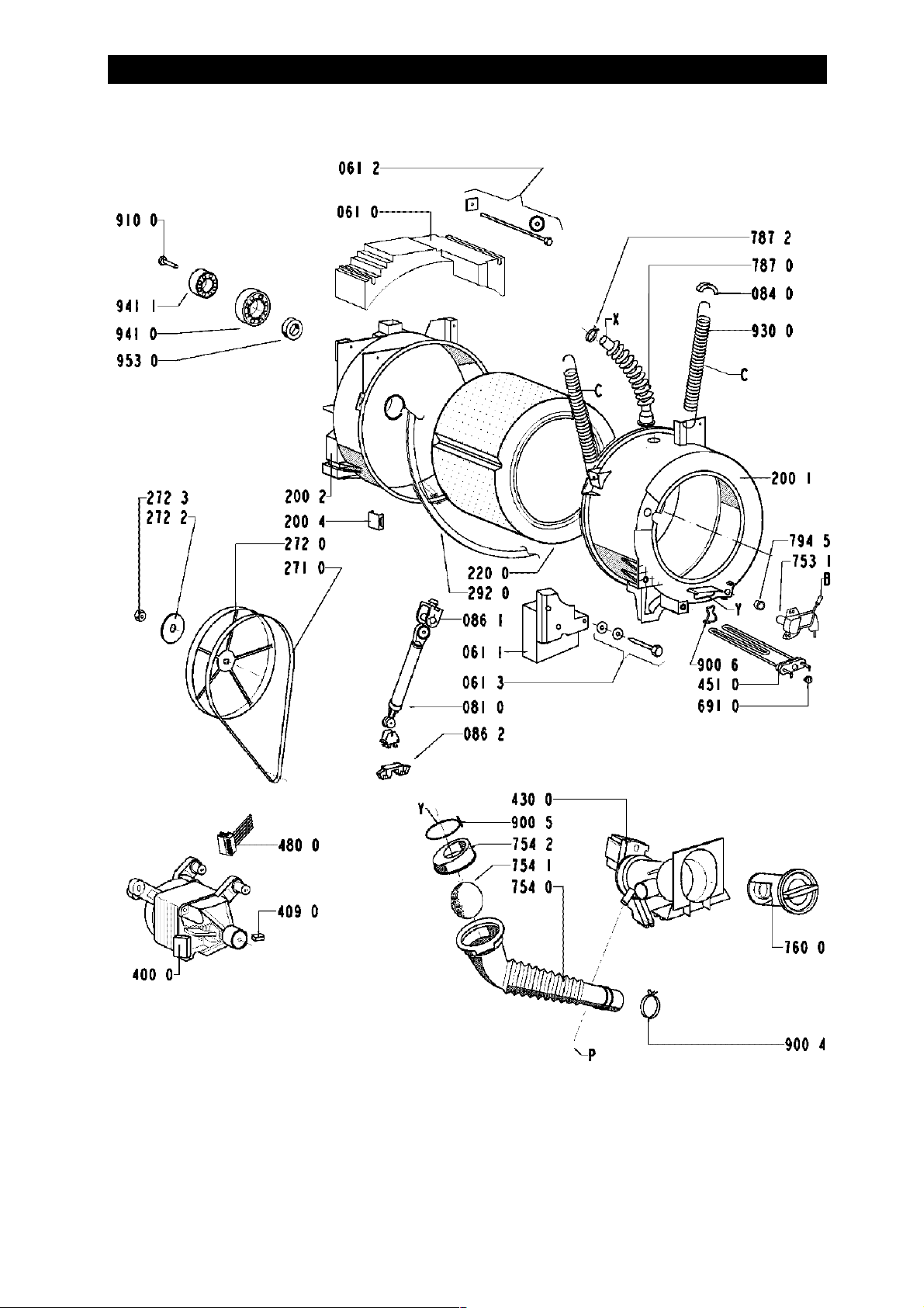
EXPLODED VIEW - DRUM
Page 7 of 22
8570 610 53000
Page 8

WHIRLPOOL CONSUMER SERVICES
Model AWM6100
PARTS LIST
Item Part No Description
001 0 4819 440 19716 Cabinet
002 0 4812 440 19343 Flap
011 0 4819 462 48472 Foot
021 0 4812 440 19818 Front
024 0 4812 440 18998 Panel, rear
025 0 4812 404 38551 Support control board VBL WH
030 0 4812 310 18586 Table top VBL WH
040 0 4812 417 18787 Hinge
050 0 4812 440 10406 Pedestal VBL, 53 l
061 0 4812 466 88458 Counter weight upper
061 1 4812 466 88459 Counter weight front
061 2 4819 310 39227 Mounting kit Weight top
061 3 4819 310 39228 Mounting kit Weight bottom
081 0 4812 529 18038 Shock absorber until 1200
084 0 4812 466 58001 Anti rattle, support spring
086 2 4812 401 18412 Stopper
110 0 4812 498 18139 Handle, door white
130 0 4812 417 28047 Plate Door lock
130 1 4812 417 28048 Plate, Doorlock, Lower
131 0 4812 417 28046 Lock Door
131 1 4812 417 28045 Pin Door Lock
131 2 4812 492 58022 Spring Door Lock
135 1 4812 498 18137 Knob Door safety
135 2 4812 491 48004 Spring
135 3 4812 290 68153 Holder, adjust. Door safety switch
140 0 4812 450 68219 Door glass
143 0 4812 440 19782 Glass door frame VBL WH
144 0 4812 440 19589 Frame, door glass DE-WT
191 0 4812 460 68527 Door bellow standard
191 0 4812 460 68532 Door bellow WH grease resistance
191 1 4812 492 18017 Strap
191 2 4819 530 58059 Ring
200 1 4812 418 18283 Tub 53l front
200 2 4812 418 18318 Tub rear
200 4 4812 290 88054 Clamp for tub WH
220 0 4812 418 18281 Drum 53l, 1000
271 0 4812 358 18056 V-ribbed belt WH 1250 J5
272 0 4812 528 58027 Pulley DIAM. 298
272 2 4812 532 18024 Washer
272 3 4812 505 18371 Nut M 12
292 0 4812 530 58101 Gasket Tub
301 0 4812 452 10744 Control panel
303 0 4812 498 78114 Handle
321 0 4812 452 10745 Insert panel
321 1 4812 532 98011 Fastener, Inlay
Page 8 of 22
Page 9

WHIRLPOOL CONSUMER SERVICES
Model AWM6100
PARTS LIST (Cont.)
Item Part No Description
331 0 4812 414 58111 Knob, timer VBL complete
332 1 4812 513 18097 Push button, start VBL WH
332 2 4812 513 18098 Push button, spin speed VBL WH
332 3 4812 513 18099 Push button option VBL WH
400 0 4812 361 18301 Motor 800/1000 MCA 52
409 0 4812 362 48004 Brush, carbon motor CESET
421 0 4812 121 18142
430 0 4812 310 38525 Pump, drain with thermal protection
451 0 4812 259 28766 Heating element 240V, 53l
490 0 4812 310 18404 Kit cable, mains 5m 3x1,5
491 0 4812 321 28367 Strain relief
500 0 4812 282 18788 Timer SC1 (EI,PW,IR,RH)
571 0 4812 281 28382 Valve, magnet cold
573 0 4812 271 28449 Valve, magnet hot
581 0 4812 271 28441 Pressostat
620 0 4812 452 10374 Module Timer B S/DS
630 0 4812 280 58026 Door lock 3 TABS
691 0 4812 282 18702 Sensor NTC (SC1)
700 0 4812 530 28869 Hose, inlet hot
701 0 4819 530 28848 Hose, inlet
701 1 4819 466 69704 Gasket and filter
702 0 4819 530 29019 Hose internal
702 1 4819 530 28971 Hose, inlet internal
707 0 4812 526 48031 Nozzle Distribution
707 1 4812 526 48028 Nozzle
707 2 4812 526 48029 Nozzle
707 3 4812 526 48035 Nozzle hot
708 1 4812 530 48143 Bend
711 0 4812 418 88054 Detergent disp. 3C, 53l
712 0 4812 418 68198 Drawer 3 Compartment VBL
713 0 4812 418 88019 Flap Detergent Container
717 0 4812 418 78925 Bowden cable
717 1 4812 321 38013 Lever, Nozzle
717 2 4812 321 38012 Holder, adjustable
717 3 4812 278 88017 Slide
717 4 4812 492 38359 Spring, Nozzle
717 5 4812 282 18807 Cam for 3 Compartment drawer, SC1/VBL/WH
718 0 4812 526 48051 Siphon
718 1 4812 418 88018 Accessory
753 1 4819 418 68234 Chamber, air
754 0 4812 530 28826 Drain hose
754 1 4812 530 28832 Lock eco
754 2 4812 530 28829 Flange eco
760 0 4812 480 58105 Filter set pump
781 0 4819 530 28847 Drain hose
Interference filter 1,00 µF
Page 9 of 22
Page 10

WHIRLPOOL CONSUMER SERVICES
Model AWM6100
PARTS LIST (Cont.)
Item Part No Description
782 0 4812 530 28827 Hose, pressostat
787 0 4812 530 28813 Steam hose
787 2 4819 401 18868 Clamp, hose 26,8 mm
794 5 4812 530 58095 Gasket, air trap
900 0 4812 255 18204 Holder, hose outlet
900 1 4812 290 88049 Bracket
900 2 4812 290 88077 Cable, clamp
900 3 4812 401 18446 Cable, clamp
900 4 4819 401 18872 Clamp, hose
900 5 4819 401 18529 Clamp, hose
900 6 4812 401 18444 Support, heating element
900 7 4812 256 98031 Holder, pressostat
900 8 4819 401 18823 Clamp
900 9 4819 404 78449 Support
901 3 4812 401 18414 Clamp, hose
910 0 4812 502 18383 Screw, Torx T40 M 8X 25
910 5 4812 502 18516 Screw 4,2 x 13
930 0 4819 492 38139 Spring, Suspension
941 0 4812 520 28004 Bearing, ball 6206
941 1 4812 520 28066 Bearing, ball 6204
953 0 4812 530 58099 Shaft seal 1200
961 0 4819 532 68829 Spacer
965 0 4812 466 68545 Cover BK/WH
993 0 4819 530 29028 Bow
993 3 4812 395 58004 Tool
Page 10 of 22
Page 11

WHIRLPOOL CONSUMER SERVICES
Model AWM6100
WIRING DIAGRAM
00 Black
11 Brown
22 Red
33 Orange
44 yellow
55 Green
66 Blue
77 Violet
88 Grey
99 White
45 Yellow/Green
Page 11 of 22
Page 12

WHIRLPOOL CONSUMER SERVICES
Model AWM6100
CIRCUIT DIAGRAM
Page 12 of 22
Page 13

WHIRLPOOL CONSUMER SERVICES
Model AWM6100
PROGRAM DIAGRAM - Cotton
Page 13 of 22
Page 14

WHIRLPOOL CONSUMER SERVICES
Model AWM6100
PROGRAM DIAGRAM - Synthetic
Page 14 of 22
Page 15

WHIRLPOOL CONSUMER SERVICES
Model AWM6100
PROGRAM DIAGRAM - Delicate
Page 15 of 22
Page 16

WHIRLPOOL CONSUMER SERVICES
Model AWM6100
PROGRAM DIAGRAM - Wool and Silk
Page 16 of 22
Page 17

WHIRLPOOL CONSUMER SERVICES
Model AWM6100
PROGRAM DIAGRAM - Spinning Profiles
Page 17 of 22
Page 18

WHIRLPOOL CONSUMER SERVICES
Model AWM6100
Page 18 of 22
FAULT DIAGNOSIS
1. The diagnostic tests must be performed on the machine without a wash load because the
out of balance detection system is disabled.
2. Set the cycle selector to "DRAIN"
3. Press :
a) "RINSE HOLD" button twice
b) "INTENSIVE RINSE" button twice
c) "START" button once,
4. The control panel will now display :
• 1000 speed LED on (Does not change for duration of the test sequence).
• "PREWASH" programme sequence LED on
• "WASH" programme sequence LED on
• "RINSE" programme sequence LED on
• "RINSE HOLD" programme sequence LED on
• "DRAIN/SPIN" programme sequence LED on - (This is Step 1 in the Table over)
5. Drain pump runs for approximately six seconds and the test sequence automatically
advances to Step 2.
6. By pressing the Prewash button once, the timer advances to step 3
Page 19

WHIRLPOOL CONSUMER SERVICES
Model AWM6100
TEST SEQUENCE
Page 19 of 22
Pump Out
by pressing :
(See Note 1)
1 Start Pump out - - Stationary Rinse hold and
2 Advances
automatically
3 Prewash button Main
4 Easy iron button Main
5 Auto (or press
rinse hold button)
(Note 2)
6 Rinse hold button Fill via
Rinse hold button
7
Advances
8
automatically
(Note 3)
or Fill Via
:
Prewash Cold fill, no
wash
wash
Main
wash
fabric
softener
Pump out - 10s on,
Pump out - 6 min Spin Max
Temperature Time Drum
60 s (fill) Stationary Prewash button
heat
Warm fill, no
heat
Warm fill,
heat to 90°C
Cold fill, no
heat
Cold fill, no
heat
60 s (fill) Stationary Main wash fill
60 s (fill)
25 min
heat
55 s (fill) 80 s on,
60 s 80s on,
Rhythm
10 s on,
6 s off
2 s off
2s off
6s off
speed
Component(s)
Checked
Intensive rinse
buttons
and prewash fill
Heating circuit,
NTC, leakage
Easy ironing
button
Fabric softener fill
Pump
Pump, spin
LED *Step Advance to step
PWRRHD
*Programme Sequence LED's: P = Prewash W = W ash R = Rinse RH = Rinse Hold D = Drain
Note 1 Unless indicated by "Advances automatically", the test cycle can only be advanced by
pressing the appropriate button once within five minutes, otherwise the machine will
pump out and a false fault will be indicated.
Note 2. This part of the test sequence can be terminated after the fill by pressing the "Rinse
hold" button but the NTC will not be checked for accuracy.
Note 3. This part of the test sequence can be terminated at any time by changing the cycle on
the cycle selector then reselecting drain and press the start button. Once the machine
is empty of water, the start button may be pressed and held until the start button light
goes off to reset the timer ready for the next wash.
If a failure is detected during the test sequence the timer will :
1. Initiate the safety step routine :
A. Drain pump runs until pressure switch resets plus 30 seconds.
I. Main motor is turned off.
II. Water inlet valves are turned off.
III. Element is turned off
2. Stop the machine and illuminate the speed indicator LED's in a pattern to indicate the
fault code.
Page 20

WHIRLPOOL CONSUMER SERVICES
Model AWM6100
Page 20 of 22
FAILURE DURING NORMAL OPERATION
If a failure is detected during normal operation, the machine will stop, the programme sequence
LED where the failure occurred will flash and the speed indicator LED's will illuminate in a
pattern to indicate the fault code.
FAULT CODES
Failure135679111416182021
Speed
LED's
Fault Detected Malfunction Perform the following:
1 Water not entering or not detected Check tap, cold inlet valve, pressure switch
3 Drain failure or not detecting
empty drum
5 NTC failure Check NTC
6 Tachometer failure (no motor
movement detected
7 Circuit board failure (motor triac) Replace timer
9 Drain failure Check drain pump, pressure switch, blocked
11 Electronic failure Replace timer
14 Electronic failure Replace timer
16 Control failure Replace timer
18 Control failure Replace timer
20 Control failure Replace timer
21 Control failure Replace timer
Check pressure switch, blocked drain, drain
pump
Check motor
drain
Page 21

WHIRLPOOL CONSUMER SERVICES
Model AWM6100
Page 21 of 22
ADJUSTING DISTRIBUTION NOZZLE
1. Select any COTTON wash cycle with the prewash off and wait until water begins to enter
machine.
2. Turn the machine off at the power point.
3. Remove the machine lid.
4. Adjust the lever until the red pointer is over the index mark.
5. Replace the machine lid, turn on the power, open the detergent drawer slightly and make
sure that water is only entering the main wash (middle) compartment and that no water is
entering the fabric softener compartment.
Index
Mark
Adjustment
Lever
Page 22

WHIRLPOOL CONSUMER SERVICES
Model AWM6100
TIMER CONNECTIONS
Page 22 of 22
 Loading...