

Whirlpool AWM 240, AWM 243, AWM 245 INSTRUCTION FOR USE
INSTALLATION INSTRUCTIONS
MOBILITY WHEELS
(for UK only)
Depending on model, your washing machine is
provided with mobility wheels.
You will find these wheels in the accessory kit supplied
with the machine, or you can order them from our
After-Sales Service.
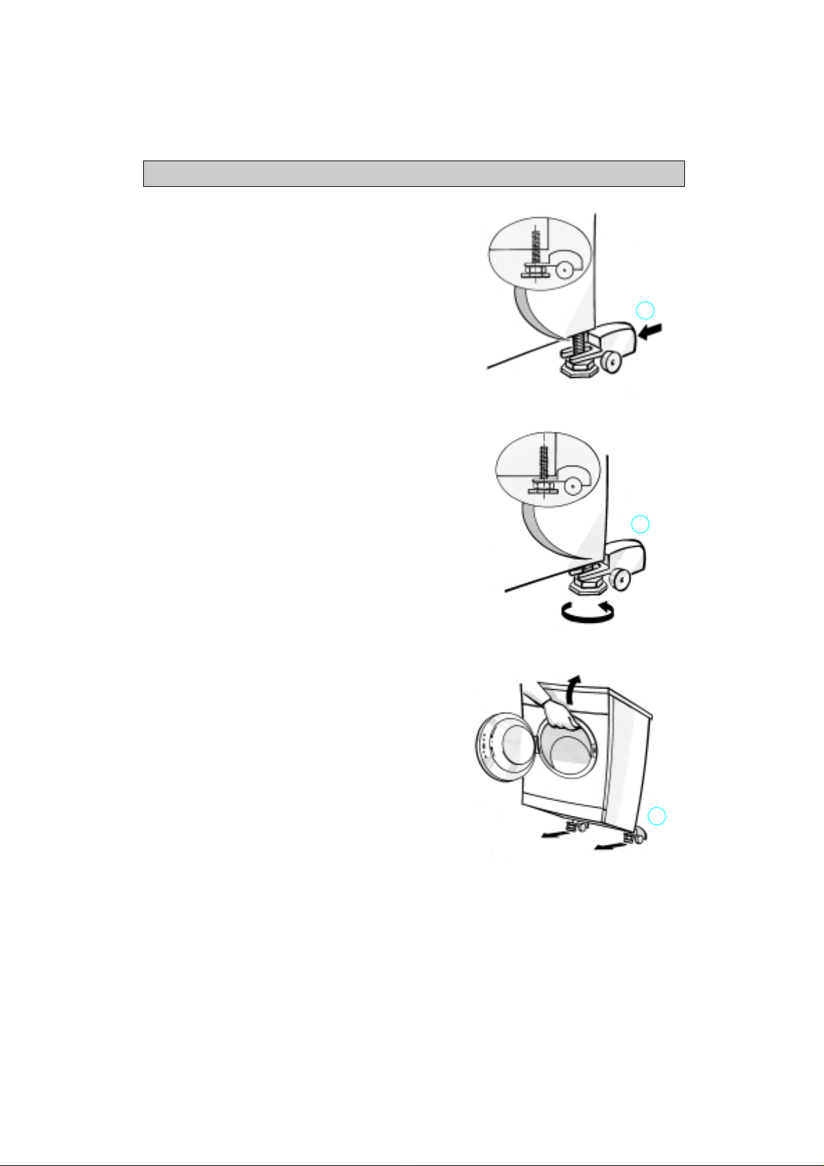
MOUNTING INSTRUCTIONS
1.
Tilt the machine forward.
2.
Loosen the two rear feet.
3.
Insert the wheels as close as possible to the
screw (1).
4.
Tighten the screw completely (2).
5.
Put the machine in an upright position.
6.
Adjust the front feet making sure that the machine
is completely level with the floor.
Note
: Levelling is extremely important to avoid any
risk of instability and vibrations.
1
2
MOVING THE MACHINE
1.
Open the door of the machine.
2.
Lift the machine by 1 or 2 cm (3).
3.
Push or pull the machine according to your need.
3
19
INSTALLATION INSTRUCTIONS
1) ELECTRICAL CONNECTIONS
“Warning - this appliance must be earthed”
This appliance is normally supplied with a mains
lead having a plug fitted in the factory which has
been checked for correct earth continuity.
If the fitted plug is not suitable for your socket
outlet, or if the machine’s mains lead is not fitted
with a plug, you should fit a suitable new, good
quality plug by following the instructions in (2)
below.
Any unsuitable plug should be cut off and
disposed of in order to avoid a possible shock
hazard should it be inserted into a socket.
2) CONNECTION TO A REWIRABLE PLUG - to be
carried out only by a qualified electrician
The wires in the mains lead are coloured in
accordance with the following code:
BLUE - “NEUTRAL” (“N”)
BROWN - “LIVE” (“L”)
GREEN AND YELLOW - “EARTH” (“E”)
To fit a new plug, proceed as follows:
2.1Polarized Plugs (e.g. 3 pin, 13 amp plug
conforming to BS 1363A)
a.
The GREEN AND YELLOW wire must be
connected to the terminal in t he plug which is
marked with the letter “E” or by the Earth
symbol or coloured yellow or green and
yellow.
b.
The BLUE wire must be connected to the
terminal which is marked with the letter “N” or
coloured black.
c.
The BROWN wire must be connected to the
terminal which is marked with the letter “L” or
coloured red.
2.2Non-polarized plugs (e.g. 2 pin with side
earth contact)
The wire which is coloured GREEN AND
YELLOW must be connected to the earth
contact. The other two wires should be
connected to the two pins, irrespective of colour.
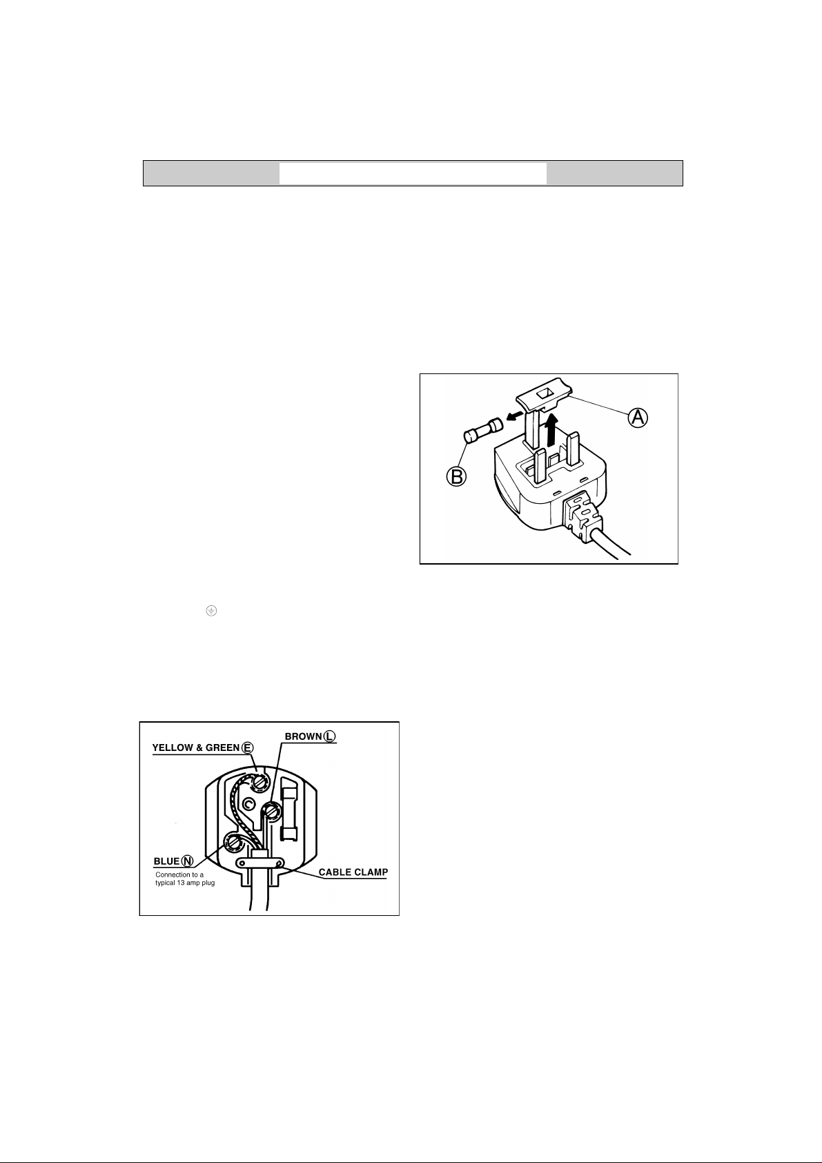
3) FUSE REPLACEMENT
If the mains lead of this appliance is fitted with a
BS 1363A 13 amp fused plug, replace the fuse
only with an A.S.T.A. approved type conforming
to BS 1362 and proceed as follows:
1.
Remove the fuse cover (A) and the fuse (B).
2.
Fit the replacement 13 A fuse into the fuse
cover.
3.
Refit both into the plug.
For all other types of plug, the supply socket
should be protected by a 16 A fuse or circuit
breaker at the distribution board.
18
INSTALLATION INSTRUCTIONS
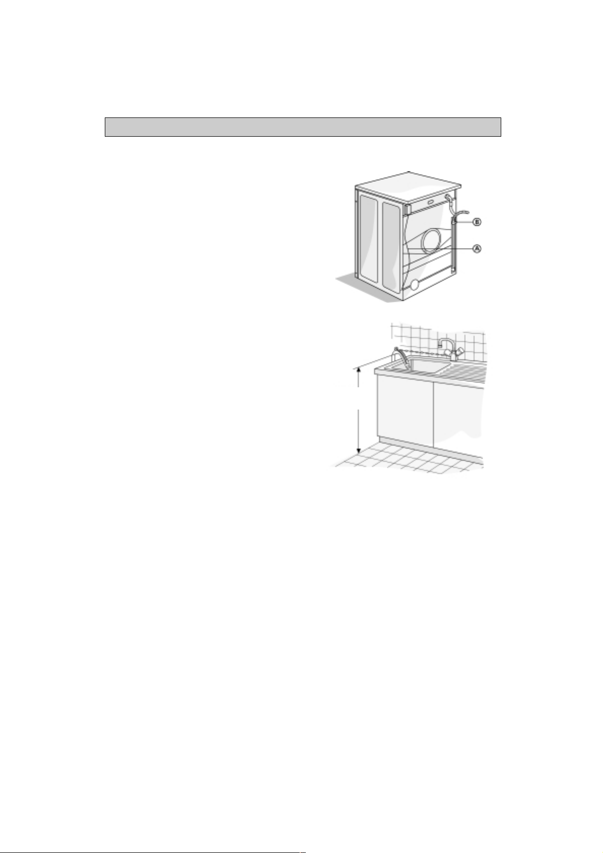
DRAIN HOSE
•
Drain hose connection to water outlet.
1.
Unhook the drain hose from the left clip;
see arrow A in Fig. 1.
Important:
Do NOT loosen the drain hose connection;
see arrow B in Fig. 1, otherwise there is the risk of
leakage (danger of scalding with hot water).
2.
Fit the drain hose either to the siphon or hook it
over the edge of a sink or bath tub with the “U”
bend (Fig. 1). Small hand basins are not suitable.
3.
Minimum drain height: 70cm.
Maximum U-bend drain height: 125 cm.
4.
If you need to add an extension, use a flexible
hose of the same type and secure the union with
screw-on hose clips. Maximum overall drai n ho se
length 2.5 m.
Important:
Make sure that there are no kinks in the drain hose run
and take precautions against it falling while the
appliance is running (Fig. 2).
Fig. 1
CONNECTION TO THE MAINS
•
Observe local utility company regulations.
•
The connection must be made with a correctly
installed, earthed and insulated socket.
•
The system must be earthed.
The manufacturer declines all responsibility for
injury to persons or pets and damage to property
caused by disregarding the above instructions.
•
The data concerning voltage, consumption and
necessary fuse are supplied on the inside of the
appliance door.
•
The mains connection cable may only be replaced
by a qualified electrician.
•
The appliance conforms to European safety
regulations, EC directive 93/68/EWG and
EN 60555.
•
Do not use extension leads or multiplugs.
Min 70 cm
Max 125 cm
Fig. 2
17

INSTALLATION INSTRUCTIONS
WATER SUPPLY
•
Water supply: only cold water.
•
Tap: 3/4” threaded hose connector.
•
Water pressure (mains pressure):
10-100 N/cm2 (1-10 bar).
For Great Britain and Ireland only
•
Water inlet: hot and cold fill. The warm water inlet
temperature must not exceed 60°C.
INLET HOSE(S)
Note:
If the inlet hose is already fitted to the rear panel
on the appliance, ignore points 1 and 4.
1.
Remove the inlet hose from the drum.
2.
Fit the mesh filter supplied in the thread between
the straight end of the inlet hose(s) and the tap(s).
3.
Carefully screw the straight end of the inlet hose(s)
to the tap(s) by hand.
4.
Screw the curved end of the hose to the appliance
taking care that the hose is not kinked.
5.
Turn the tap(s) on fully and check that the joints at
the washing machine and the tap(s) are watertight.
•
If the hose is not long enough, replace it with a
suitable length of pressure-resistant hose
(approved under EN 500 65 to withstand a
minimum of 10 bar).
•
Check the hose regularly for brittleness and cracks
and replace if necessary.
•
The washing machine may be connected without a
non-return valve.
•
Observe any special local regulations regarding
connection to the water supply.
16
INSTALLATION INSTRUCTIONS
INSTALLATION
•
Install the appliance on a solid and level floor
surface, preferably in a corner of the room.
•
Make sure that all four feet are resting firmly on
the floor and check that the appliance is perfectly
level (use a spirit level).
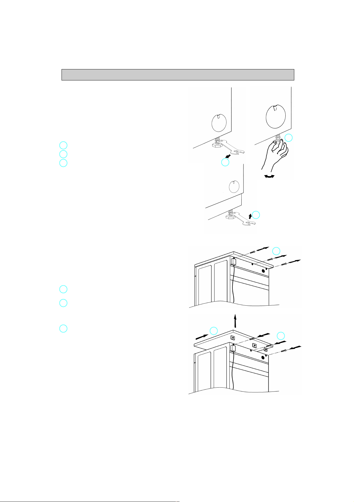
•
If the floor is uneven, adjust the levelling feet as
required (do not insert pieces of wood, cardboard
etc. under the feet).
Slacken the locknut using the spanner supplied.
1.
2.
Adjust the height of the foot, turning it by hand.
Tighten the locknut anticlockwise towards the
3.
washing machine.
•
If the appliance is to be inst alled on a wooden floor,
distribute the weight by placing it on a 60x60 cm
sheet of plywood at least 3 cm in thickness. Secure
the plywood sheet to the floor.
2
1
3
BUILD-UNDER / WORKTOP
The appliance must be installed only under a
fitted, continuous kitchen worktop.
The appliance must only be built under using the
built under set UBS.
•
Unplug the appliance from the mains.
1.
Unscrew the worktop fixing screws from the rear
of the appliance.
Slide the worktop fully backward and lift it
2.
upwards to remove.
Install the cover panel following the relative
instructions.
Refit the fixing screws and tighten them.
3.
BUILD-UNDER OPENING DIMENSIONS
Width 600 mm
Height 825 mm
Depth 600 mm
WARNING:
Only plug the machine into the mains power socket
after you have fitted the cover panel or the machine
worktop.
1
2
3
15

INSTALLATION INSTRUCTIONS
TRANSIT BOLTS
The appliance is fitted with transit bolts to prevent
internal damage while it is being moved.
Before using the appliance the transit bolts MUST
be removed (Fig. 1).
1.
Slacken the bolts with the spanner supplied (Fig. 2).
2.
Unscrew the bolts by hand.
3.
Hold each bolt head and pull the bolts complete
with red plastic spacer through the wide part of the
holes.
4.
Close the holes with the provided plastic caps.
Fit the caps in the direction indicated by the arrow
in the large opening and slide them into the narrow
slot until they sit properly (Fig. 3).
5.
Keep the transit bolts for future use.
Note:
Fit the transit bolts before transporting the appliance as
follows:
1.
Pry up the plastic caps with a screwdriver, slide
them out against the direction indicated with the
arrow and remove them.
2.
Fit the transit bolts by following the above
procedure in reverse order.
Fig. 1
Fig. 2
14
Fig. 3
 Loading...