

AKM 520-522 PRODUCT DESCRIPTION SHEET
IT
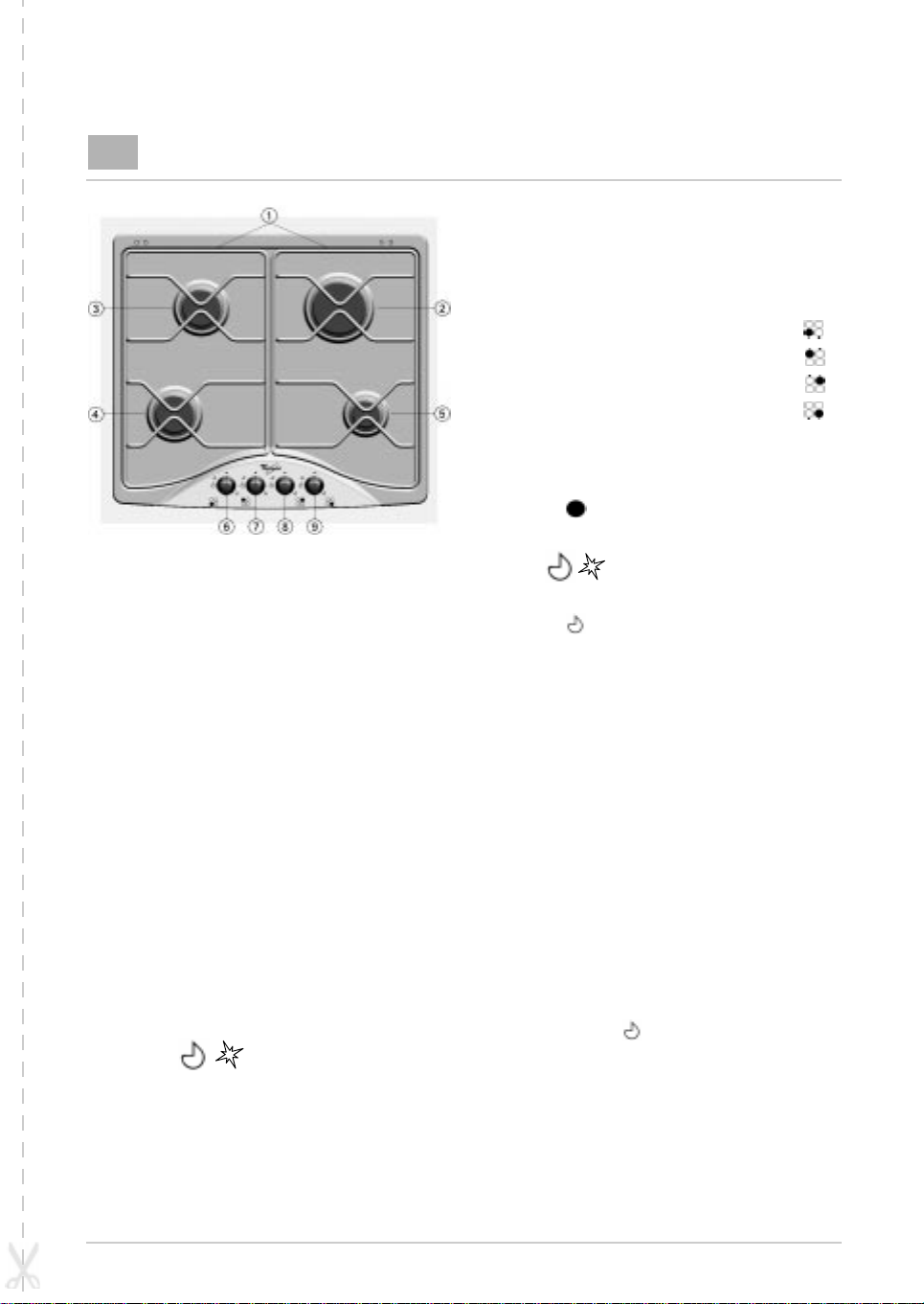
1. Removable panstand grids
2. Large burner
3-4. Medium burners
5. Small burner
6. Medium burner control knob
7. Medium burner control knob
8. Large burner control knob
9. Small burner control knob
Symbols
Operation of burners with safety
device and electric ignition
To light one of the burners:
• Press the relative knob and turn it anticlockwise to the large flame and star
setting .
• At the same time, keep the knob pressed
against the control panel until the burners
ignites.
• After the burner has ignited, keep the knob
pressed for about 10 seconds.
• Release the knob.
If the burner does not ignite, repeat the operations
described above.
5019 319 53051
Shaded
circle
Large
flame
Small
flame
Tap closed
Maximum opening/flame
delivery and electric and star
ignition
Minimum opening or reduced
delivery
Note:
— Should particular local conditions of the
delivered gas make the ignition of the burner
difficult, it is advisable to repeat the
operation with the knob turned to the small
flame setting .
— The safety device of the burner shuts off the
gas supply to the burner if its flame goes out
accidentally (because of a sudden gust of
wind, an interruption in the gas delivery, the
overflowing of liquids, etc.).
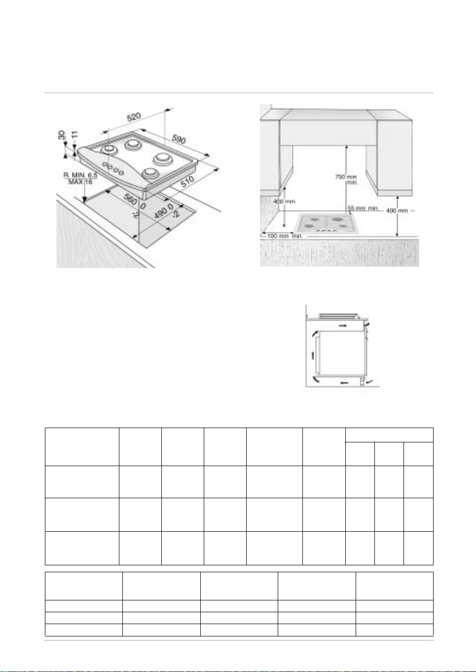
DIMENSIONS OF COOKING HOB AND WORKTOP
NOTE: In case of installation of a hood above the cooktop, please refer to the hood
instructions for the correct distance.
Important:
If the cooktop is installed over a built-in oven
without forced ventilation cooling, make sure there
are air inlets and outlets to allow adequate
aeration inside the cabinet. Figure A illustrates an
assembly example.
—
FIG. A
INJECTORS TABLE CATEGORY II2H3+
Type of gas used
NATURAL GAS
(Methane) G 20
LIQUID PETROLEUM
GAS
(Cylinder) G 30
LIQUID PETROLEUM
GAS
(Cylinder) G 31
Type of gas used
G 20 20 mbar 4 gas 7.30 695 l/h 14.6
G 25 28-30 mbar 4 gas 7.30 531 g/h 14.6
G 31 37 mbar 4 gas 7.30 521 g/h 14.6
Type of
burner
large
medium
small
large
medium
small
large
medium
small
Appliance
model
Injector
marking
128
94
76
85
65
50
85
65
50
Rated
heat
capacity
Pcs-kW
3.00
1.65
1.00
3.00
1.65
1.00
3.00
1.65
1.00
Total rated heat
capacity Pcs-kW
Rated
consumption
218 g/h
120 g/h
214 g/h
118 g/h
286 l/h
157 l/h
95 l/h
73 g/h
71 g/h
Reduced
heat
capacity
Pcs-kW
0.60
0.35
0.30
0.60
0.35
0.30
0.60
0.35
0.30
Total rated
consumption
Gas pressure
min. rat. max.
17 20 25
20 28-30 35
25 37 45
Air required
for burning m
3
/h
 Loading...