

Page 1

6gb61801b.fm5 Page 11 Friday, April 11, 2003 2:44 PM
INSTRUCTIONS FOR USE
BEFORE USING THE COOKTOP
SUGGESTIONS FOR ENVIRONMENT
PROTECTION
PRECAUTIONS AND GENERAL ADVICE
ENERGY SAVING TIPS
CARE AND MAINTENANCE
TROUBLESHOOTING GUIDE
AFTER SALES SERVICE
INSTALLATION
11
Page 2
6gb61801b.fm5 Page 12 Friday, April 11, 2003 2:44 PM
BEFORE USING THE COOKTOP
These instructions are only valid for those
Countries where the destination abbreviations are
mentioned on the rear cover of the user
instructions and on the appliance.
• To get full satisfaction of your cooktop,
please read these instructions carefully
and keep them for future consultation.
Keep the packaging material (plastic bags,
•
polystyrene parts, etc.) out of the reach of
children, as they are potentially dangerous.
Check whether the cooktop has been damaged
•
during transport.
• Ensure that the installation and gas/electrical
connections are performed by a qualified
technician, following the manufacturer's
instructions and in compliance with current
local safety regulations.
SUGGESTIONS FOR ENVIRONMENT
PROTECTION
1. Packaging
The packaging material is entirely recyclable, and is
marked with the recycling symbol , which
identifies it as a type of material that must be sent
to local waste-disposal centres.
2. Product
The cooktop is made out of recyclable material.
When scrapping it, comply with local wastedisposal regulations. Before disposing of it, cut its
power cable off in order to render it inoperative.
PRECAUTIONS AND GENERAL ADVICE
• Before any cleaning or maintenance
operation, disconnect the cooktop from
mains power supply.
• The use of a gas appliance produces heat
and humidity in the room. Ensure that the
room is well ventilated, or install an
extractor hood with exhaust duct.
• In case of prolonged use, additional ventilation
may be needed (opening a window or
increasing the extraction force of the hood).
• Keep children away from the cooktop when
it is in use.
• After use, ensure that the knobs are in
position (off), and close the main gas
delivery valve or the gas cylinder valve.
• Caution: the lid (where present) might
break if overheated. Before closing it, make
sure that all the burners are off.
• Warning: The protective rubber feet on the
panstand grids represent a choking hazard
for young children. After cleaning the
panstand grids, please ensure that all the
rubber feet are correctly fitted.
12
Declaration of conformity
• This cooktop has been designed,
constructed and marketed in compliance
with:
- safety requirements of EEC Directive
“Gas” 90/396;
- safety requirements of EEC Directive
“Low voltage” 73/23;
- protection requirements of EEC Directive
“EMC” 89/336;
- requirements of EEC Directive 93/68.
• This cooktop is suitable for contact with
foodstuffs, and complies with
EEC Directive 89/109.
• This cooktop (Class 3 or CL2/SC2 if fitted
with an oven) has been designed to be used
only for cooking. Any other use (such as
heating a room) is improper and dangerous.
Page 3
6gb61801b.fm5 Page 13 Friday, April 11, 2003 2:44 PM
ENERGY SAVING TIPS
The cooktop is equipped with burners and/or a hotplate with
•
different diameters. Use pots and pans whose bottom diameter
is equal to that of the burners and hotplate, or slightly larger.
Only use flat-bottomed pots and pans.
•
The pots and pans must not overlap the control panel.
•
Burner Diameter of container
Large (9,1 cm)
Medium (6,4 cm)
Small (4,5 cm)
Triple crown (12 cm)
Fish kettle (23 cm x 4,5 cm)
If possible, keep the container covered when cooking.
•
Cook vegetables, potatoes, etc. with a small amount of water
•
in order to cut down cooking time.
A pressure cooker allows you to save even more energy and time.
•
24 to 26 cm
16 to 22 cm
8 to 14 cm
24 to 26 cm
16 x 35 cm
NO!
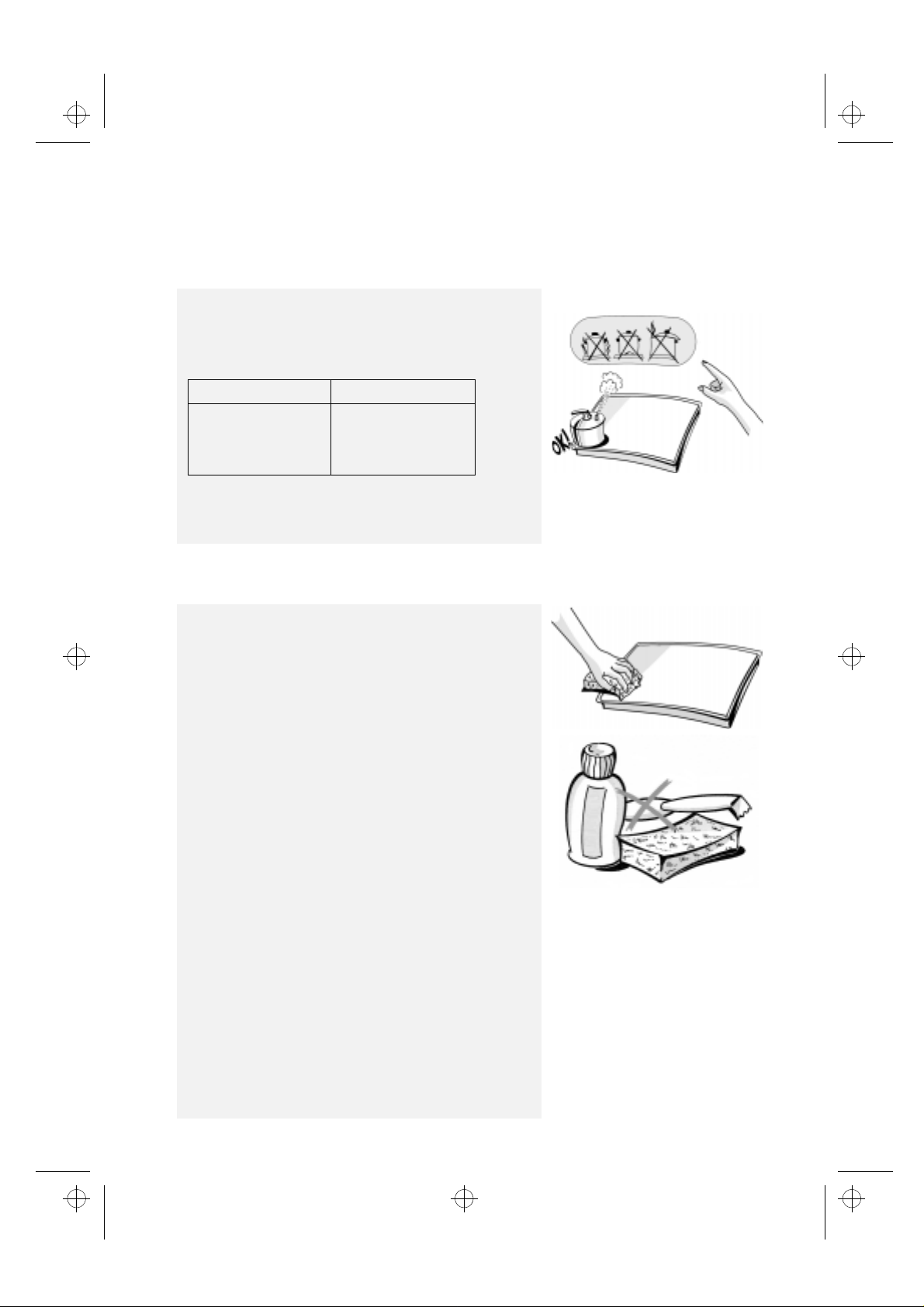
CARE AND MAINTENANCE
Cleaning the cooktop surface, panstand grids and
control panel
• Before cleaning the cooktop, disconnect it from mains
power supply and wait until it has cooled down.
Wipe with a cloth moistened with hot water and soap or
•
diluted liquid detergent.
Do not use abrasive or corrosive products, chlorine products
•
or steel wool.
Do not use vapour cleaning appliances.
•
Do not use flammable products.
•
Do not leave acid or alkaline substances, such as vinegar, salt
•
or lemon juice, etc., on the cooktop.
Stainless steel surface
Clean with a specific commercial product.
•
Note: if the cooktop is used continuously, the high
temperatures produced by the flames may alter the
colour of the surface near the burners.
Cleaning the burners
1. Raise the cap and remove it.
2. Extract the burner from its housing by pulling it up.
3. Soak the burner and the cap in hot water and liquid detergent.
(Do not wash into a dishwasher).
4. Rinse out and dry carefully.
5. Ensure that none of its openings is clogged.
6. Reposition the burner and cap.
Note: to avoid damaging the electric ignition device, do
not use it when the burners are not in their housing.
Cleaning the electric hotplate
The electric hotplate must be cleaned when it is lukewarm.
Wipe with a cloth moistened with water and salt, and polish with
a cloth moistened with oil.
13
Page 4

6gb61801b.fm5 Page 14 Friday, April 11, 2003 2:44 PM
TROUBLESHOOTING GUIDE
1. The burner fails to ignite:
Is the main gas delivery valve open?
•
Has the delivery of the town gas (methane) been
•
suspended?
Is the gas cylinder (liquid gas) empty?
•
Are the openings of the burner clogged?
•
Have the cap and burner been positioned
•
correctly after cleaning?
(See paragraph “Care and maintenance”.)
AFTER SALES SERVICE
Before you call the After Sales Service:
Check the “Troubleshooting guide” above to
1.
see if you can eliminate the trouble yourself.
Re-start the cooktop, to check whether correct
2.
operation has been restored.
If the malfunction persists, call the After Sales
3.
Service.
Give the following information:
type of malfunction;
•
model of cooktop;
•
service number (i.e., the number that follows
•
the word SERVICE on the rating plate under
the cooktop and on the guarantee paper);
your complete address;
•
your telephone number and area code.
•
2. The burner fails to remain lit:
Repeat the ignition operation, turning the knob
•
to the position with the small flame symbol .
3. The electric ignition device does not work:
Is there a power failure?
•
If any repairs are required, please contact
authorised After-Sales Service,
the warranty.
In the unlikely event that an operation or repair is
carried out by an
always request a certification of the job carried out
and insist on the use of
Failure to comply with these instructions may
compromise the safety and quality of the
product.
unauthorised technician,
original spare parts
an
as indicated in
.
14
Page 5

6gb61801b.fm5 Page 15 Friday, April 11, 2003 2:44 PM
INSTALLATION
Technical information for the Installer
This cooktop can be embedded in a worktop 20 to 50 mm
thick. If there is no oven beneath the cooktop (any oven
installed must be manufactured by us and equipped with
a cooling system), insert a separator panel at a minimum
distance of 20 mm from the bottom of the cooktop.
Note: before installation, make sure that the local gas
delivery conditions (nature and pressure of gas) are
compatible with the settings of the cooktop, as indicated
on the Product Description Sheet and on the rating plate.
• If a vertical piece of furniture is installed, there must be
a gap of at least 100 mm between it and the edge of the
cooktop.
Before installation, remove the plastic film protecting the
•
appliance, if provided.
The outer surfaces of the furniture or appliances adjacent to
the cooktop must be heat resistant (heat protection
according to standards.
Installation must comply with current local regulations.
•
In the room where the cooktop is installed, there must be
•
enough air to allow the gas to burn correctly
(see the separate Product Description Sheet).
The natural flow of air must take place through an adequate
•
opening, that must be:
- permanent, made on one of the outside walls of the room,
and communicating with the exterior in an area away from
sources of pollution;
- built so as to ensure that its openings, both on the inside and
on the outside, cannot be obstructed, intentionally or
accidentally;
- protected by a metal grid or mesh that does not reduce its
working section;
- situated near the floor level and positioned so as not to
interfere with the operation of the fume exhaust devices.
- The fume exhaust has to take place through an appropriate
hood or fan installed on the wall or on the window.
Assembly
• Apply the supplied gasket to the cooktop (if not yet
fitted), after having cleaned its surface as shown in the
relevant figure.
To secure the cooktop, use brackets
Fit the brackets into the relevant bores and fasten them by
1.
means of their screws.
Make an opening in the worktop, respecting the dimensions
2.
indicated in the enclosed Product Description Sheet.
Install the cooktop in the worktop.
3.
Important: the power supply cable and plug must be
suitable for the power absorption of the cooktop, and the
cable must be long enough to permit its upward
extraction.
supplied with it.
“A”
“Y”
)
15
Page 6

6gb61801b.fm5 Page 16 Friday, April 11, 2003 2:44 PM
INSTALLATION
Only for GERMANY, SWITZERLAND AND AUSTRIA
A) If the worktop is made out of wood
Fit the four springs
1.
Make an opening in the worktop, according to the dimensions
2.
indicated in the enclosed Product Description Sheet.
Install the cooktop in the worktop.
3.
B) If the worktop is made out of marble or other
materials (plastics, ceramics or stone),
of brackets
from the After Sales Service (code 4819 310 18528).
(see figure on previous page), to be ordered
(A)
into the relative seat under the box.
(B)
, use the springs provided.
fix the hob by means
Electrical and mechanical connection
• The electrical connections must comply with local
regulations.
The data relevant to the voltage and power absorption are
•
indicated on the rating plate.
• The earthing of this appliance is compulsory by law.
• The manufacturer cannot be held responsible for any
injury to persons or animals or damage to property
arising from failure to comply with these requirements.
• When the cooktop is installed, provide a single-pole circuit
breaker with a contact separation of at least 3 mm.
Connection to gas supply
The gas supply system must comply with local regulations.
You can find specific local regulations for some countries, in the
separate National Safety Regulations Sheet supplied.
If no information concerning your Country is given, please ask
details to your Installer.
The connection of the cooktop to the gas pipe network or gas
cylinder must be made by means of a rigid copper or steel pipe
with fittings complying with local regulations, or by means of a
continuous-surface stainless steel hose complying with local
regulations. Interpose gasket
The maximum length of the hose is 2 m.
ONLY FOR BELGIUM:
It is necessary to replace the elbow connection (A) on the
appliance, with the one supplied.
Important: if a stainless steel hose is used, it must be installed
so as not to touch any mobile part of the furniture. It must
pass through an area where there are no obstructions and
where it is possible to inspect it on all its length.
After connection to the gas supply, check for leaks with
soapy water.
CONNECTION AND INSTALLATION
Oven - Cooktop with universal joints
After having installed and fixed the cooktop, install the oven. See
the oven instructions booklet.
Connect tongues
1.
If the cooktop is equipped with an electric hotplate, connect
2.
3-plug assembly
terminal board on block
Position the oven and fix it with the screws supplied.
3.
Fit the knobs, pressing them into their seats on the control panel.
4.
Note: If the cooktop must be connected to a control box,
instead of the connection to the oven, please read
carefully the instructions supplied with the control box.
(A)
to the first 3 bores of the 5 pole
(R)
in the elbow connection
“B”
to end
as shown in the figure.
(B)
as shown in the figure.
(A)
“A”
.
16
Page 7

6gb61801b.fm5 Page 17 Friday, April 11, 2003 2:44 PM
INSTALLATION
OVEN/COOKTOP DIRECT GAS CONNECTION
(please refer carefully to the separate oven instructions
for use)
Slacken the screws
1.
a way that the taps are aligned with the oven knobs.
Adjust the height of the tap bracket
2.
position (2,3,4,5) indicated on the brackets
adjusted to the correct height, tighten the screws
Use the screws
3.
bracket
to the oven panel. Fit the knobs.
(C)
ADJUSTMENT TO DIFFERENT TYPES OF GAS
If a different type of gas to the type shown on the rating plate and
on the orange sticker affixed to the top of the cooktop is used, the
cooktop must be converted to work with the new gas type.
Remove the orange sticker and affix it to the instructions booklet,
which must be retained for the lifetime of the appliance.
Use pressure regulators suitable for the gas pressures
indicated in the separate Product Description Sheet.
The gas nozzles must be changed by After Sales Service or a
1.
qualified technician. Nozzles not supplied with the appliance
must be ordered from After Sales Service.
Connect the cooktop to the gas shut-off valve by means of a
2.
pipe suitable for the type of gas used, in compliance with
current local regulations.
Adjust the minimum setting of the taps.
3.
when liquid petroleum gas is used (G30/G31), the
Note:
minimum gas setting screws must be fully tightened.
off and position the cooktop in such
(A)
according to the
(C)
provided, to secure the cooktop taps
(B)
(D)
. Once
(A)
.
d
n
i
o
l
a
t
a
l
s
t
i
n
n
t
a
t
r
o
I
mp
r
o
f
n
i
o
n
s
i
me
Replacing the injectors
(see table in the separate Product
Description Sheet)
Remove grids
1.
Extract burners
2.
Using a socket spanner of the appropriate size (7)
3.
(A)
(B)
.
.
,
(C)
unscrew the injector to be replaced.
Replace it with the injector suitable for the new type of gas.
4.
Re-assemble the injector in
5.
(D)
.
Adjusting minimum gas setting of taps
To ensure that the minimum setting is correctly adjusted,
1.
remove knob and proceed as follows:
tighten (-) to reduce the height of the flame;
•
loosen (+) to increase the height of the flame;
•
The adjustment must be performed with the tap in minimum gas
setting position (small flame) .
Upon completion of adjustment, reseal using sealing wax or an
equivalent material.
The primary air of the burners does not need to be adjusted.
2.
After the adjustment of the minimum gas setting, light up the
3.
burners and turn the knobs from max. position to min.
position to check the stability of the flame.
17
 Loading...