

Whirlpool YACQ128XR0, ACQL189XS0, ACQL158XS0, ACQL128XS0, ACQ158XS0 Owner’s Manual
...
ROOMAIR
CONDITIONER
y ' .....
For questions about features, operation/performance, parts,
accessories or service call: 1-800-253-1301
or visit our website at... www.whirlpool.com
In Canada, call for assistance, installation and service,
or visit our website at_.www.whirlpool.ca
call: 1-800-807-6777
ACONDICIONADORDE
AIREPARA
HABITACION
1188018B
i, %1/I_i!!=iId ' •
Si tiene preguntas respecto a las caracterfsticas, funcionamiento,
rendimiento, partes, accesorios o servicio tecnico,
o visite nuestro sito web en... www.whirlpooLcom
Table of Contents/Jndice ............................... 2
e( (so !¢L,IIdI_QO
Ilame al: 1-800-253-1301
TABLEOFCONTENTS
AIR CONDITIONER SAFETY ......................................................... 2
INSTALLATION REQUIREMENTS ................................................ 3
Tools and Parts ............................................................................ 3
Location Requirements ................................................................ 3
Electrical Requirements ............................................................... 4
INSTALLATION INSTRUCTIONS .................................................. 5
Unpack the Air Conditioner .......................................................... 5
Window Installation ...................................................................... 6
Prepare Air Conditioner for Window Installation ......................... 8
Position the Air Conditioner in Window ....................................... 9
Through-the-Wall Installation ..................................................... 10
Position the Air Conditioner Through the Wall .......................... 13
AIR CONDITIONER USE .............................................................. 14
Start Your Air Conditioner-- Digital Control ............................... 15
J
INDICE
SEGURIDAD DEL ACONDICIONADOR DE hIRE ...................... 22
REQUISITOS DE INSTALACION ................................................. 23
Herramientas y piezas ................................................................ 23
Requisites de ubicaci6n ............................................................. 23
Requisites electricos .................................................................. 24
INSTRUCCIONES DE INSTALACION ......................................... 25
Desempaque el acondicionador de aire .................................... 25
Instalaci6n en la ventana ............................................................ 26
Prepare el acondicionador de aire para la instalaci6n
en una ventana ........................................................................... 28
Colocaci6n del acondicionador de aire en la ventana .............. 29
Instalaci6n a traves de la pared ................................................. 31
Colocaci6n del acondicionador de aire para la instalaci6n
a traves de la pared .................................................................... 34
COMO USAR SU ACONDICIONADOR DE AIRE ....................... 36
Start Your Air Conditioner--Rotary Control ............................... 18
Change Air Direction .................................................................. 19
Normal Sounds ........................................................................... 19
AIR CONDITIONER CARE ........................................................... 19
Cleaning the Air Filter ................................................................. 19
Cleaning the Front Panel ............................................................ 19
Repairing Paint Damage ............................................................ 19
Annual Maintenance ................................................................... 19
TROUBLESHOOTING .................................................................. 20
ASSISTANCE OR SERVICE ......................................................... 21
In the U.S.A................................................................................ 21
Accessories ................................................................................ 21
In Canada ................................................................................... 22
C6mo poner en marcha su acondicionador de aire--
Control digital ............................................................................. 36
C6mo poner en marcha su acondicionador de aire--
Control rotativo ........................................................................... 39
C6mo cambiar la direcci6n del aire ........................................... 40
Sonidos normales ....................................................................... 40
COMO CUIDAR SU ACONDICIONADOR DE hIRE ................... 41
Limpieza del filtro de aim ........................................................... 41
Limpieza del panel delantero ..................................................... 41
Reparaci6n de la pintura da_ada ............................................... 41
Mantenimiento anual .................................................................. 41
SOLUClON DE PROBLEMAS ...................................................... 41
AYUDA O SERVIClO TI_CNICO ................................................... 43
En los EE.UU.............................................................................. 43
Accesorios .................................................................................. 43
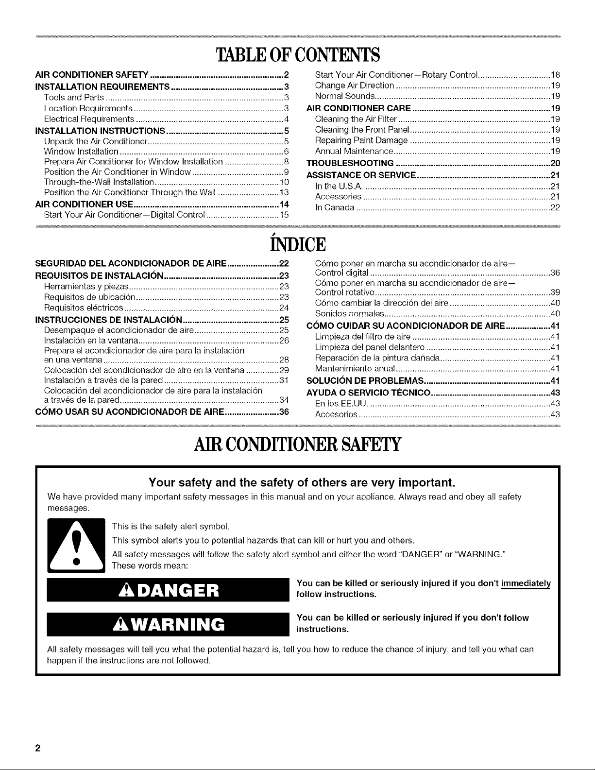
AIRCONDITIONERSAFETY
Your safety and the safety of others are very important.
We have provided many important safety messages in this manual and on your appliance. Always read and obey all safety
messages.
This is the safety alert symbol.
This symbol alerts you to potential hazards that can kill or hurt you and others.
All safety messages will follow the safety alert symbol and either the word "DANGER" or "WARNING."
These words mean:
You can be killed or seriously injured if you don't immediately
follow instructions.
You can be killed or seriously injured if you don't follow
instructions.
All safety messages will tell you what the potential hazard is, tell you how to reduce the chance of injury, and tell you what can
happen if the instructions are not followed.
IMPORTANT SAFETY INSTRUCTIONS
WARN ING: To reduce the risk of fire, electrical shock or injury when using your air conditioner, follow these basic precautions:
• Plug into a grounded 3 prong outlet.
• Do not use an extension cord.
• Do not remove ground prong.
• Do not use an adapter.
SAVE TH ESE INSTRUCTIONS
INSTALLATIONREQUIREMENTS
Gather the required tools and parts before starting installation.
Read and follow the instructions provided with any tools listed
here.
Tools Needed
• Flat-blade and Phillips
screwdrivers
• 1/4"nut driver
• 7/16" wrench
• Scissors
Through-the-Wall Installation
In addition to the tools listed above, the following tools are
needed for through-the-wall installation.
• Saw • Caulk
• Wood preservative • 1" (2.5 cm) or thicker
• Pencil
• Tape measure
• Level
• Drill
• %2" or smaller drill bit
lumber
• Unplug air conditioner before servicing.
• Use two or more people to move and install air conditioner.
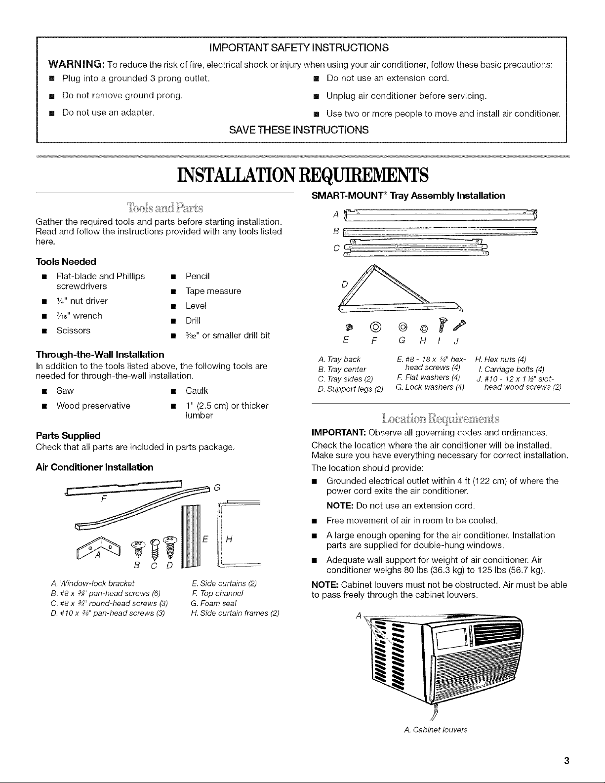
SMART-MOUNT _ Tray Assembly Installation
A_ °
B _ 4
E F G H / J
A. Tray back
B. Tray center
C. Tray sides (2)
D. Support legs (2)
E.#8-18x _"hex- H. Hexnuts(4)
head screws (4) L Carriage bolts (4)
F. Flatwashers(4) J.#10-12x1½"slot-
G. Lock washers (4) head wood screws (2)
Parts Supplied
Check that all parts are included in parts package.
Air Conditioner Installation
i
B C D
A. Window-lock bracket
B. #8 x _" pan-head screws (6)
C. #8 x _" round-head screws (3)
D. #10 x _" pan-head screws (3)
E.Side curtains (2)
F. Top channel
G. Foam seal
H. Side curtain frames (2)
IMPORTANT: Observe all governing codes and ordinances.
Check the location where the air conditioner will be installed.
Make sure you have everything necessary for correct installation.
The location should provide:
• Grounded electrical outlet within 4 ft (122 cm) of where the
power cord exits the air conditioner.
NOTE: Do not use an extension cord.
• Free movement of air in room to be cooled.
• A large enough opening for the air conditioner. Installation
parts are supplied for double-hung windows.
• Adequate wall support for weight of air conditioner. Air
conditioner weighs 80 Ibs (36.3 kg) to 125 Ibs (56.7 kg).
NOTE: Cabinet louvers must not be obstructed. Air must be able
to pass freely through the cabinet louvers.
A. Cabinet louvers
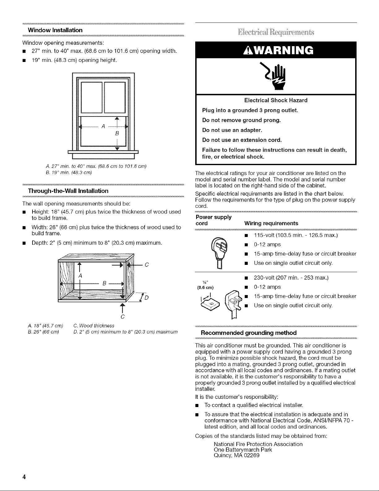
Window Installation
Window opening measurements:
• 27" min. to 40" max. (68.6 cm to 101.6 cm) opening width.
• 19" min. (48.3 cm) opening height.
B
h
I J
A.27" min. to 40" max. (68.6cm to 101.6 cm)
B. 19" min. (48.3 cm)
Through-the-Wall Installation
The wall opening measurements should be:
• Height: 18" (45.7 cm) plus twice the thickness of wood used
to build frame.
• Width: 26" (66 cm) plus twice the thickness of wood used to
build frame.
• Depth: 2" (5 cm) minimum to 8" (20.3 cm) maximum.
V
Electrical Shock Hazard
Plug into a grounded 3 prong outlet.
Do not remove ground prong.
Do not use an adapter.
Do not use an extension cord,
Failure to follow these instructions can result in death,
fire, or electrical shock.
The electrical ratings for your air conditioner are listed on the
model and serial number label. The model and serial number
label is located on the right-hand side of the cabinet.
Specific electrical requirements are listed in the chart below.
Follow the requirements for the type of plug on the power supply
cord.
Power supply
cord Wiring requirements
• 115-volt (103.5 min. - 126.5 max.)
• 15-amp time-delay fuse or circuit breaker
• 0-12 amps
• Use on single outlet circuit only.
c
t
C
A. 18" (45.7cm) C. Wood thickness
B.26" (66 cm) D. 2" (5 cm)minimum to 8" (20.3 cm)maximum
• 230-volt (207 min. - 253 max.)
(0.6cm) • 0-12 amps
_'_ • 15-amp time-delay fuse or circuit breaker
Recommended grounding method
This air conditioner must be grounded. This air conditioner is
equipped with a power supply cord having a grounded 3 prong
plug. To minimize possible shock hazard, the cord must be
plugged into a mating, grounded 3 prong outlet, grounded in
accordance with all local codes and ordinances. If a mating outlet
is not available, it is the customer's responsibility to have a
properly grounded 3 prong outlet installed by a qualified electrical
installer.
It is the customer's responsibility:
• To contact a qualified electrical installer.
• To assure that the electrical installation is adequate and in
conformance with National Electrical Code, ANSI/NFPA 70 -
latest edition, and all local codes and ordinances.
Copies of the standards listed may be obtained from:
National Fire Protection Association
One Batterymarch Park
Quincy, MA 02269
• Use on single outlet circuit only.
Power Supply Cord
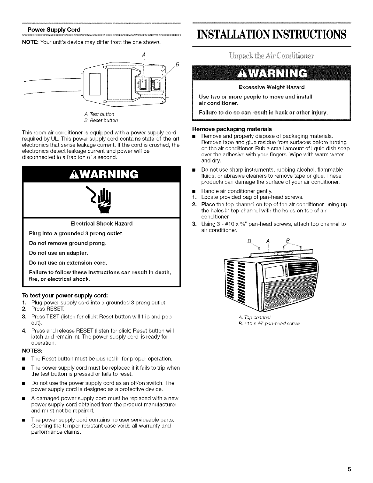
NOTE: Yourunit's device may differ from the one shown.
A
A. Test button
B. Reset button
This room air conditioner is equipped with a power supply cord
required by UL. This power supply cord contains state-of-the-art
electronics that sense leakage current. If the cord is crushed, the
electronics detect leakage current and power will be
disconnected in a fraction of a second.
Electrical Shock Hazard
Plug into a grounded 3 prong outlet.
Do not remove ground prong.
Do not use an adapter.
Do not use an extension cord.
Failure to follow these instructions can result in death,
fire, or electrical shock.
INSTALLATIONINSTRUCTIONS
Excessive Weight Hazard
Use two or more people to move and install
air conditioner.
Failure to do so can result in back or other injury.
Remove packaging materials
• Remove and properly dispose of packaging materials.
Remove tape and glue residue from surfaces before turning
on the air conditioner. Rub a small amount of liquid dish soap
over the adhesive with your fingers. Wipe with warm water
and dry.
Do not use sharp instruments, rubbing alcohol, flammable
fluids, or abrasive cleaners to remove tape or glue. These
products can damage the surface of your air conditioner.
• Handle air conditioner gently.
1. Locate provided bag of pan-head screws.
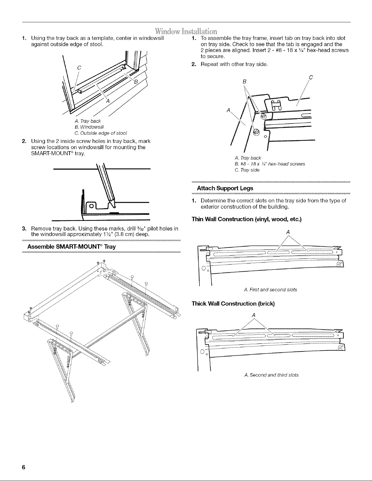
2. Place the top channel on top of the air conditioner, lining up
the holes in top channel with the holes on top of air
conditioner.
3. Using 3 - #10 x %" pan-head screws, attach top channel to
air conditioner.
B A B
To test your power supply cord:
1. Plug power supply cord into a grounded 3 prong outlet.
2. Press RESET.
3. Press TEST (listen for click; Reset button will trip and pop
out).
4. Press and release RESET (listen for click; Reset button will
latch and remain in). The power supply cord is ready for
operation.
NOTES:
• The Reset button must be pushed in for proper operation.
• The power supply cord must be replaced if it fails to trip when
the test button is pressed or fails to reset.
• Do not use the power supply cord as an off/on switch. The
power supply cord is designed as a protective device.
• A damaged power supply cord must be replaced with a new
power supply cord obtained from the product manufacturer
and must not be repaired.
• The power supply cord contains no user serviceable parts.
Opening the tamper-resistant case voids all warranty and
performance claims.
A. Top channel
B. #10 x _" pan-head screw
Using the tray back as a template, center in windowsill
against outside edge of stool.
/
A. Trayback
B.Windowsill
C. Outside edge of stool
2=
Using the 2 inside screw holes in tray back, mark
screw locations on windowsill for mounting the
SMART-MOUNT _tray.
1. To assemble the tray frame, insert tab on tray back into slot
on tray side. Check to see that the tab is engaged and the
2 pieces are aligned. Insert 2 - #8 - 18 x 1/4"hex-head screws
to secure.
2. Repeat with other tray side.
C
A. Tray back
B. #8 - 18 x _" hex-head screws
C. Tray side
Attach Support Legs
1. Determine the correct slots on the tray side from the type of
exterior construction of the building.
3. Remove tray back. Using these marks, drill %2" pilot holes in
the windowsill approximately 11/2"(3.8 cm) deep.
Assemble SMART-MOUNT _Tray
Thin Wall Construction (vinyl,wood, etc.)
A.First and second slots
Thick Wall Construction (brick}
A
A. Second and third slots
2=
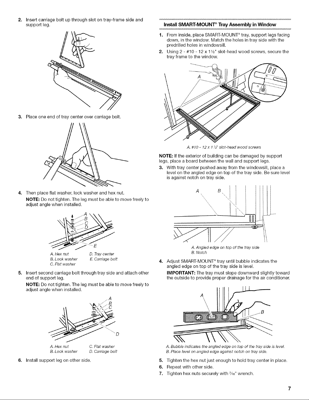
Insert carriage bolt up through slot on tray-frame side and
support leg. Install SMART-MOUNT _ Tray Assembly in Window
1. From inside, place SMART-MOUNT _tray, support legs facing
down, in the window. Match the holes in tray side with the
predrilled holes in windowsill.
2. Using 2 - #10 - 12 x 11/2"slot-head wood screws, secure the
tray frame to the window.
3. Place one end of tray center over carriage bolt.
A. #10 - 12 x 1_" slot-head wood screws
NOTE: If the exterior of building can be damaged by support
legs, place a board between the wall and support legs.
3. With tray center pushed away from the windowsill, place a
level on the angled edge on top of the tray side. Be sure level
is against notch on tray side.
4=
Then place flat washer, lock washer and hex nut.
NOTE: Do not tighten. The leg must be able to move freely to
adjust angle when installed.
.A
A. Hex nut D. Tray center
B. Lock washer E. Carriage bolt
C. Flat washer
5=
Insert second carriage bolt through tray side and attach other
end of support leg.
NOTE: Do not tighten. The leg must be able to move freely to
adjust angle when installed.
s A
A B
A.Angled edge on top of the tray side
B. Notch
4=
Adjust SMART-MOUNT _ tray until bubble indicates the
angled edge on top of the tray side is level.
IMPORTANT: The tray must slope downward slightly toward
the outside to provide proper drainage for the air conditioner.
A. Hex nut C. Flat washer
B. Lock washer D. Carriage bolt
6. Install support leg on other side.
A. Bubble indicates theangled edge on top of the tray side is level.
B.Place level on angled edge against notch on tray side.
5. Tighten the hex nut just enough to hold tray center in place.
6. Repeat with other side.
7. Tighten hex nuts securely with 7A6"wrench.
Install Side Curtains
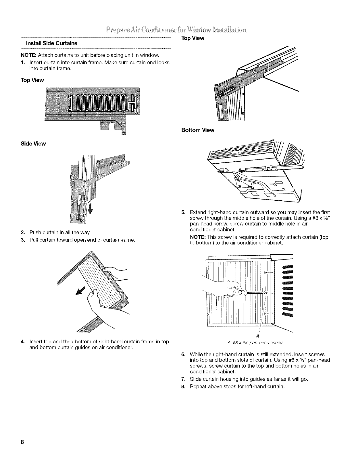
NOTE: Attach curtains to unit before placing unit in window.
1. Insert curtain into curtain frame. Make sure curtain end locks
into curtain frame.
TopView
Side View
TopView
Bottom View
2. Push curtain in all the way.
3. Pull curtain toward open end of curtain frame.
4.
Insert top and then bottom of right-hand curtain frame in top
and bottom curtain guides on air conditioner.
5=
Extend right-hand curtain outward so you may insert the first
screw through the middle hole of the curtain. Using a #8 x %"
pan-head screw, screw curtain to middle hole in air
conditioner cabinet.
NOTE: This screw is required to correctly attach curtain (top
to bottom) to the air conditioner cabinet.
i m
A
A.#8 x _" pan-head screw
6. While the right-hand curtain is still extended, insert screws
into top and bottom slots of curtain. Using #8 x %" pan-head
screws, screw curtain to the top and bottom holes in air
conditioner cabinet.
7. Slide curtain housing into guides as far as it will go.
8. Repeat above steps for left-hand curtain.
• Handleairconditionergently.
• Be sure your air conditioner does not fall out of the opening
during installation or removal.
• Do not block the louvers on the front panel.
• Do not block the louvers on the outside of the air conditioner.
Excessive Weight Hazard
Use two or more people to move and install
air conditioner.
Failure to do so can result in back or other injury.
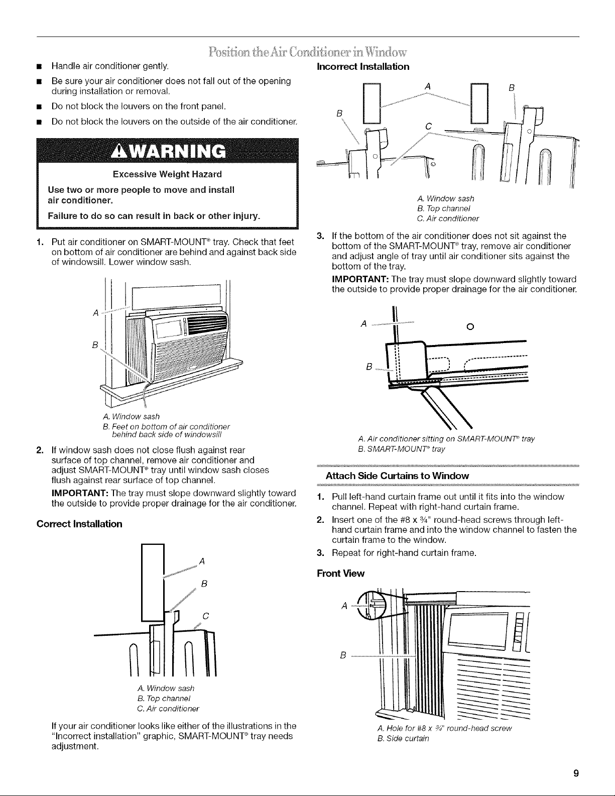
1. Put air conditioner on SMART-MOUNT _tray. Check that feet
on bottom of air conditioner are behind and against back side
of windowsill. Lower window sash.
A _
B
Incorrect Installation
A. Window sash
B. Top channel
C. Air conditioner
3.
If the bottom of the air conditioner does not sit against the
bottom of the SMART-MOUNT ° tray, remove air conditioner
and adjust angle of tray until air conditioner sits against the
bottom of the tray.
IMPORTANT: The tray must slope downward slightly toward
the outside to provide proper drainage for the air conditioner.
O
A. Window sash
B.Feet on bottom of air conditioner
behind back side of windowsill
2.
If window sash does not close flush against rear
surface of top channel, remove air conditioner and
adjust SMART-MOUNT ®tray until window sash closes
flush against rear surface of top channel.
IMPORTANT: The tray must slope downward slightly toward
the outside to provide proper drainage for the air conditioner.
Correct Installation
B
E A
A. Window sash
B. Top channel
C. Air conditioner
A. Air conditioner sitting on SMART-MOUNT _tray
B. SMART-MOUNT _ tray
Attach Side Curtains to Window
1. Pull left-hand curtain frame out until it fits into the window
channel. Repeat with right-hand curtain frame.
2. Insert one of the #8 x %" round-head screws through left-
hand curtain frame and into the window channel to fasten the
curtain frame to the window.
3. Repeat for right-hand curtain frame.
Front View
A "_
B
If your air conditioner looks like either of the illustrations in the
"Incorrect installation" graphic, SMART-MOUNT ° tray needs
adjustment.
A.Hole for #8 x _" round-head screw
B.Side curtain
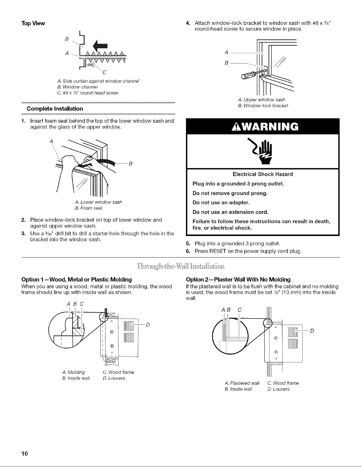
TopView
,'
A. Side curtain against window channel
B. Window channel
C. #8 x ¾" round-head screw
Complete Installation
1. Insert foam seal behind the top of the lower window sash and
against the glass of the upper window.
A. Lower window sash
B. Foam seal
2. Place window-lock bracket on top of lower window and
against upper window sash.
3. Use a 3/_,, drill bit to drill a starter hole through the hole in the
bracket into the window sash.
4= Attach window-lock bracket to window sash with #8 x 3/4"
round-head screw to secure window in place.
A. Upper window sash
B. Window-lock bracket
Electrical Shock Hazard
Plug into a grounded 3 prong outlet.
Do not remove ground prong.
Do not use an adapter.
Do not use an extension cord.
Failure to follow these instructions can result in death,
fire, or electrical shock.
5. Plug into a grounded 3 prong outlet.
6. Press RESET on the power supply cord plug.
Option 1--Wood, Metal or Plastic Molding
When you are using a wood, metal or plastic molding, the wood
frame should line up with inside wall as shown.
ABC
L
i ]}}
A. Molding
B. Inside wall
C. Wood frame
D. Louvers
Option 2--Plaster Wall With No Molding
If the plastered wall is to be flush with the cabinet and no molding
is used, the wood frame must be set _/2"(13 mm) into the inside
wall.
AB C
A. Plastered wall C. Wood frame
B. Inside wall D. Louvers
10
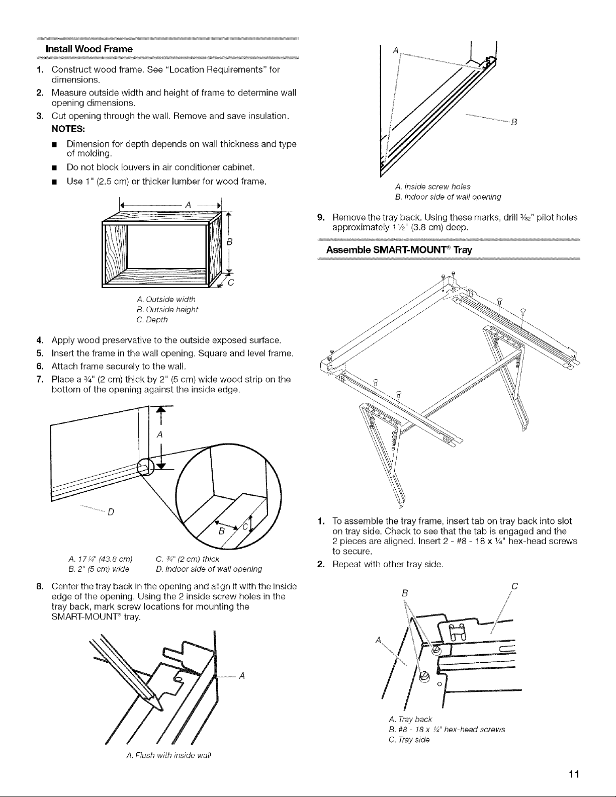
Install Wood Frame
1. Construct wood frame. See "Location Requirements" for
dimensions.
2. Measure outside width and height of frame to determine wall
opening dimensions.
3. Cut opening through the wall. Remove and save insulation.
NOTES:
• Dimension for depth depends on wall thickness and type
of molding.
• Do not block louvers in air conditioner cabinet.
• Use 1" (2.5 cm) or thicker lumber for wood frame.
A -_
B
A. Outside width
B. Outside height
C. Depth
4. Apply wood preservative to the outside exposed surface.
5. Insert the frame in the wall opening. Square and level frame.
6. Attach frame securely to the wall.
7. Place a 3/4"(2 cm) thick by 2" (5 cm) wide wood strip on the
bottom of the opening against the inside edge.
A. Inside screw holes
B. Indoor side of wall opening
9. Remove the tray back. Using these marks, drill %2" pilot holes
approximately 11/2"(3.8 cm) deep.
Assemble SMART-MOUNT _Tray
A. 17¼" (43.8 cm)
B. 2" (5 cm) wide
8=
Center the tray back in the opening and align it with the inside
C. _" (2 cm) thick
D. Indoor side of wall opening
edge of the opening. Using the 2 inside screw holes in the
tray back, mark screw locations for mounting the
SMART-MOUNT _tray.
A. Flush with inside wall
1. To assemble the tray frame, insert tab on tray back into slot
on tray side. Check to see that the tab is engaged and the
2 pieces are aligned. Insert 2 - #8 - 18 x 1/4"hex-head screws
to secure.
2. Repeat with other tray side.
C
A. Tray back
B. #8 - 18 x _" hex-head screws
C. Tray side
11
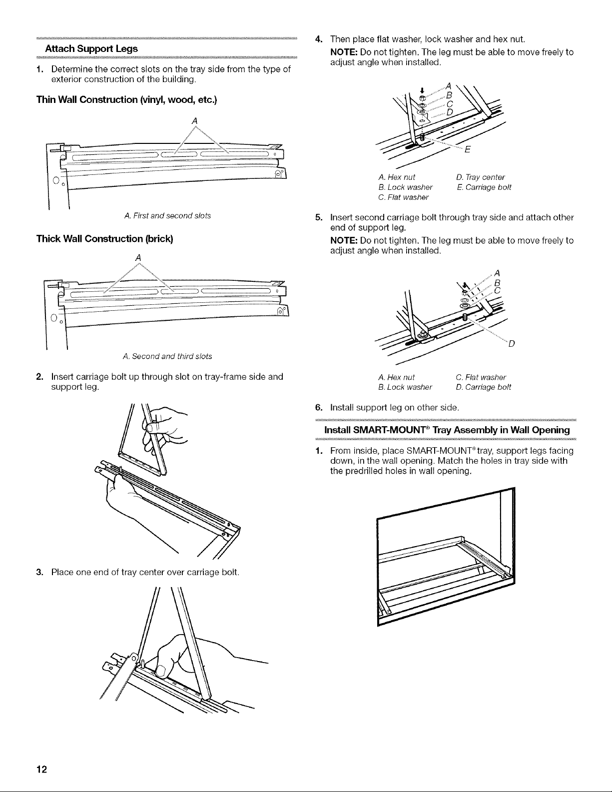
Attach Support Legs
1. Determine the correct slots on the tray side from the type of
exterior construction of the building.
Thin Wall Construction (vinyl, wood, etc.)
A
4. Then place flat washer, lock washer and hex nut.
NOTE: Do not tighten. The leg must be able to move freely to
adjust angle when installed.
.......A
,,_s,, y,, C
......iii:ii:...........
A. Hex nut D. Tray center
B. Lock washer E. Carriage bolt
C. Flat washer
A.First and second slots
Thick Wall Construction (brick}
A
A. Second and third slots
2. Insert carriage bolt up through slot on tray-frame side and
support leg.
5=
Insert second carriage bolt through tray side and attach other
end of support leg.
NOTE: Do not tighten. The leg must be able to move freely to
adjust angle when installed.
......A
..........
o
_D
A. Hex nut C. Flat washer
B. Lock washer D. Carriage bolt
6. Install support leg on other side.
Install SMART-MOUNT _ Tray Assembly in Wall Opening
1. From inside, place SMART-MOUNT_tray, support legs facing
down, in the wall opening. Match the holes in tray side with
the predrilled holes in wall opening.
3. Place one end of tray center over carriage bolt.
12
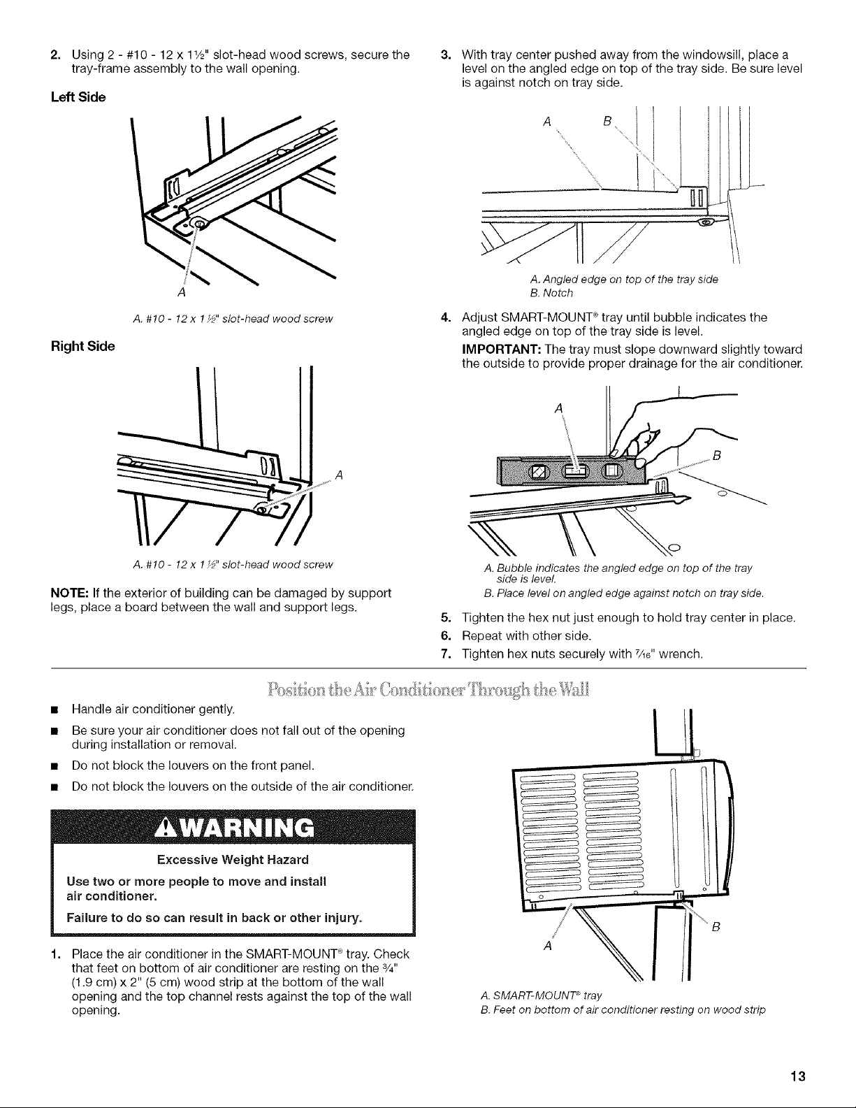
2. Using 2 - #10 - 12 x 11/2"slot-head wood screws, secure the
tray-frame assembly to the wall opening.
Left Side
3=
With tray center pushed away from the windowsill, place a
level on the angled edge on top of the tray side. Be sure level
is against notch on tray side.
A.Angled edge on top of the trayside
B.Notch
A. #10 - 12 x 1_" slot-head wood screw
Right Side
A
A.#10 - 12x 1_" slot-head wood screw
NOTE: If the exterior of building can be damaged by support
legs, place a board between the wall and support legs.
• Handle air conditioner gently.
• Be sure your air conditioner does not fall out of the opening
during installation or removal.
• Do not block the louvers on the front panel.
• Do not block the louvers on the outside of the air conditioner.
4.
Adjust SMART-MOUNT _ tray until bubble indicates the
angled edge on top of the tray side is level.
IMPORTANT: The tray must slope downward slightly toward
the outside to provide proper drainage for the air conditioner.
A. Bubble indicates the angled edge on top of the tray
side isleveL
B.Place level on angled edge againstnotch on tray side.
5=
Tighten the hex nut just enough to hold tray center in place.
6.
Repeat with other side.
7.
Tighten hex nuts securely with 7_6"wrench.
LJ
Excessive Weight Hazard
Use two or more people to move and install
air conditioner.
Failure to do so can result in back or other injury.
Place the air conditioner in the SMART-MOUNT ° tray. Check
that feet on bottom of air conditioner are resting on the 3/4"
(1.9 cm) x 2" (5 cm) wood strip at the bottom of the wall
opening and the top channel rests against the top of the wall
opening.
A J
-JX,i
A. SMART-MOUNT ®tray
B. Feet on bottom of air conditioner resting on wood strip
13
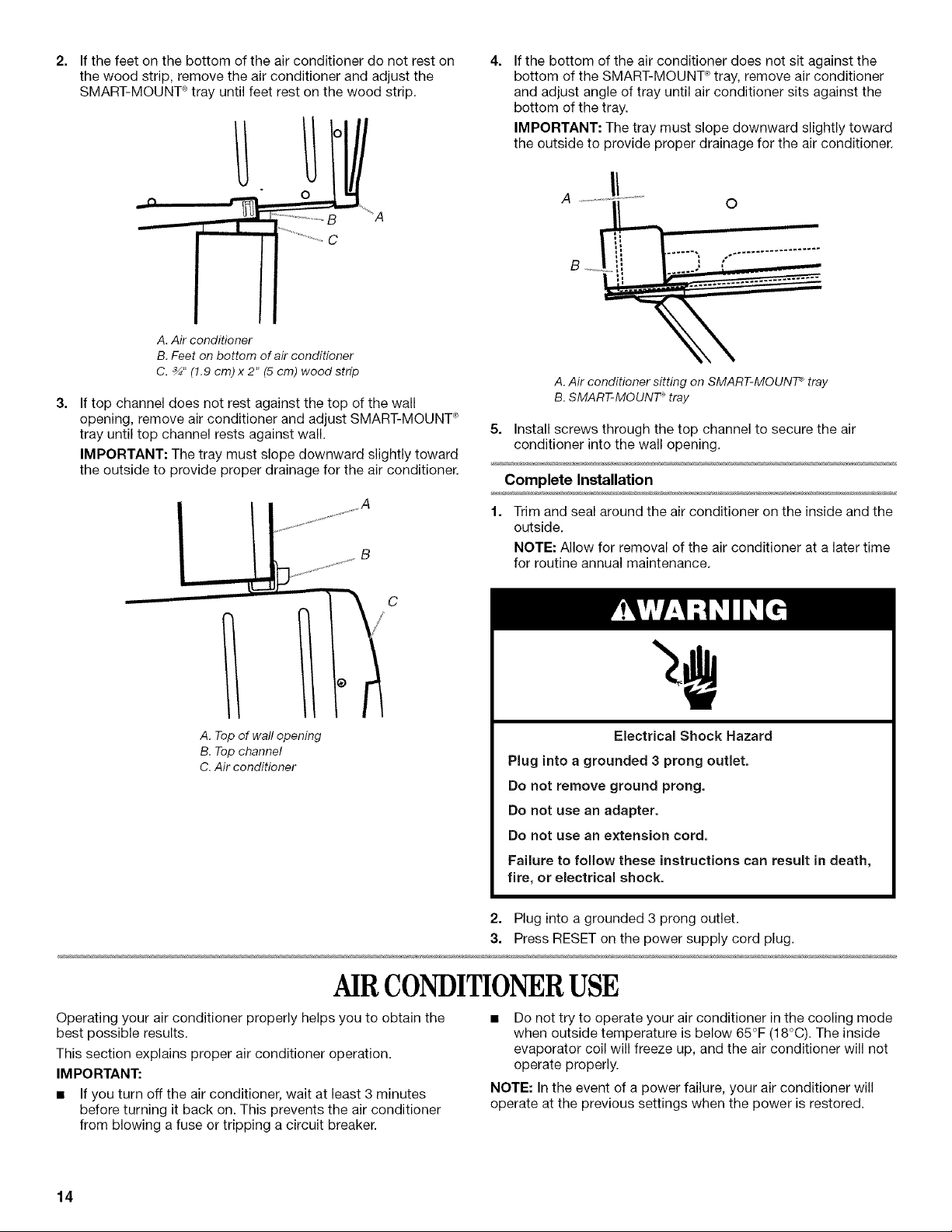
2= If the feet on the bottom of the air conditioner do not rest on
the wood strip, remove the air conditioner and adjust the
SMART-MOUNT _tray until feet rest on the wood strip.
4=
If the bottom of the air conditioner does not sit against the
bottom of the SMART-MOUNT ° tray, remove air conditioner
and adjust angle of tray until air conditioner sits against the
bottom of the tray.
IMPORTANT: The tray must slope downward slightly toward
the outside to provide proper drainage for the air conditioner.
__n
A. Air conditioner
B. Feet on bottom of air conditioner
C. _" (!.9 cm) x 2" (5 cm) wood strip
3=
If top channel does not rest against the top of the wall
J_F* ................. _A
J I
.......................... C
opening, remove air conditioner and adjust SMART-MOUNT _
tray until top channel rests against wall.
IMPORTANT: The tray must slope downward slightly toward
the outside to provide proper drainage for the air conditioner.
B
0
A. Air conditioner sitting on SMART-MOUNT _tray
B. SMART-MOUNT _ tray
5. Install screws through the top channel to secure the air
conditioner into the wall opening.
Complete Installation
1. Trim and seal around the air conditioner on the inside and the
outside.
NOTE: Allow for removal of the air conditioner at a later time
for routine annual maintenance.
A. Top of wall opening
B. Top channel
C. Air conditioner
AIRCONDITIONERUSE
Operating your air conditioner properly helps you to obtain the
best possible results.
This section explains proper air conditioner operation.
IMPORTANT:
• If you turn off the air conditioner, wait at least 3 minutes
before turning it back on. This prevents the air conditioner
from blowing a fuse or tripping a circuit breaker.
Electrical Shock Hazard
Plug into a grounded 3 prong outlet.
Do not remove ground prong.
Do not use an adapter.
Do not use an extension cord,
Failure to follow these instructions can result in death,
fire, or electrical shock.
2. Plug into a grounded 3 prong outlet.
3. Press RESET on the power supply cord plug.
Do not try to operate your air conditioner inthe cooling mode
when outside temperature is below 65°F (18°C). The inside
evaporator coil will freeze up, and the air conditioner will not
operate properly.
NOTE: In the event of a power failure, your air conditioner will
operate at the previous settings when the power is restored.
14
 Loading...