

Whirlpool ACQ304XS1, ACQ304XS0, ACQ249XR2, ACQ249XR1, ACQ249XR0 Owner’s Manual
...
AIRCONDITIONER
For questions about features, operation/performance, parts,
accessories or service, call: 1-800-253-1301 in the U.S.A.
ACONDICIONADOR
Si tiene prsguntas respeeto alas caractsrfstisas, funsionamiento,
rendimiento, partes, ascssorios o servisio teenico,
Ilame al: 1-800-253-1301 en los EE. UU.
Table of Contents/Indice ..................................... 2
1188127A
TABLEOF CONTENTS
AIR CONDITIONER SAFETY ......................................................... 2
INSTALLATION REQUIREMENTS ................................................ 3
Tools and Parts ............................................................................ 3
Location Requirements ................................................................ 3
Electrical Requirements ............................................................... 4
INSTALLATION INSTRUCTIONS .................................................. 5
Unpacking .................................................................................... 5
Installing the Cabinet in a Window .............................................. 6
Installing the Cabinet Through a Wall .......................................... 9
Complete Installation ................................................................. 10
AIR CONDITIONER USE.............................................................. 11
Starting Your Air Conditioner-- Digital Control .......................... 11
iNDICE
SEGURIDAD DEL ACONDICIONADOR DE AIRE ...................... lg
REQUlSITOS DE INSTALACION ................................................. 19
Herramientas y piezas ................................................................ 19
Requisitos de ubicaci6n ............................................................. 20
Requisitos electricos .................................................................. 21
INSTRUCCIONES DE INSTALACION ......................................... 22
Desempaque .............................................................................. 22
Instalaci6n del gabinete en una ventana ................................... 23
Instalaci6n del gabinete a traves de la pared ............................ 25
Para completar la instalaci6n ..................................................... 27
USO DE SU ACONDICIONADOR DE AIRE ................................ 28
C6mo poner en marcha su acondicionador de aire --
Control digital ............................................................................. 29
Starting Your Air Conditioner--Rotary Controls ........................ 14
Changing Air Direction ............................................................... 16
Normal Sounds ........................................................................... 16
AIR CONDITIONER CARE ........................................................... 16
Cleaning the Air Filter ................................................................. 16
Cleaning the Front Panel ............................................................ 16
Repairing Paint Damage ............................................................ 16
Annual Maintenance ................................................................... 16
TROUBLESHOOTING .................................................................. 17
ASSISTANCE OR SERVICE ......................................................... 18
Accessories ................................................................................ 18
C6mo poner en marcha su acondicionador de aire --
Controles rotativos ..................................................................... 32
C6mo cambiar la direcci6n del aire ........................................... 33
Sonidos normales ....................................................................... 33
CUIDADO DE SU ACONDICIONADOR DE AIRE ....................... 34
Limpieza del filtro de aire ........................................................... 34
Limpieza del panel delantero ..................................................... 34
Reparaci6n de la pintura da_ada ............................................... 34
Mantenimiento anual .................................................................. 34
SOLUClON DE PROBLEMAS ...................................................... 34
AYUDA O SERVIClO TI_CNICO ................................................... 36
Accesorios .................................................................................. 36
AIRCONDITIONERSAFETY
Your safety and the safety of others are very important.
We have provided many important safety messages in this manual and on your appliance. Always read and obey all
safety messages.
This symbol alerts you to potential hazards that can kill or hurt you and others.
All safety messages will follow the safety alert symbol and either the word "DANGER" or
This is the safety alert symbol.
"WARNING." These words mean:
You can be killed or seriously injured if you don't
immediately follow instructions.
You can be killed or seriously injured if you don't
follow instructions.
All safety messages will tell you what the potential hazard is, tell you how to reduce the chance of injury, and tell you
what can happen if the instructions are not followed.
IMPORTANT SAFETY INSTRUCTIONS
WARN ING: To reduce the risk of fire, electrical shock or injury when using your air conditioner, follow these basic precautions:
• Plug into a grounded 3 prong outlet.
[] Do not use an extension cord.
[] Do not remove ground prong.
[] Do not use an adapter.
SAVE TH ESE INSTRUCTIONS
INSTALLATIONREQUIREMENTS
Gather the required tools and parts before starting installation.
Read and follow the instructions provided with any tools listed
here.
Tools Needed
• Flat-blade and Phillips
screwdrivers
• Level
• Socket wrench and 7/16"
and 1/4"sockets
• Pencil
Through-the-wall installation:
In addition to the tools listed above, the following tools are
needed for though-the-wall installation.
• Saw • 1" (2.5 cm) or thicker
• Wood preservative
• Caulk • 7-#10xl"woodscrews
• Scissors
• Tape measure
• Drill and ¾£' or smaller bit
• 1/4"nut driver
• Utility knife
lumber
[] Unplug air conditioner before servicing.
[] Use two or more people to move and install air conditioner.
NOTE: Installation parts are supplied for double-hung windows
up to 40" (101.6 cm) wide. A special Wide Window Kit is available
from your dealer or service center. See "Accessories."
IMPORTANT: Observe all governing codes and ordinances.
Check the location where air conditioner will be installed. Proper
installation is your responsibility. Make sure you have everything
necessary for correct installation.
The location should provide:
• Grounded electrical outlet within 4 ft (122 cm) of where the
power cord exits the air conditioner.
NOTE: Do not use an extension cord.
• Free movement of air in room to be cooled.
• A large enough opening for the air conditioner.
• Adequate wall support for weight of air conditioner. Air
conditioner weighs between 145 and 200 Ibs (65 to 96 kg).
NOTES: Cabinet louvers must not be obstructed. Air must be
able to pass freely through the cabinet louvers.
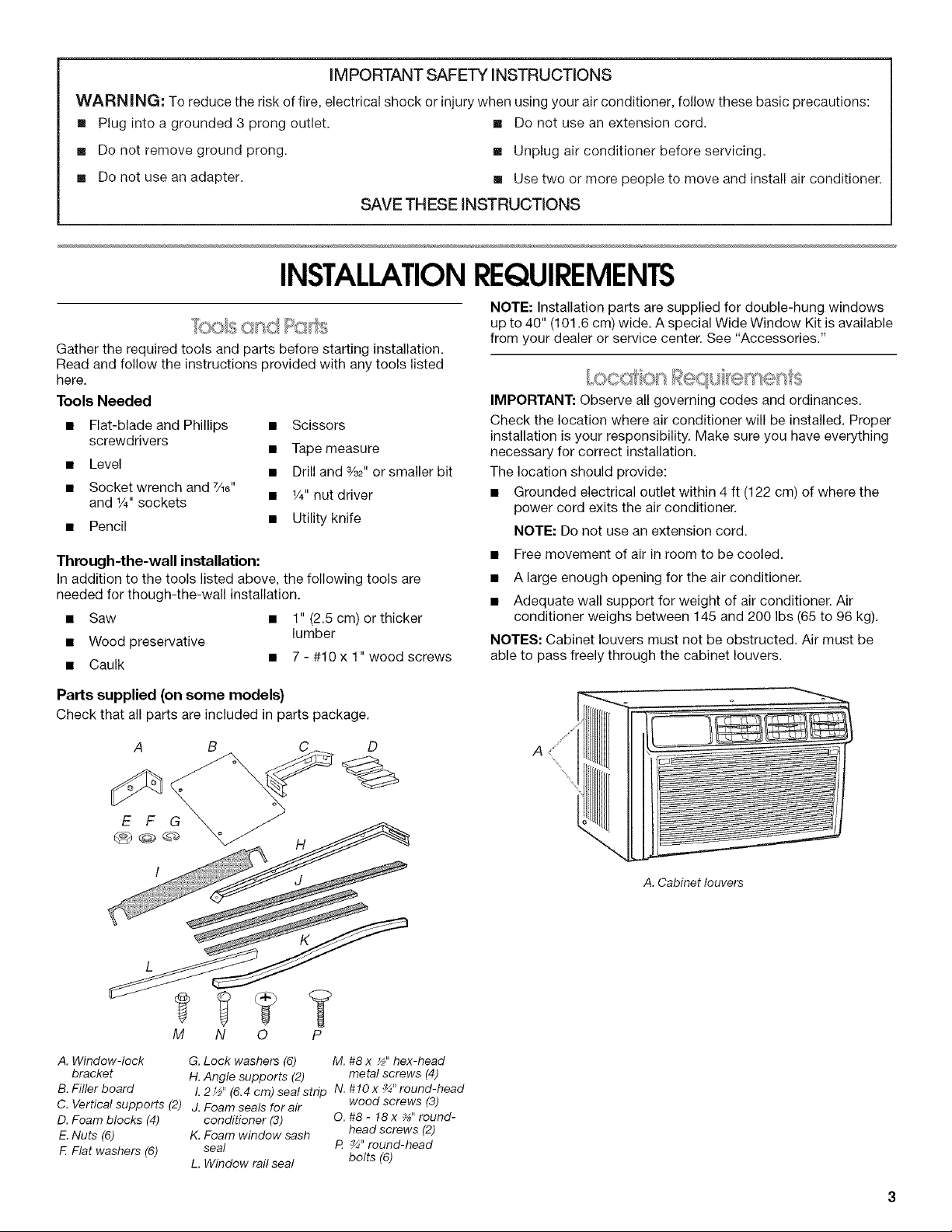
Parts supplied (on some models)
Check that all parts are included in parts package.
E F
M N 0 P
A. Window-lock G. Lock washers (6) M. #8 x ½" hex-head
bracket H. Angle supports (2) metal screws (4)
B. Filler board L 2 _" (6.4 cm) seal strip N. #10 x _" round-head
C. Vertical supports (2) j. Foam seals for air wood screws (3)
D. Foam blocks (4) conditioner (3) O. #8 - 18 x _" round-
E. Nuts (6) K. Foam window sash head screws (2)
F. Flat washers (6) seal t_ _" round-head
L. Window rail seal bolts (6)
A _i/¸¸
A. Cabinet louvers
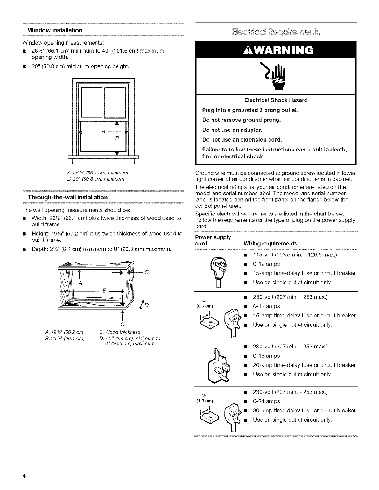
Window installation
Window opening measurements:
• 261/2'' (66.1 cm) minimum to 40" (101.6 cm) maximum
opening width.
• 20" (50.8 cm) minimum opening height.
!
B
h
I J
V
Electrical Shock Hazard
Plug into a grounded 3 prong outlet.
Do not remove ground prong.
Do not use an adapter.
Do not use an extension cord,
Failure to follow these instructions can result in death,
fire, or electrical shock.
A. 26_" (66.1 cm) minimum
B. 20" (50.8 cm) minimum
Through-the-wall installation
The wall opening measurements should be:
• Width: 261/2'' (66.1 cm) plus twice thickness of wood used to
build frame.
• Height: 193/4'' (50.2 cm) plus twice thickness of wood used to
build frame.
• Depth: 21/2'' (6.4 cm) minimum to 8" (20.3 cm) maximum.
c
t
C
A. 19_" (50.2 cm) C. Wood thickness
B.26½"(66.1cm) D.2½" (6.4cm) minimum to
8" (20.8cm) maximum
Ground wire must be connected to ground screw located in lower
right corner of air conditioner when air conditioner is in cabinet.
The electrical ratings for your air conditioner are listed on the
model and serial number label. The model and serial number
label is located behind the front panel on the flange below the
control panel area.
Specific electrical requirements are listed in the chart below.
Follow the requirements for the type of plug on the power supply
cord.
Power supply
cord Wiring requirements
• 115-volt (103.5 min. - 126.5 max.)
(_ • 0-12 amps
1/4"
(0,6 crn) •
• 15-amp time-delay fuse or circuit breaker
• Use on single outlet circuit only.
230-volt (207 min. - 253 max.)
0-12 amps
15-amp time-delay fuse or circuit breaker
Use on single outlet circuit only.
• 230-volt (207 min. - 253 max.)
• 20-amp time-delay fuse or circuit breaker
• 0-16 amps
• Use on single outlet circuit only.
1/2"
(1.3 crn)
_ (_ • 30-amp time-delay fuse or circuit breaker
• 230-volt (207 min. - 253 max.)
• 0-24 amps
Use on single outlet circuit only.
Recommended ground method
This air conditioner must be grounded. This air conditioner is
equipped with a power supply cord having a grounded 3 prong
plug. To minimize possible shock hazard, the cord must be
plugged into a mating, grounded 3 prong outlet, grounded in
accordance with all local codes and ordinances. If a mating outlet
is not available, it is the customer's responsibility to have a
properly grounded 3 prong outlet installed by a qualified electrical
installer.
It is the customer's responsibility:
• To contact a qualified electrical installer.
• To assure that the electrical installation is adequate and in
conformance with National Electrical Code, ANSl/NFPA 70 -
latest edition, and all local codes and ordinances.
Copies of the standards listed may be obtained from:
National Fire Protection Association
One Batterymarch Park
Quincy, MA 02269
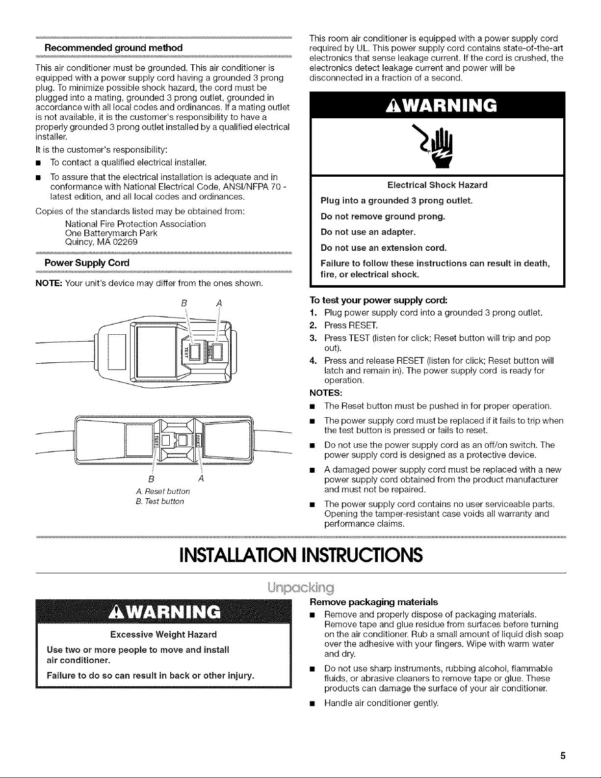
Power Supply Cord
NOTE: Your unit's device may differ from the ones shown.
This room air conditioner is equipped with a power supply cord
required by UL. This power supply cord contains state-of-the-art
electronics that sense leakage current. If the cord is crushed, the
electronics detect leakage current and power will be
disconnected in a fraction of a second.
Electrical Shock Hazard
Plug into a grounded 3 prong outlet.
Do not remove ground prong.
Do not use an adapter.
Do not use an extension cord.
Failure to follow these instructions can result in death,
fire, or electrical shock.
B A
B A
A.Reset button
B. Testbutton
INSTALLATIONINSTRUCTIONS
To test your power supply cord:
1. Plug power supply cord into a grounded 3 prong outlet.
2. Press RESET.
3. Press TEST (listen for click; Reset button will trip and pop
out).
4. Press and release RESET (listen for click; Reset button will
latch and remain in). The power supply cord is ready for
operation.
NOTES:
• The Reset button must be pushed infor proper operation.
• The power supply cord must be replaced if it fails to trip when
the test button is pressed or fails to reset.
• Do not use the power supply cord as an off/on switch. The
power supply cord is designed as a protective device.
• A damaged power supply cord must be replaced with a new
power supply cord obtained from the product manufacturer
and must not be repaired.
• The power supply cord contains no user serviceable parts.
Opening the tamper-resistant case voids all warranty and
performance claims.
Excessive Weight Hazard
Use two or more people to move and install
air conditioner.
Failure to do so can result in back or other injury.
Remove packaging materials
• Remove and properly dispose of packaging materials.
Remove tape and glue residue from surfaces before turning
on the air conditioner. Rub a small amount of liquid dish soap
over the adhesive with your fingers. Wipe with warm water
and dry.
• Do not use sharp instruments, rubbing alcohol, flammable
fluids, or abrasive cleaners to remove tape or glue. These
products can damage the surface of your air conditioner.
• Handle air conditioner gently.
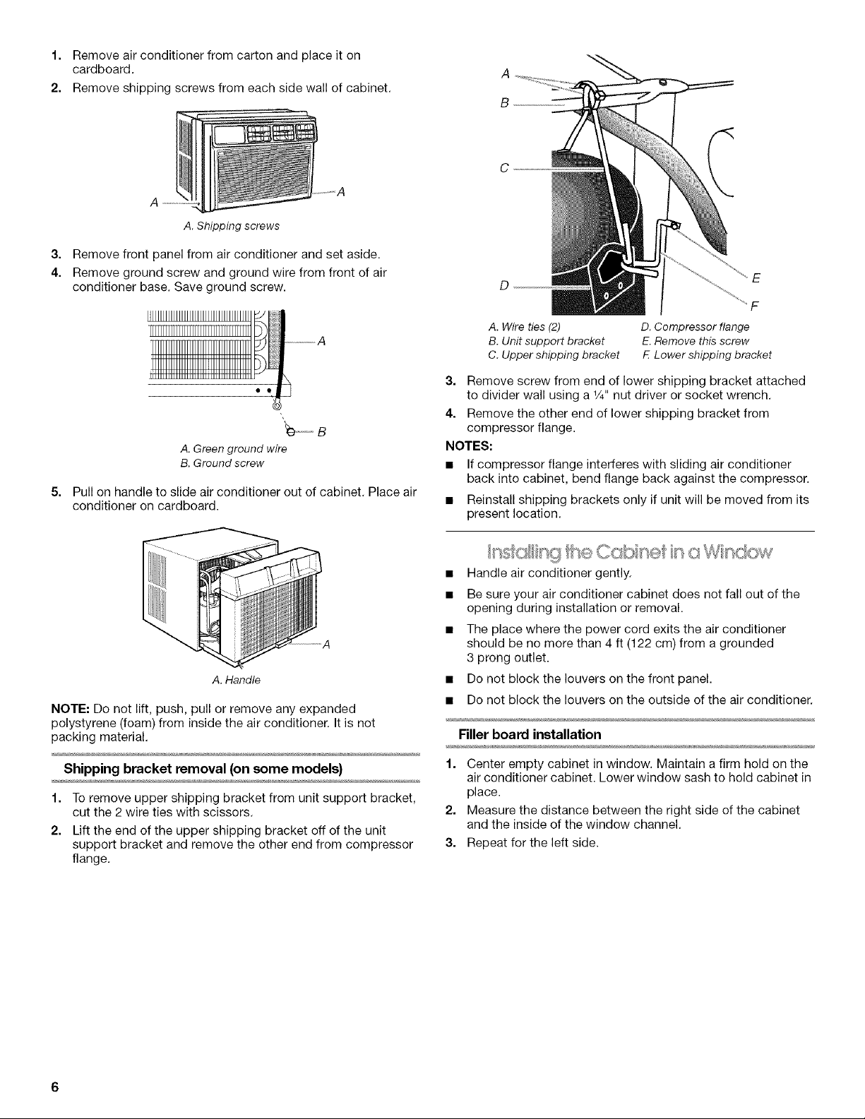
1. Removeairconditionerfromcartonandplaceiton
cardboard.
2. Removeshippingscrewsfromeachsidewallofcabinet.
A. Shipping screws
3. Remove front panel from air conditioner and set aside.
4. Remove ground screw and ground wire from front of air
conditioner base. Save ground screw.
_).......B
A.Green ground wire
B. Groundscrew
5.
Pull on handle to slide air conditioner out of cabinet. Place air
conditioner on cardboard.
A
B
C
F
A. Wire ties (2)
B. Unit support bracket
C. Upper shipping bracket
3. Remove screw from end of lower shipping bracket attached
to divider wall using a 1/4"nut driver or socket wrench.
4. Remove the other end of lower shipping bracket from
compressor flange.
NOTES:
• If compressor flange interferes with sliding air conditioner
back into cabinet, bend flange back against the compressor.
• Reinstall shipping brackets only if unit will be moved from its
present location.
D. Compressor flange
E. Remove this screw
F. Lower shipping bracket
A. Handle
NOTE: Do not lift, push, pull or remove any expanded
polystyrene (foam) from inside the air conditioner. It is not
packing material.
Shipping bracket removal (on some models)
1. To remove upper shipping bracket from unit support bracket,
cut the 2 wire ties with scissors.
2. Lift the end of the upper shipping bracket off of the unit
support bracket and remove the other end from compressor
flange.
• Handle air conditioner gently.
• Be sure your air conditioner cabinet does not fall out of the
opening during installation or removal.
• The place where the power cord exits the air conditioner
should be no more than 4 ft (122 cm) from a grounded
3 prong outlet.
• Do not block the louvers on the front panel.
• Do not block the louvers on the outside of the air conditioner.
Filler board installation
1. Center empty cabinet in window. Maintain a firm hold on the
air conditioner cabinet. Lower window sash to hold cabinet in
place.
2. Measure the distance between the right side of the cabinet
and the inside of the window channel.
3. Repeat for the left side.
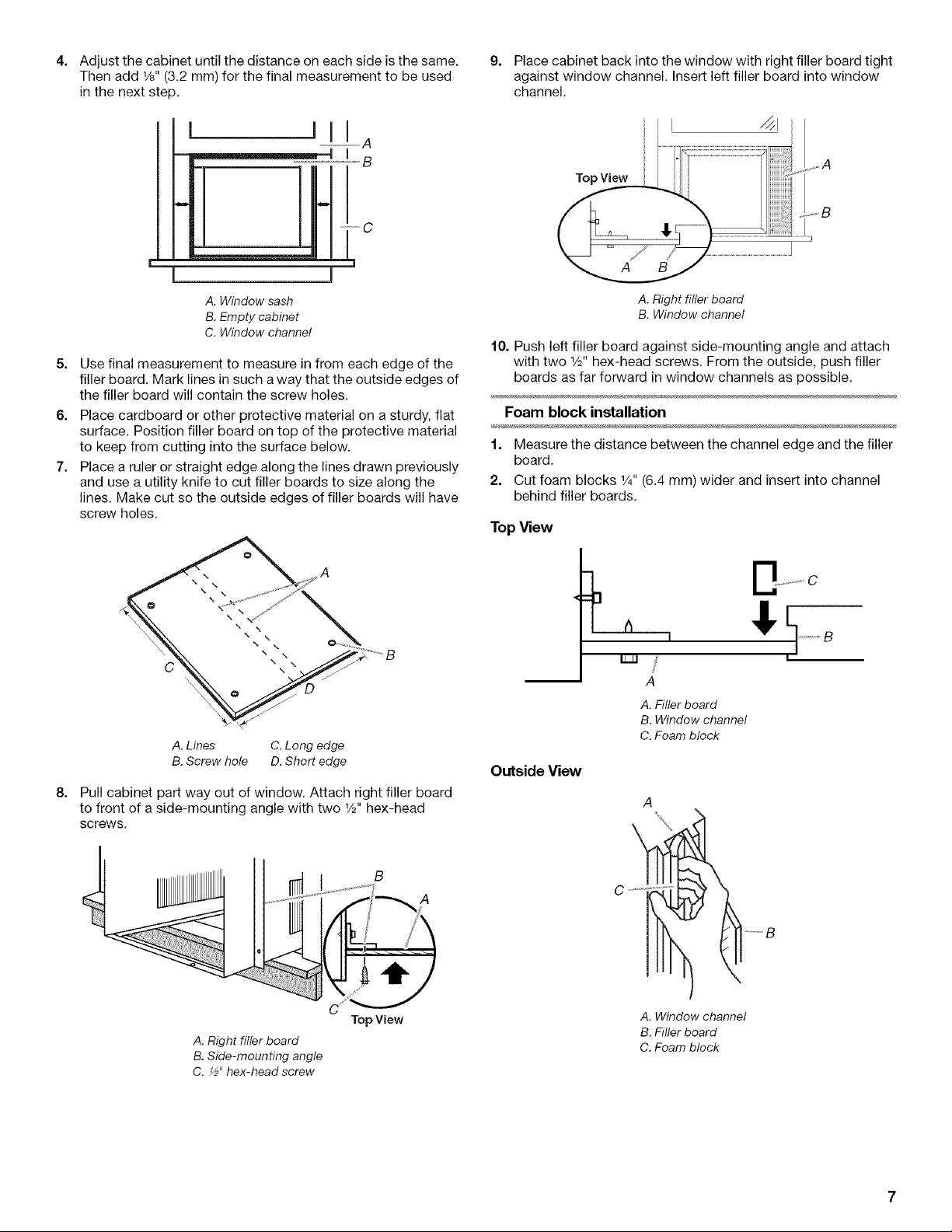
4.
Adjust the cabinet until the distance on each side is the same.
Then add 1/8"(3.2 mm) for the final measurement to be used
in the next step.
l Ilia
L
[
A. Window sash
B. Empty cabinet
C. Window channel
5. Use final measurement to measure in from each edge of the
filler board. Mark lines in such a way that the outside edges of
the filler board will contain the screw holes.
6. Place cardboard or other protective material on a sturdy, flat
surface. Position filler board on top of the protective material
to keep from cutting into the surface below.
7. Place a ruler or straight edge along the lines drawn previously
and use a utility knife to cut filler boards to size along the
lines. Make cut so the outside edges of filler boards will have
screw holes.
I
9.
Place cabinet back into the window with right filler board tight
against window channel. Insert left filler board into window
channel.
Top View
A. Right filler board
B. Window channel
10. Push left filler board against side-mounting angle and attach
with two 1/2"hex-head screws. From the outside, push filler
boards as far forward in window channels as possible.
Foam block installation
1. Measure the distance between the channel edge and the filler
board.
2. Cut foam blocks 1/4"(6.4 mm) wider and insert into channel
behind filler boards.
TopView
A. Lines C. Long edge
B. Screw hole D. Short edge
8.
Pull cabinet part way out of window. Attach right filler board
to front of a side-mounting angle with two 1/2"hex-head
screws.
B
C ¸
TopView
A. Right filler board
B. Side-mounting angle
C. ½" hex-head screw
b
,,/
A
A. Filler board
B. Window channel
C. Foam block
Outside View
A
A
C .......
......... B
A. Window channel
B. Filler board
C. Foam block
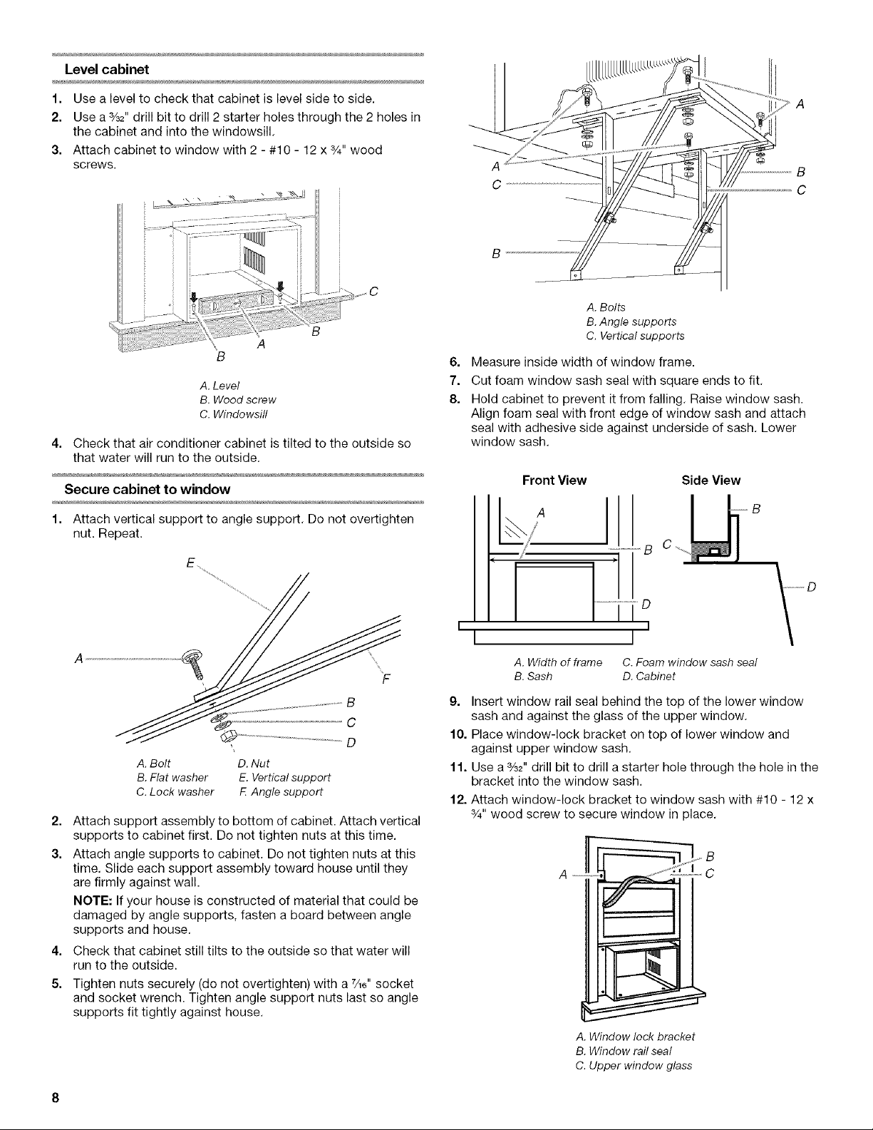
Level cabinet
1. Use a level to check that cabinet is level side to side.
2. Use a %2" drill bit to drill 2 starter holes throuc hthe 2 holes in
the cabinet and into the windowsill.
3. Attach cabinet to window with 2 - #10 - 12 x %" wood
screws.
B
A
B
A. Level
B. Wood screw
C. Windowsill
4. Check that air conditioner cabinet is tilted to the outside so
that water will run to the outside.
Secure cabinet to window
A
C
A. Bolts
B.Angle supports
C. Verticalsupports
6=
Measure inside width of window frame.
7.
Cut foam window sash seal with square ends to fit.
8.
Hold cabinet to prevent it from falling. Raise window sash.
Align foam seal with front edge of window sash and attach
seal with adhesive side against underside of sash. Lower
window sash.
Front View Side View
1. Attach vertical support to angle support. Do not overtighten
nut. Repeat.
E_
.................... B
A. Bolt D. Nut
B. Fiat washer E. Vertical support
C. Lock washer F. Angle support
2=
Attach support assembly to bottom of cabinet. Attach vertical
supports to cabinet first. Do not tighten nuts at this time.
3.
Attach angle supports to cabinet. Do not tighten nuts at this
time. Slide each support assembly toward house until they
are firmly against wall.
NOTE: If your house is constructed of material that could be
damaged by angle supports, fasten a board between angle
supports and house.
4. Check that cabinet still tilts to the outside so that water will
run to the outside.
5. Tighten nuts securely (do not overtighten) with a 7_6"socket
and socket wrench. Tighten angle support nuts last so angle
supports fit tightly against house.
................... B
...... i ............... b
I
I
[
A. Width of frame C. Foam window sash seal
B. Sash D. Cabinet
9. Insert window rail seal behind the top of the lower window
sash and against the glass of the upper window.
10. Place window-lock bracket on top of lower window and
against upper window sash.
11. Use a %2" drill bit to drill a starter hole through the hole in the
bracket into the window sash.
12. Attach window-lock bracket to window sash with #10 - 12 x
3/4"wood screw to secure window in place.
A C
A. Window lock bracket
B. Window rail seal
C. Upper window glass
I
J
_B
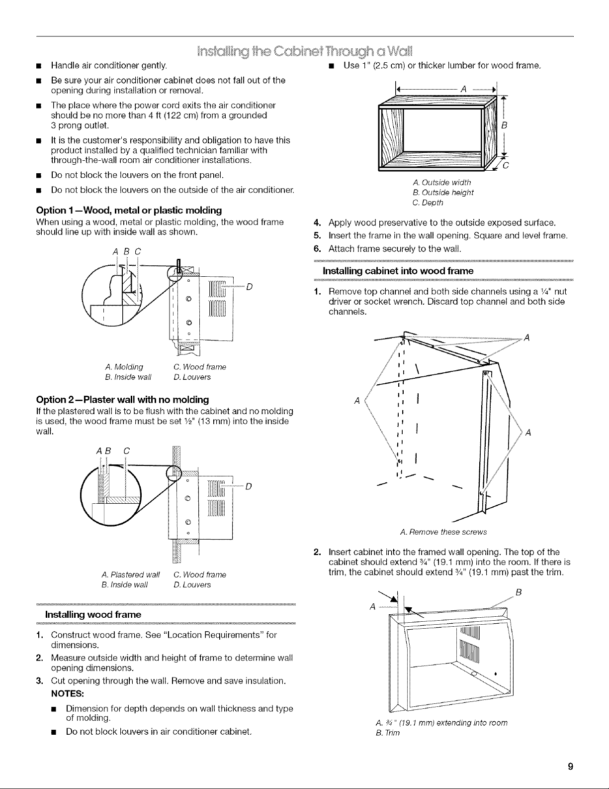
Handle air conditioner gently. • Use 1" (2.5 cm) or thicker lumber for wood frame.
Be sure your air conditioner cabinet does not fall out of the
opening during installation or removal.
The place where the power cord exits the air conditioner
should be no more than 4 ft (122 cm) from a grounded
3 prong outlet.
It is the customer's responsibility and obligation to have this
product installed by a qualified technician familiar with
through-the-wall room air conditioner installations.
Do not block the louvers on the front panel.
Do not block the louvers on the outside of the air conditioner.
Option 1--Wood, metal or plastic molding
When using a wood, metal or plastic molding, the wood frame
should line up with inside wall as shown.
ABC
4. Apply wood preservative to the outside exposed surface.
5. Insert the frame in the wall opening. Square and level frame.
6. Attach frame securely to the wall.
Installing cabinet into wood frame
A. Outside width
B. Outside height
C. Depth
.
B
l
_ ..... D
A. Molding
B. Inside wall
Option 2--Plaster wall with no molding
If the plastered wall is to be flush with the cabinet and no molding
is used, the wood frame must be set Y2" (13 ram) into the inside
wall.
AB C
i i
A. Plastered wall C. Wood frame
B. Inside wall D. Louvers
C. Wood frame
D.Louvers
1. Remove top channel and both side channels using a _/4"nut
driver or socket wrench. Discard top channel and both side
channels.
A. Remove these screws
2=
Insert cabinet into the framed wall opening. The top of the
cabinet should extend 3/4"(19.1 mm) into the room. Ifthere is
trim, the cabinet should extend 3/4"(19.1 mm) past the trim.
Installing wood frame
1. Construct wood frame. See "Location Requirements" for
dimensions.
2. Measure outside width and height of frame to determine wall
opening dimensions.
3. Cut opening through the wall. Remove and save insulation.
NOTES:
• Dimension for depth depends on wall thickness and type
of molding.
• Do not block louvers in air conditioner cabinet.
A
A. _ " (19.1 mm) extending into room
B. Trim
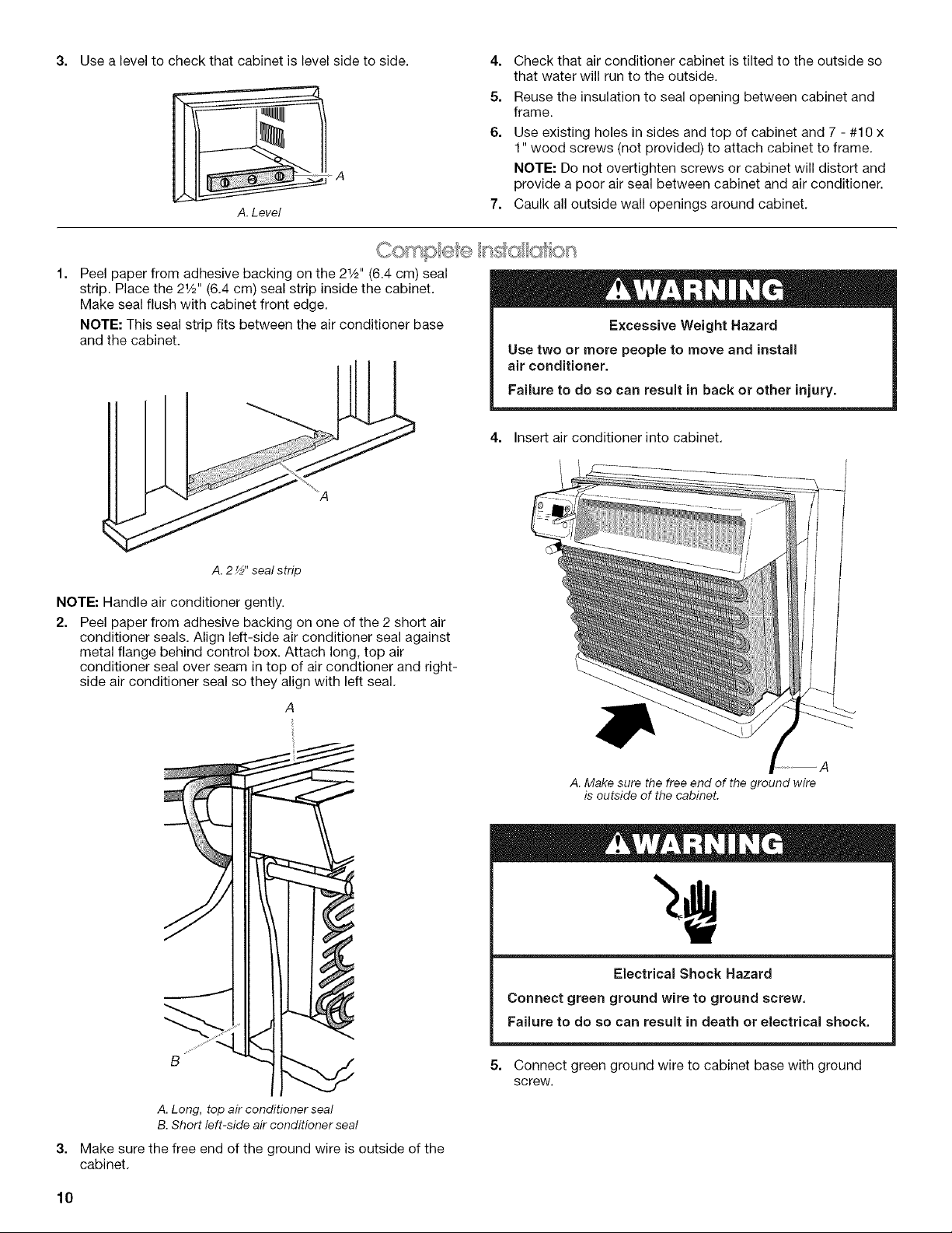
3= Use a level to check that cabinet is level side to side.
A.Level
Peel paper from adhesive backing on the 2W' (6.4 cm) seal
strip. Place the 2W' (6.4 cm) seal strip inside the cabinet.
Make seal flush with cabinet front edge.
NOTE: This seal strip fits between the air conditioner base
and the cabinet.
4.
Check that air conditioner cabinet is tilted to the outside so
that water will run to the outside.
5.
Reuse the insulation to seal opening between cabinet and
frame.
6.
Use existing holes in sides and top of cabinet and 7 - #10 x
1" wood screws (not provided) to attach cabinet to frame.
NOTE: Do not overtighten screws or cabinet will distort and
provide a poor air seal between cabinet and air conditioner.
7.
Caulk all outside wall openings around cabinet,
Excessive Weight Hazard
Use two or more people to move and install
air conditioner.
Failure to do so can result in back or other injury.
4. Insert air conditioner into cabinet,
I
A. 2_" seal strip
NOTE: Handle air conditioner gently.
2. Peel paper from adhesive backing on one of the 2 short air
conditioner seals. Align left-side air conditioner seal against
metal flange behind control box. Attach long, top air
conditioner seal over seam in top of air condtioner and right-
side air conditioner seal so they align with left seal.
A. Make sure the free end of the ground wire
is outside of the cabinet.
B
A. Long, top air conditioner seal
B. Short left-side air conditioner seal
3=
Make sure the free end of the ground wire is outside of the
cabinet,
10
Electrical Shock Hazard
Connect green ground wire to ground screw,
Failure to do so can result in death or electrical shock.
5. Connect green ground wire to cabinet base with ground
screw.
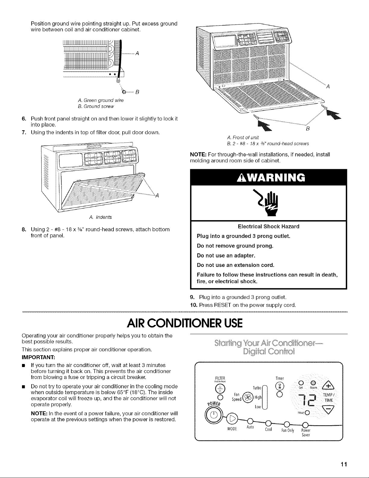
Position ground wire pointing straight up. Put excess ground
wire between coil and air conditioner cabinet.
...........B
A. Green ground wire
B. Ground screw
6. Push front panel straight on and then lower it slightlyto lock it
into place.
7. Using the indents in top of filter door, pull door down.
B
A.Front of unit
B.2 - #8- 18x _" round-headscrews
NOTE: For through-the-wall installations, if needed, install
molding around room side of cabinet.
A. Indents
8,
Using 2 - #8 - 18 x %" round-head screws, attach bottom
front of panel.
AIRCONDITIONERUSE
Operating your air conditioner properly helps you to obtain the
best possible results.
This section explains proper air conditioner operation.
IMPORTANT:
• If you turn the air conditioner off, wait at least 3 minutes
before turning it back on. This prevents the air conditioner
from blowing a fuse or tripping a circuit breaker.
Do not try to operate your air conditioner in the cooling mode
when outside temperature is below 65°F (18°C). The inside
evaporator coil will freeze up, and the air conditioner will not
operate properly.
NOTE: In the event of a power failure, your air conditioner will
operate at the previous settings when the power is restored.
Electrical Shock Hazard
Plug into a grounded 3 prong outlet.
Do not remove ground prong.
Do not use an adapter.
Do not use an extension cord,
Failure to follow these instructions can result in death,
fire, or electrical shock.
g. Plug into a grounded 3 prong outlet.
10. Press RESET on the power supply cord.
© g Co ' fro
FILTER Timer
......... 0 @
Fan _ I I 0 ------ TEMPI
MODE
Auto ."%
Lctoo FanOnly Power
Saver
J
11
 Loading...