

Whirlpool ACQ128PT1, ACQ128PT0, ACQ122PT1, ACQ122PT0, ACM124PT1 Owner’s Manual
...
AIRCONDITIONER
For questions about features, operation/performance, parts,
accessories or service, call: 1-800-253-1301 in the U.S.A.
ACONDICIONADOR
Si tiene preguntas respeeto alas caracterfsticas, funcionamiento,
rendimiento, piezas, accesorios o servicio tecnico,
Ilame al: 1-800-253-1301 en los EE. UU.
Table of Contents/indice ..................................... 2
66121559A
TABLEOF CONTENTS
AIR CONDITIONER SAFETY ......................................................... 2
INSTALLATION REQUIREMENTS ................................................ 3
Tools and Parts ............................................................................ 3
Location Requirements ................................................................ 3
Electrical Requirements ............................................................... 4
INSTALLATION INSTRUCTIONS .................................................. 5
Unpack the Air Conditioner .......................................................... 5
Window Installation (on some models) ........................................ 6
Through-the-Wall Cabinet Installation ......................................... 8
Complete Installation ................................................................. 10
AIR CONDITIONER USE.............................................................. 11
Starting Your Air Conditioner-- Digital Control .......................... 11
Using the Remote Control ......................................................... 12
[NDICE
SEGURIDAD DEL ACONDICIONADOR DE AIRE ...................... 18
REQUISITOS DE INSTALACION ................................................. 18
Herramientas y piezas ................................................................ 18
Requisitos de ubicaci6n ............................................................. 19
Requisites electricos .................................................................. 20
INSTRUCCIONES DE INSTALACION ......................................... 21
Desempaque el acondicionador de aire.................................... 21
Instalaci6n en una ventana (en algunos modelos) .................... 22
Instalaci6n a traves de la pared ................................................. 24
Complete la instalaci6n .............................................................. 26
USO DE SU ACONDICIONADOR DE AIRE ................................ 27
C6mo poner en marcha su acondicionador de aire--
Control digital ............................................................................. 27
C6mo usar el control remoto ..................................................... 29
Starting Your Air Conditioner--Rotary Control--
Cool Only Models ....................................................................... 13
Starting Your Air Conditioner--Rotary Control--
Heat/Cool Models ...................................................................... 14
Changing Air Direction ............................................................... 15
Normal Sounds ........................................................................... 15
AIR CONDITIONER CARE ........................................................... 15
Cleaning the Air Filter ................................................................. 15
Cleaning the Front Panel ............................................................ 15
Repairing Paint Damage ............................................................ 15
Annual Maintenance ................................................................... 15
TROUBLESHOOTING .................................................................. 16
ASSISTANCE OR SERVICE ......................................................... 17
Accessories ................................................................................ 17
C6mo poner en marcha su acondicionador de aire--
Control rotativo--Modelos con s61o aire frio ............................. 30
C6mo poner en marcha su acondicionador de aire--
Control rotativo--Modelos con aire caliente/frio ....................... 31
C6mo cambiar la direcci6n del aire ........................................... 31
Sonidos normales ....................................................................... 32
COMO CUIDAR SU ACONDICIONADOR DE AIRE ................... 32
Limpieza del filtro de aire ........................................................... 32
Limpieza del panel delantero ..................................................... 32
Reparaci6n de la pintura da_ada ............................................... 32
Mantenimiento anual .................................................................. 32
SOLUCION DE PROBLEMAS ...................................................... 33
AYUDA O SERVICIO TI_CNICO ................................................... 34
Accesorios .................................................................................. 35
AIR CONDITIONERSAFETY
Your safety and the safety of others are very important.
We have provided many important safety messages in this manual and on your appliance. Always read and obey all safety
messages.
This is the safety alert symbol.
This symbol alerts you to potential hazards that can kill or hurt you and others.
All safety messages will follow the safety alert symbol and either the word "DANGER" or "WARNING."
These words mean:
You can be killed or seriously injured if you don't immediately
follow instructions.
You can be killed or seriously injured if you don't follow
instructions.
All safety messages will tell you what the potential hazard is, tell you how to reduce the chance of injury, and tell you what can
happen if the instructions are not followed.
IMPORTANT SAFETY INSTRUCTIONS
WARN ING: To reduce the risk of fire, electrical shock or injury when using your air conditioner, follow these basic precautions:
• Plug into a grounded 3 prong outlet.
• Do not use an extension cord.
• Do not remove ground prong.
• Do not use an adapter.
SAVE TH ESE INSTRUCTIONS
INSTALLATIONREQUIREMENTS
Gather the required tools and parts before starting installation.
Read and follow the instructions provided with any tools listed
here.
Tools Needed
• Flat-blade and Phillips • Tape measure
screwdrivers
• Level
Through-the-Wall Installation:
In addition to the tools listed above, the following tools are
needed for through-the-wall installation.
• Saw • 1" (2.5 cm) or thicker
• Wood preservative
• Caulk • #10 x 1" wood screws (7)
• Drill and %2" or smaller bit
lumber
• Unplug air conditioner before servicing.
• Use two or more people to move and install air conditioner.
IMPORTANT: Observe all governing codes and ordinances.
Check the location where air conditioner will be installed. Proper
installation is your responsibility. Make sure you have everything
necessary for correct installation.
The location should provide:
• Grounded electrical outlet within 4 ft (122 cm) of where the
power cord exits the air conditioner.
NOTE: Do not use an extension cord.
• Free movement of air in room to be cooled.
• A large enough opening for the air conditioner.
• Adequate wall support for weight of air conditioner. Air
conditioner weighs between 88 and 100 Ibs (40 to 45 kg).
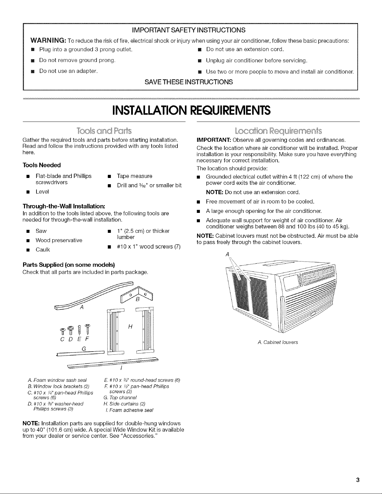
NOTE: Cabinet louvers must not be obstructed. Air must be able
to pass freely through the cabinet louvers.
A
Parts Supplied (on some models)
Check that all parts are included in parts package.
A
H
CDEF
G
A.Foam window sash seal
B. Window lock brackets (2)
C. #10x _" pan-head Phillips
screws (6)
D. #10x %" washer-head
Phillips screws (3)
NOTE: Installation parts are supplied for double-hung windows
up to 40" (101.6 cm) wide. A special Wide Window Kit is available
from your dealer or service center. See "Accessories."
E.#10 x %" round-head screws (6)
F #10 x _" pan-head Phillips
screws (3)
G. Top channel
H. Side curtains (2)
I. Foam adhesive seal
A. Cabinet louvers
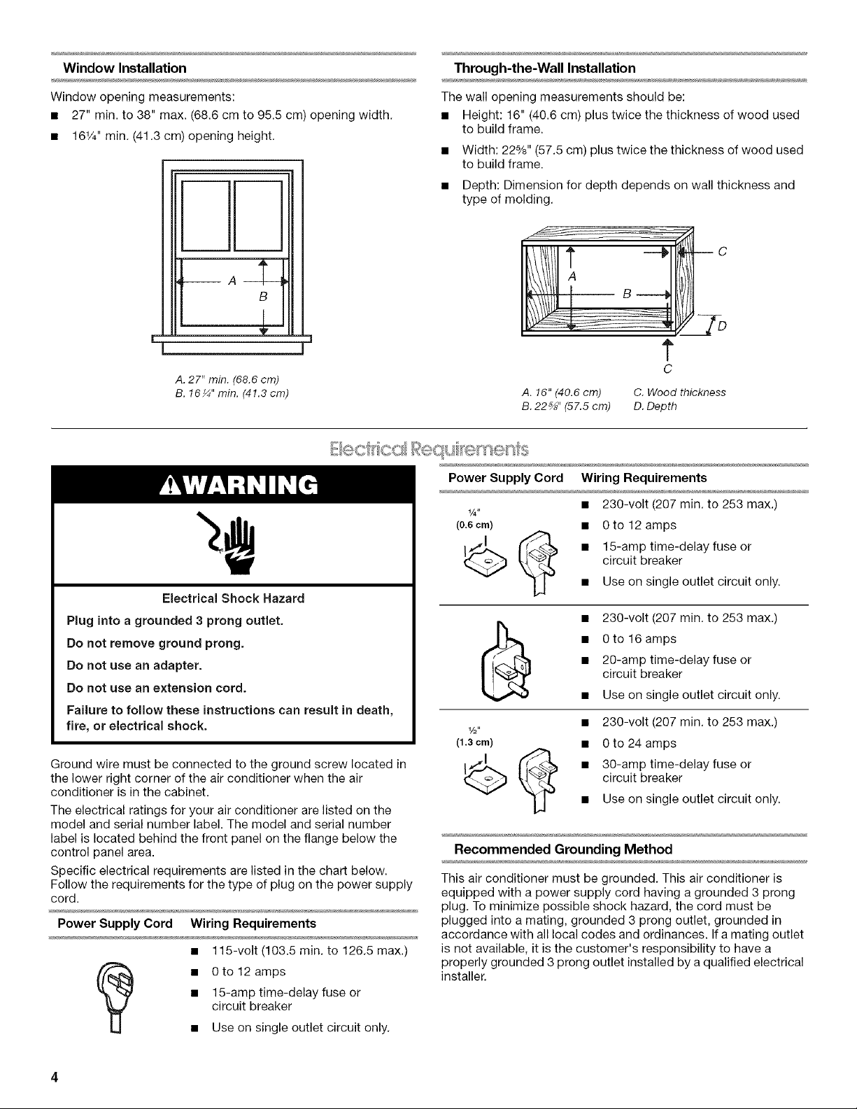
Window Installation
Through-the-Wall Installation
Window opening measurements:
• 27" min. to 38" max. (68.6 cm to 95.5 cm) opening width.
• 161/4'' min. (41.3 cm) opening height.
t
B
E
!
A. 27" min. (68.6 cm)
B. 16_" min. (41.3 cm)
J
The wall opening measurements should be:
• Height: 16" (40.6 cm) plus twice the thickness of wood used
to build frame.
• Width: 22%" (57.5 cm) plus twice the thickness of wood used
to build frame.
• Depth: Dimension for depth depends on wall thickness and
type of molding.
B c
t
C
A. 16" (40.6 cm) C. Wood thickness
B. 22_" (57.5 cm) D. Depth
Power Supply Cord Wiring Requirements
Electrical Shock Hazard
Plug into a grounded 3 prong outlet.
Do not remove ground prong.
Do not use an adapter.
Do not use an extension cord.
Failure to follow these instructions can result in death,
fire, or electrical shock.
Ground wire must be connected to the ground screw located in
the lower right corner of the air conditioner when the air
conditioner is in the cabinet.
The electrical ratings for your air conditioner are listed on the
model and serial number label. The model and serial number
label is located behind the front panel on the flange below the
control panel area.
Specific electrical requirements are listed in the chart below.
Follow the requirements for the type of plug on the power supply
cord.
Power Supply Cord Wiring Requirements
• 115-volt (103.5 min. to 126.5 max.)
• 15-amp time-delay fuse or
circuit breaker
• 0 to 12 amps
• Use on single outlet circuit only.
• 230-volt (207 min. to 253 max.)
(0.6 cm) •
1/2"
(1.3cm) • 0to24amps
_ _ • 30-amp time-delay fuse or
0 to 12 amps
15-amp time-delay fuse or
circuit breaker
Use on single outlet circuit only.
• 230-volt (207 min. to 253 max.)
• 20-amp time-delay fuse or
circuit breaker
• 0 to 16 amps
• Use on single outlet circuit only.
• 230-volt (207 min. to 253 max.)
circuit breaker
• Use on single outlet circuit only.
Recommended Grounding Method
This air conditioner must be grounded. This air conditioner is
equipped with a power supply cord having a grounded 3 prong
plug. To minimize possible shock hazard, the cord must be
plugged into a mating, grounded 3 prong outlet, grounded in
accordance with all local codes and ordinances. If a mating outlet
is not available, it is the customer's responsibility to have a
properly grounded 3 prong outlet installed by a qualified electrical
installer.
Itisthecustomer'sresponsibility:
• To contact a qualified electrical installer.
• To assure that the electrical installation is adequate and in
conformance with National Electrical Code, ANSl/NFPA 70 -
latest edition, and all local codes and ordinances.
Copies of the standards listed may be obtained from:
National Fire Protection Association
One Batterymarch Park
Quincy, MA 02269
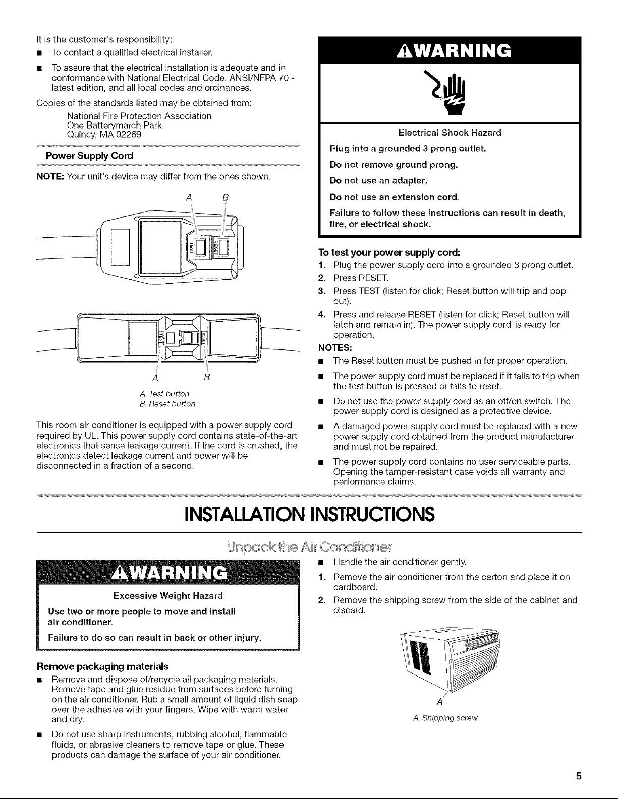
Power Supply Cord
NOTE: Your unit's device may differ from the ones shown.
A B
A B
A. Test button
B. Reset button
This room air conditioner is equipped with a power supply cord
required by UL. This power supply cord contains state-of-the-art
electronics that sense leakage current. If the cord is crushed, the
electronics detect leakage current and power will be
disconnected in a fraction of a second.
Electrical Shock Hazard
Plug into a grounded 3 prong outlet.
Do not remove ground prong.
Do not use an adapter.
Do not use an extension cord.
Failure to follow these instructions can result in death,
fire, or electrical shock.
To test your power supply cord:
1. Plug the power supply cord into a grounded 3 prong outlet.
2. Press RESET.
3. Press TEST (listen for click; Reset button will trip and pop
out).
4. Press and release RESET (listen for click; Reset button will
latch and remain in). The power supply cord is ready for
operation.
NOTES:
• The Reset button must be pushed infor proper operation.
• The power supply cord must be replaced if it fails to trip when
the test button is pressed or fails to reset.
• Do not use the power supply cord as an off/on switch. The
power supply cord is designed as a protective device.
• A damaged power supply cord must be replaced with a new
power supply cord obtained from the product manufacturer
and must not be repaired.
• The power supply cord contains no user serviceable parts.
Opening the tamper-resistant case voids all warranty and
performance claims.
INSTALLATIONINSTRUCTIONS
Excessive Weight Hazard
Use two or more people to move and install
air conditioner.
Failure to do so can result in hack or other injury.
Remove packaging materials
• Remove and dispose of/recycle all packaging materials.
Remove tape and glue residue from surfaces before turning
on the air conditioner. Rub a small amount of liquid dish soap
over the adhesive with your fingers. Wipe with warm water
and dry.
• Do not use sharp instruments, rubbing alcohol, flammable
fluids, or abrasive cleaners to remove tape or glue. These
products can damage the surface of your air conditioner.
Handle the air conditioner gently.
1.
Remove the air conditioner from the carton and place it on
cardboard.
2=
Remove the shipping screw from the side of the cabinet and
discard.
A
A. Shipping screw
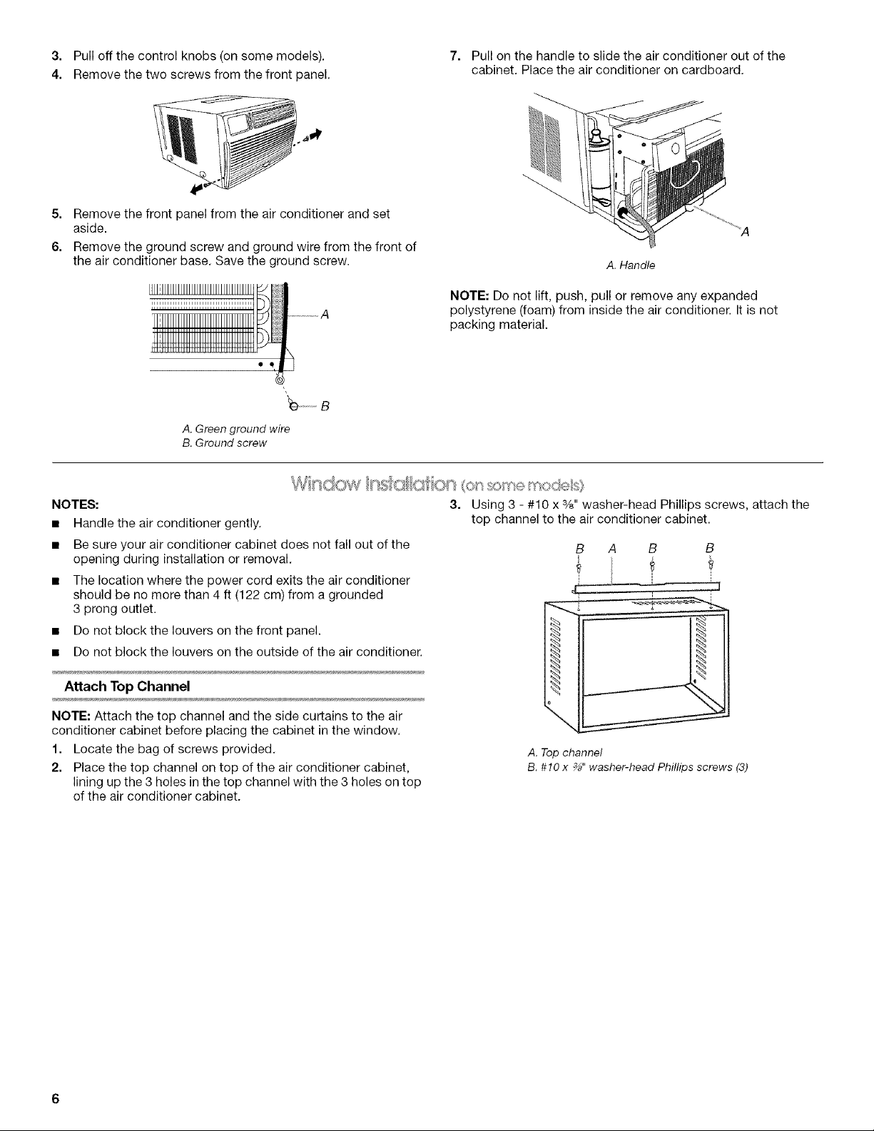
3. Pulloffthecontrolknobs(onsomemodels).
4. Removethetwoscrewsfromthefrontpanel.
5. Remove the front panel from the air conditioner and set
aside.
6. Remove the ground screw and ground wire from the front of
the air conditioner base. Save the ground screw.
'_ ..............B
A. Green ground wire
B. Ground screw
7. Pull on the handle to slide the air conditioner out of the
cabinet. Place the air conditioner on cardboard.
A. Handle
NOTE: Do not lift, push, pull or remove any expanded
polystyrene (foam) from inside the air conditioner. It is not
packing material.
NOTES:
• Handle the air conditioner gently.
Be sure your air conditioner cabinet does not fall out of the
opening during installation or removal,
The location where the power cord exits the air conditioner
should be no more than 4 ft (122 cm) from a grounded
3 prong outlet.
Do not block the louvers on the front panel.
Do not block the louvers on the outside of the air conditioner.
Attach Top Channel
NOTE: Attach the top channel and the side curtains to the air
conditioner cabinet before placing the cabinet in the window.
1. Locate the bag of screws provided.
2. Place the top channel on top of the air conditioner cabinet,
lining up the 3 holes in the top channel with the 3 holes on top
of the air conditioner cabinet.
3. Using 3 - #10 x %" washer-head Phillips screws, attach the
top channel to the air conditioner cabinet.
B A B B
?
A. Top channel
B. #10 x _" washer-head Phillips screws (3)
Attach Side Curtains
1. Locate the bag of screws provided.
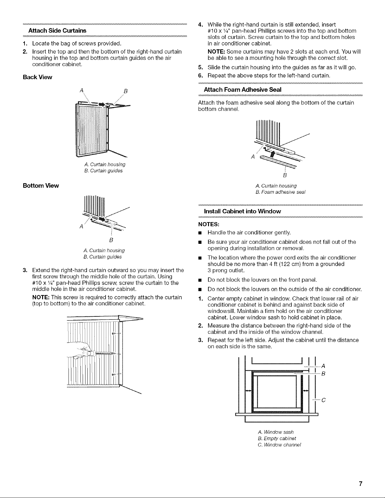
2. Insert the top and then the bottom of the right-hand curtain
housing in the top and bottom curtain guides on the air
conditioner cabinet.
Back View
4. While the right-hand curtain is still extended, insert
#10 x 1/4"pan-head Phillips screws into the top and bottom
slots of curtain. Screw curtain to the top and bottom holes
in air conditioner cabinet.
NOTE: Some curtains may have 2 slots at each end. You will
be able to see a mounting hole through the correct slot.
5. Slide the curtain housing into the guides as far as it will go.
6. Repeat the above steps for the left-hand curtain.
A B
A. Curtain housing
B. Curtain guides
Bottom View
A
B
A. Curtain housing
B. Curtain guides
3.
Extend the right-hand curtain outward so you may insert the
first screw through the middle hole of the curtain. Using
#10 x 1/4"pan-head Phillips screw, screw the curtain to the
middle hole in the air conditioner cabinet.
NOTE: This screw is required to correctly attach the curtain
(top to bottom) to the air conditioner cabinet.
Attach Foam Adhesive Seal
Attach the foam adhesive seal along the bottom of the curtain
bottom channel.
A
A. Curtain housing
B. Foam adhesive seal
Install Cabinet intoWindow
NOTES:
• Handle the air conditioner gently.
• Be sure your air conditioner cabinet does not fall out of the
opening during installation or removal.
• The location where the power cord exits the air conditioner
should be no more than 4 ft (122 cm) from a grounded
3 prong outlet.
• Do not block the louvers on the front panel.
• Do not block the louvers on the outside of the air conditioner.
1. Center empty cabinet in window. Check that lower rail of air
conditioner cabinet is behind and against back side of
windowsill. Maintain a firm hold on the air conditioner
cabinet. Lower window sash to hold cabinet in place.
2. Measure the distance between the right-hand side of the
cabinet and the inside of the window channel.
3. Repeat for the left side. Adjust the cabinet until the distance
on each side is the same.
A. Window sash
B. Empty cabinet
C. Window channel
I
B
J
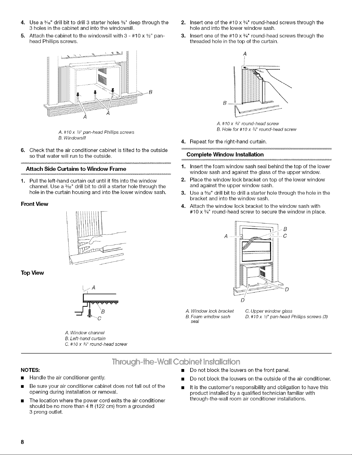
4.
Use a 3/16"drill bit to drill 3 starter holes %" deep through the
3 holes in the cabinet and into the windowsill.
5.
Attach the cabinet to the windowsill with 3 - #10 x 1/2"pan-
head Phillips screws.
A
A. #10 x _" pan-head Phillips screws
B. Windowsill
6. Check that the air conditioner cabinet is tilted to the outside
so that water will run to the outside.
2.
Insert one of the #10 x 3/4"round-head screws through the
hole and into the lower window sash.
3.
Insert one of the #10 x 3/4"round-head screws through the
threaded hole in the top of the curtain.
A. #10 x _" round-head screw
B. Hole for #10 x _" round-head screw
4. Repeat for the right-hand curtain.
Complete Window Installation
Attach Side Curtains to Window Frame
1. Pull the left-hand curtain out until it fits into the window
channel. Use a %2" drill bit to drill a starter hole through the
hole in the curtain housing and into the lower window sash.
Front View
TopView
[i A
_j--Jlv v vv v v
........._B
A. Window channel
B. Left-hand curtain
C. #10 x _" round-head screw
1. Insert the foam window sash seal behind the top of the lower
window sash and against the glass of the upper window.
2. Place the window lock bracket on top of the lower window
and against the upper window sash.
3. Use a 3/32"drill bit to drill a starter hole through the hole in the
bracket and into the window sash.
4. Attach the window lock bracket to the window sash with
#10 x 3/4"round-head screw to secure the window in place.
B
A C
D
A. Window lock bracket
B. Foam window sash
seal
C. Upper window glass
D. #10 x ½" pan-head Phillips screws (3)
NOTES:
• Handle the air conditioner gently.
• Be sure your air conditioner cabinet does not fall out of the
opening during installation or removal.
• The location where the power cord exits the air conditioner
should be no more than 4 ft (122 cm) from a grounded
3 prong outlet.
• Do not block the louvers on the front panel.
• Do not block the louvers on the outside of the air conditioner.
• It is the customer's responsibility and obligation to have this
product installed by a qualified technician familiar with
through-the-wall room air conditioner installations.

Option1--Wood,metalorplasticmolding
Whenusingwood,metalorplasticmolding,thewoodframe
shouldlineupwiththeinsidewallasshown.
ABC
II -!
• Use 1" (2.5 cm) or thicker lumber for the wood frame.
A. Outside width
B. Outside height
C. Depth
A. Molding C. Wood frame
B. Inside wall D.Louvers
Option 2--Plastered wall with no molding
If the plastered wall is to be flush with the cabinet and no molding
is used, the wood frame must be set 1/2"(13 ram) into the inside
wall.
AB C
A. Plastered wall C. Wood frame
B. Inside wall D. Louvers
Install Wood Frame
1. Construct the wood frame. See "Location Requirements" for
dimensions.
2. Measure the outside width and height of the frame to
determine the wall opening dimensions.
3. Cut the opening through the wall. Remove and save the
insulation.
NOTES:
• Dimension for depth depends on the wall thickness and
the type of molding.
• Do not block the louvers in the air conditioner cabinet.
4. Apply the wood preservative to the outside exposed surface.
5. Insert the frame in the wall opening. Square and level the
frame.
6. Attach the frame securely to the wall.
Install Cabinet into Wood Frame
1. Insert the cabinet into the framed wall opening.
A. Trim
2. Use a level to check that the cabinet is level side to side.
A. Level
3. Check that the air conditioner cabinet is tilted to the outside
so that water will run to the outside.
Complete Through-the-Wall Installation
1.
Reuse the insulation to seal the opening between the cabinet
and the frame.
2.
Use the existing holes and 6 - #10 x 1" wood screws (not
provided) to attach the cabinet to the frame.
NOTE: Do not overtighten the screws or the cabinet will
distort and provide a poor air seal between the cabinet and
the air conditioner.
3. Caulk all outside wall openings around the cabinet.
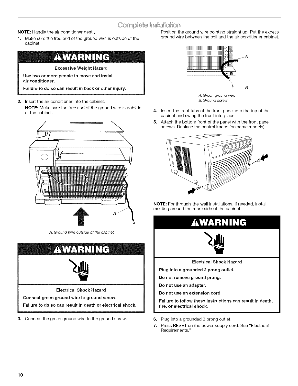
NOTE: Handle the air conditioner gently. Position the ground wire pointing straight up. Put the excess
1. Make sure the free end of the ground wire is outside of the ground wire between the coil and the air conditioner cabinet.
cabinet.
Excessive Weight Hazard
Use two or more people to move and install
air conditioner.
Failure to do so can result in back or other injury.
A. Green ground wire
2. Insert the air conditioner into the cabinet.
NOTE: Make sure the free end of the ground wire is outside
of the cabinet.
4. Insert the front tabs of the front panel into the top of the
cabinet and swing the front into place.
B. Ground screw
5. Attach the bottom front of the panel with the front panel
screws. Replace the control knobs (on some models).
t A
A, Ground wire outside of the cabinet
Electrical Shock Hazard
Connect green ground wire to ground screw.
Failure to do so can result in death or electrical shock.
3. Connect the green ground wire to the ground screw.
NOTE: For through-the-wall installations, if needed, install
molding around the room side of the cabinet.
Electrical Shock Hazard
Plug into a grounded 3 prong outlet.
Do not remove ground prong.
Do not use an adapter.
Do not use an extension cord.
Failure to follow these instructions can result in death,
fire, or electrical shock.
6. Plug into a grounded 3 prong outlet.
7. Press RESET on the power supply cord. See "Electrical
Requirements."
10
AIR CONDITIONERUSE
Operating your air conditioner properly helps you to obtain the
best possible results.
This section explains proper air conditioner operation.
IMPORTANT:
• If you turn off the air conditioner, wait at least 3 minutes
before turning it back on. This prevents the air conditioner
from blowing a fuse or tripping a circuit breaker.
f
0 Turbo0
TIMER FANSPEED Low 0
_ Auto 0
MODE Cool FanOnly PowerSaver
TEMP • Power Saver--Fan runs only when cooling is needed. You
O_ circulated as often. Use Power Saver when you are
%,_/ o,FILTER........ asleep or away from home.
-% 2. Choose Cool, Fan Only or Power Saver.
J
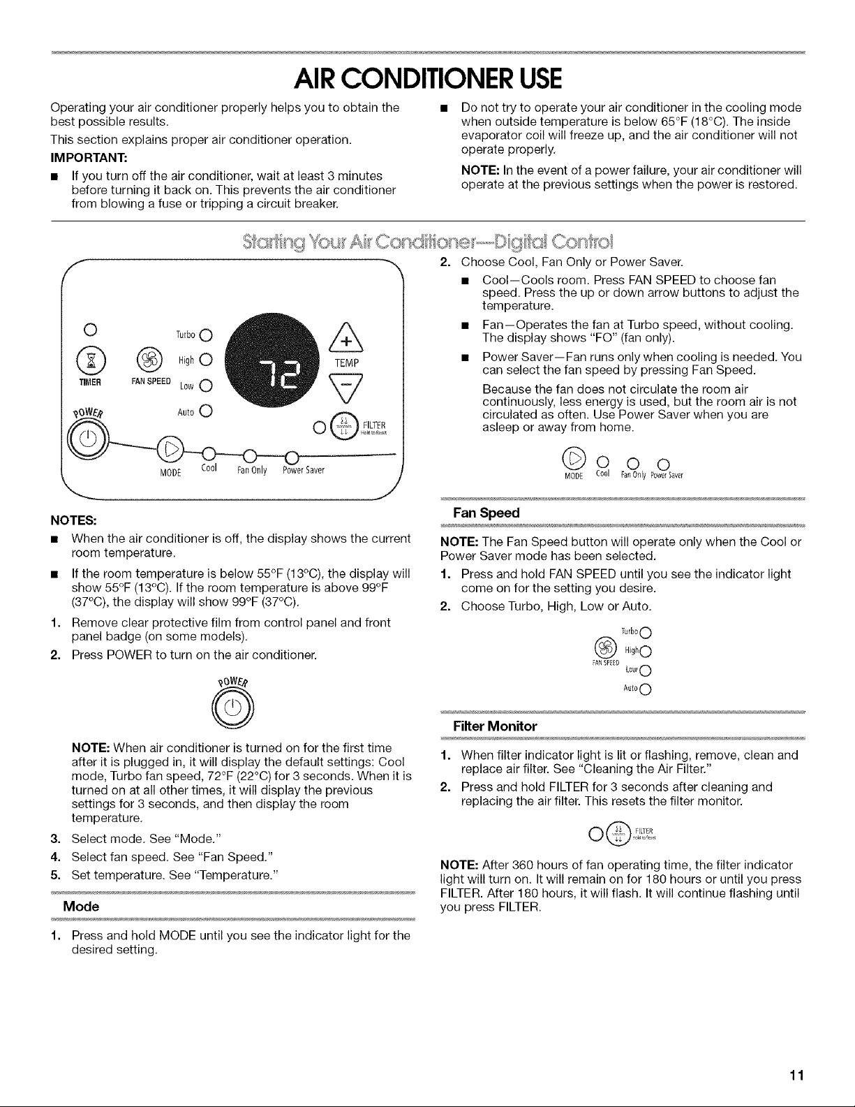
NOTES:
• When the air conditioner is off, the display shows the current
room temperature.
• If the room temperature is below 55°F (13°C), the display will
show 55°F (13°C). If the room temperature is above 99°F
(37°C), the display will show 99°F (37°C).
1. Remove clear protective film from control panel and front
panel badge (on some models).
2. Press POWER to turn on the air conditioner.
Do not try to operate your air conditioner in the cooling mode
when outside temperature is below 65°F (18°C). The inside
evaporator coil will freeze up, and the air conditioner will not
operate properly.
NOTE: In the event of a power failure, your air conditioner will
operate at the previous settings when the power is restored.
• Cool--Cools room. Press FAN SPEED to choose fan
speed. Press the up or down arrow buttons to adjust the
temperature.
The display shows "FO" (fan only).
• Fan--Operates the fan at Turbo speed, without cooling.
can select the fan speed by pressing Fan Speed.
Because the fan does not circulate the room air
continuously, less energy is used, but the room air is not
© o
MOD£ PowelSaver
Fan Speed
NOTE: The Fan Speed button will operate only when the Cool or
Power Saver mode has been selected.
1. Press and hold FAN SPEED until you see the indicator light
come on for the setting you desire.
2. Choose Turbo, High, Low or Auto.
Turb00
@ @0
FAN SPEED
LowO
Aut00
NOTE: When air conditioner is turned on for the first time
after it is plugged in, it will display the default settings: Cool
mode, Turbo fan speed, 72°F (22°C) for 3 seconds. When it is
turned on at all other times, it will display the previous
settings for 3 seconds, and then display the room
temperature.
3. Select mode. See "Mode."
4. Select fan speed. See "Fan Speed."
5. Set temperature. See "Temperature."
Mode
1. Press and hold MODE until you see the indicator light for the
desired setting.
Filter Monitor
1. When filter indicator light is lit or flashing, remove, clean and
replace air filter. See "Cleaning the Air Filter."
2. Press and hold FILTER for 3 seconds after cleaning and
replacing the air filter. This resets the filter monitor.
O@ FILTER
NOTE: After 360 hours of fan operating time, the filter indicator
light will turn on. It will remain on for 180 hours or until you press
FILTER. After 180 hours, it will flash. It will continue flashing until
you press FILTER.
11
 Loading...