

Whirlpool ACH 6601, ACH, 7601, ACH 9601 NSTRUCTIONS AND ADVICE FOR INSTALLING, USING AND SERVICING OF COOKERS
Page 1
Page 2

INSTRUCTIONS AND ADVICE FOR INSTALLING,
תירבעשומיש תוארוה
תירבע
USING AND SERVICING OF COOKERS
cm60x60 - cm70x60 and cm 90x60
םירונתה תקוזחתו שומיש ,הנקתהל עדימו תוארוה
מ"ס 90x60 -ו מ"ס 70x60 - מ"ס 60x60
ACH 6601
ACH 7601
ACH 9601
ENGLISH Instructions for use Page 3-30
31-57
םידומע
שומיש תוארוה
תירבע
Page 3
CONTENTS
IMPORTANT SAFETY INSTRUCTIONS 4-7
DESCRIPTION OF THE APPLIANCE 8-10
USER’S INSTRUCTIONS 11-17
TROUBLESHOOTING 18
TECHNICAL FEATURES 19-21
INSTRUCTIONS FOR THE INSTALLER 22-28
AFTER-SALES SERVICE 29
3
Page 4

IMPORTANT SAFETY INSTRUCTIONS
This manual and the appliance itself provide important safety advices, to be read and observed
at all times.
All safety advices give specic details of the potential risk present and indicate how to reduce
risk of injury, damage and electric shock resulting from improper use of the appliance. Carefully
observe the following instructions:
• The appliance must be disconnected from the power supply before carrying out any installation
work.
• The power cable must be long enough for connecting the appliance, once tted in its housing, to
the power supply socket.
• For installation to comply with current safety regulations, an all-pole disconnect switch with
minimum contact gap of 3 mm must be utilized.
• Do not use multiple plug adapters or extension leads.
• Do not pull the power supply cable in order to unplug the appliance.
• The electrical components must not be accessible to the user after installation.
• During and after use, do not touch the heating elements or interior surfaces of the appliance - risk
of burns. Do not allow the appliance to come into contact with cloths or other ammable materials
until all the components have cooled suciently.
• At the end of cooking, exercise caution when opening the appliance door, letting the hot air or
steam exit gradually before accessing the oven. When the appliance door is shut, hot air is vented
from the aperture above the control panel. Do not obstruct the vent apertures.
• Use oven gloves to remove pans and accessories, taking care not to touch the heating elements.
• Do not place ammable materials in or near the appliance: a re may break out if the appliance is
inadvertently switched on.
• Do not heat or cook sealed jars or containers in the appliance. The pressure that builds up inside
might cause the jar to explode, damaging the appliance.
• Do not use containers made of synthetic materials.
• Overheated oils and fats catch re easily. Always remain vigilant when cooking foods rich in fat and
oil.
• Never leave the appliance unattended during food drying.
• If alcoholic beverages are used when cooking foods (e.g. rum, cognac, wine), remember that alcohol
evaporates at high temperatures. As a result, there is a risk that vapours released by the alcohol may
catch re upon coming into contact with the electrical heating element.
4
Page 5

IMPORTANT SAFETY INSTRUCTIONS
You have purchased one of our products
for which we thank you. We are condent
that this new appliance, modern, functional
and practical, made with top quality
materials, will meet all your demands. This
new appliance is easy to use but before
installing and using it, it is important to
read this handbook through carefully. It
provides information for a safe installation,
use and maintenance. Keep this handbook
in a safe place for future reference.
The manufacturer reserves the right to
make all the modications to its products
that it deems necessary or useful, also
in your interests, without prejudicing
its essential functional and safety
characteristics. The manufacturer cannot
be held responsible for any inaccuracies
due to printing or transcription errors that
may be found in this handbook.
N.B.: the pictures shown in the gures in
this handbook are purely indicative.
• The installation, adjustments,
conversions and maintenance operations
listed in section «INSTRUCTIONS FOR
THE INSTALLER» must only be carried
out by qualied personnel .
• The installation of all-gas and combi
appliances must comply with the
standards in force.
• The appliance must only be used for
its original purpose, that is, cooking for
domestic use. Any other use is considered
improper and, as such, dangerous.
• The manufacturer cannot be held
responsible for any damage to persons
or property resulting from an incorrect
installation, maintenance or use of the
appliance.
• Once the packaging has been removed
from the outer surfaces and the various
inner parts, thoroughly check that the
appliance is in perfect condition. If
you have any doubts do not use the
appliance and call in a qualied person.
• The packaging materials used
(cardboard, plastic bags, polystyrene
foam, nails, etc.) must not be left with in
easy reach of children because they are
a potential hazard source. All packaging
materials used are environmentallyfriendly and recyclable.
• The electrical safety of this appliance
is only guaranteed if it is correctly
connected to a suitable earth system,
as prescribed by the electrical safety
standards. The manufacturer disclaims all
responsibility if these instructions are not
followed. Should you have any doubts,
seek the assistance of a qualied person.
• Before connecting the appliance ensure
that the rating plate data corresponds to
that of the gas and electricity supply (see
section «TECHNICAL FEATURES»).
The use of any electrical appliance
requires certain fundamental rules to
be observed:
• Do not touch the appliance with wet or
damp hands or feet.
• Do not use the appliance when barefoot.
• Do not pull the power cable to unplug
the appliance from the mains socket.
• Do not leave the appliance exposed to
the atmosphere (rain, sun, etc.).
WARNING: The appliance and its
accessible parts become hot during use.
Care should be taken to avoid touching
heating element. Children less than 8
years of age shall be kept away unless
continuously supervised.
The oven door glass and the accessible
5
Page 6

IMPORTANT SAFETY INSTRUCTIONS
parts will become hot when in use. To
avoid burns and scalds young children
should be kept away.
Young children should be supervised
to ensure that they not play with the
appliance.
This appliance can be used by children
aged from 8 years and above and persons
with reduced physical, sensory or mental
capabilities or lack of experience and
knowledge if they have been given
supervision or instruction concerning
use of the appliance in a safe way and
understand the hazards involved.
Children shall not play with the appliance.
Cleaning and user maintenance shall not
be made by children without supervision.
WARNING: ln order to prevent accidental
tipping of the appliance, for example by a
child climbing over the open oven door,
or too high weights are leant on the open
oven door, two chains must be screwed
on the back on the cooker and xed to the
wall with hooks. Ensure the chains are taut.
Please refer to instructions for installation.
Unattended cooking on a hob with fat or
oil can be dangerous and may result in re.
• Never try to extinguish a re with
water, but switch of the appliance and
then cover ame e.g. with a lid or a re
blanket .
• Danger of re: Do not store items on the
cooking surfaces.
• Do not use harsh abrasive cleaners or
sharp metal scrapers to clean the oven
glass door since they can scratch the
surface, which may result in shattering of
the glass. Never use sponges or abrasive
products, and solvents to remove stains
or adhesives on the painted or stainless
steel surfaces.
• The appliance is not intended to be
operated by means of an external timer
or separate remote-control system.
• Ensure that the appliance is switched o
before replacing the lamp to avoid the
possibility of electric shock.
• Do not use a steam cleaner to clean a
hob, oven or range.
• The appliance is to be placed directly on
the oor and shall not be mounted on
a base.
• Keep the appliance clean. Food residues
can be a re hazard.
• When the oven is not in use, do not use
it to store foodstus or containers: if it
is accidentally turned on, it can cause
damage and accidents.
• If an electrical socket near the appliance is
used, ensure that the cables of any other
electrical appliances do not come into
contact with the oven and are at a sucient
distance from the hot parts of the oven.
• After using the appliance ensure that
all the controls are in the o or closed
position, and check that the “0” on the
knob corresponds with the symbol “•“
printed on the front panel.
• Before carrying out any kind of
cleaning, adjustment, conversion or
maintenance operation, disconnect
the appliance from the electricity
supplies.
• In case of problems and/or malfunction,
turn o the appliance and disconnect
it from the mains electricity supplies,
Do not attempt to tamper with it. Any
repairs, or adjustments must be carried
out exclusively by qualied personnel.
For this reason, we recommend that you
to contact your nearest Service Centre
specifying the model of your appliance
6
Page 7

IMPORTANT SAFETY INSTRUCTIONS
and the type of problem.
The appliance was designed and made in
accordance with the European standards
listed below:
=> EN 30-1-1, EN 30-2-1 and EN 437
plus subsequent amendments
(gas)
=> EN 60 335-1 and EN 60 335-2-6 (electrical)
plus relative amendments
The appliance complies with the prescriptions
of the European Directives as below:
=> 2006/95 EC concerning electrical safety
(BT).
=> 2004/108 EC concerning electromagnetic
compatibility (EMC).
=> 2009/142/ EC concerning gas safety.
Oven accessories that could come into
contact with foodstus are made with
materials that comply with the provisions
of the 89/109 EC directive dated 21/12/88.
This product complies with EU Directive
2002/96/EC.
The crossed-out dustbin symbol reported on
the appliance indicates that the appliance
must be disposed of separately from other
domestic refuse at the end of its useful life.
It must therefore be delivered to a waste
recycling centre specically for electric and
electronic equipment or returned to the
retailer at the moment of purchase of a new
equivalent appliance.
The user is responsible for delivering the
appliance to the appropriate collection
centre at the end of its useful life, Failure to
do so may result in a ne, as provided for by
laws governing waste disposal.
Dierential collection of waste products
for eventual recycling, treatment and
environmentally friendly disposal helps
reduce possible negative eects on the
environment and health, and also enables
the materials making up the product to be
recycled.
For more detailed information on the
available refuse collection systems, refer
to the local Municipal Solid Waste disposal
centre or the shop where the product was
purchased.
Producers and importers are responsible
for fullling their obligations as regards
recycling, treatment and environmentally
friendly disposal by directly or indirectly
participating in the collection system.
7
Page 8

DESCRIPTION OF THE APPLIANCE
PRESENTATION
The cookers are tted with a hob to gas,
and a electric oven;. the latter can be either
conventional or forced type (with fan).
The burners are equipped with safety
thermocouples (Tc) (g. 6).
Each knob on the front panel has a diagram
printed above it showing to which burner it
refers. The combination of the dierent sized
burners oers the possibility of various types of
cooking.
If the cooker has electronic clock with end-ofcooking which makes it possible to use the oven
without supervision, to guarantee the customer
a good and safe use of the appliance it has a
safety thermostat that starts working should
the main thermostat malfunction. In such an
event, the electricity is interrupted temporarily:
do not attempt to repair it yourself but turn
the appliance o and contact your nearest
Assistance Centre.
There are grooves in the oven walls, called
steps (g. 1) on which we can place the
accessories listed below (g. 2). The type and
the quantity of accessories vary according
to the model:
• oven shelf (A)
• drip tray or drip pan (B)
• cake or pizza tray (C)
1
8
2
Page 9
DESCRIPTION OF THE APPLIANCE
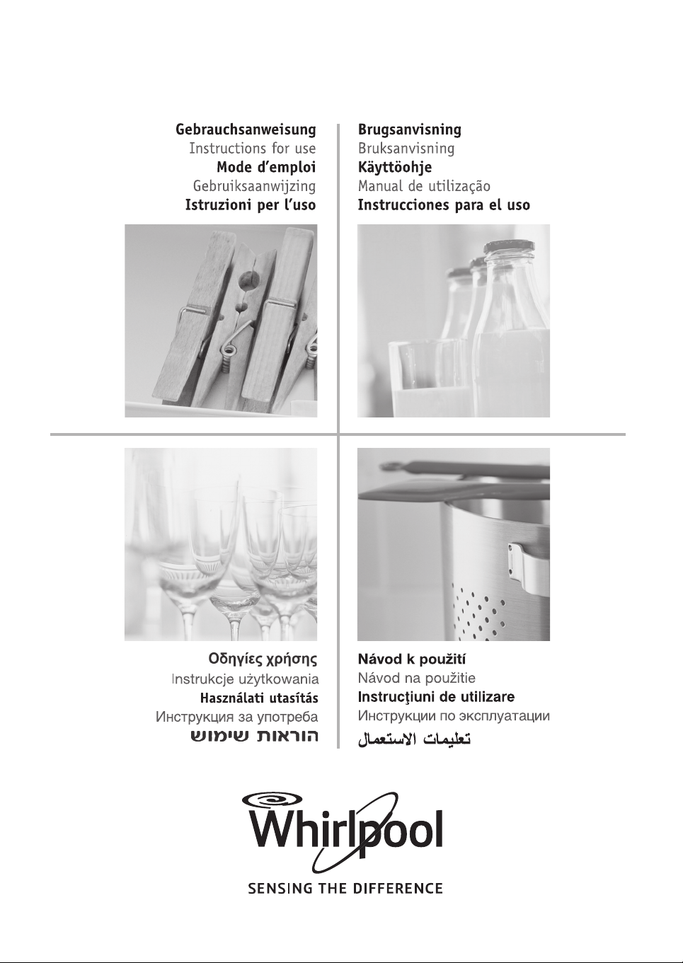
DESCRIPTION OF THE CONTROLS
HOB GAS BURNER KNOB (A)
By rotating the knob in an anticlockwise
direction, the following symbols appear:
0
= Closed position
= “Full on” position
= “Reduced rate” position
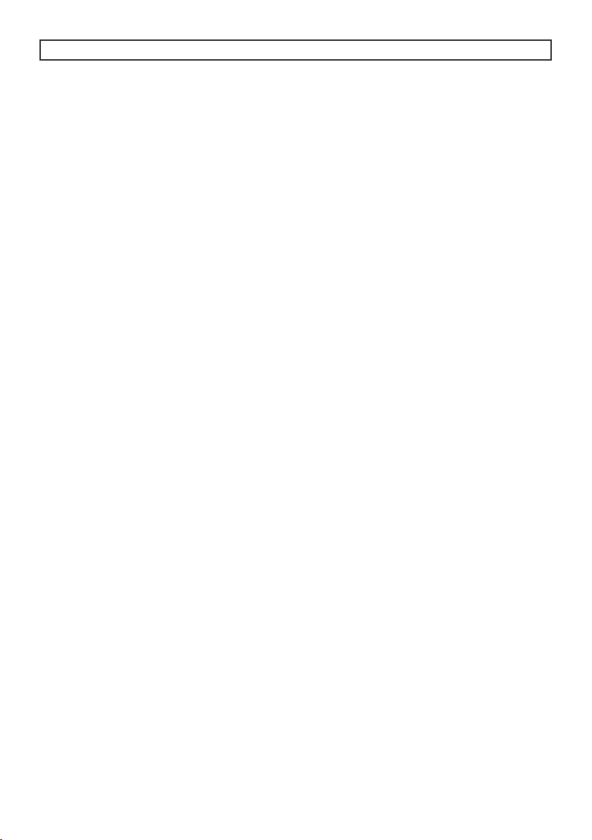
THERMOSTAT KNOB FOR THE FAN OVEN (B)
By turning the oven knob clockwise we will nd
the dierent oven temperature values (from
50°C to Maxi).
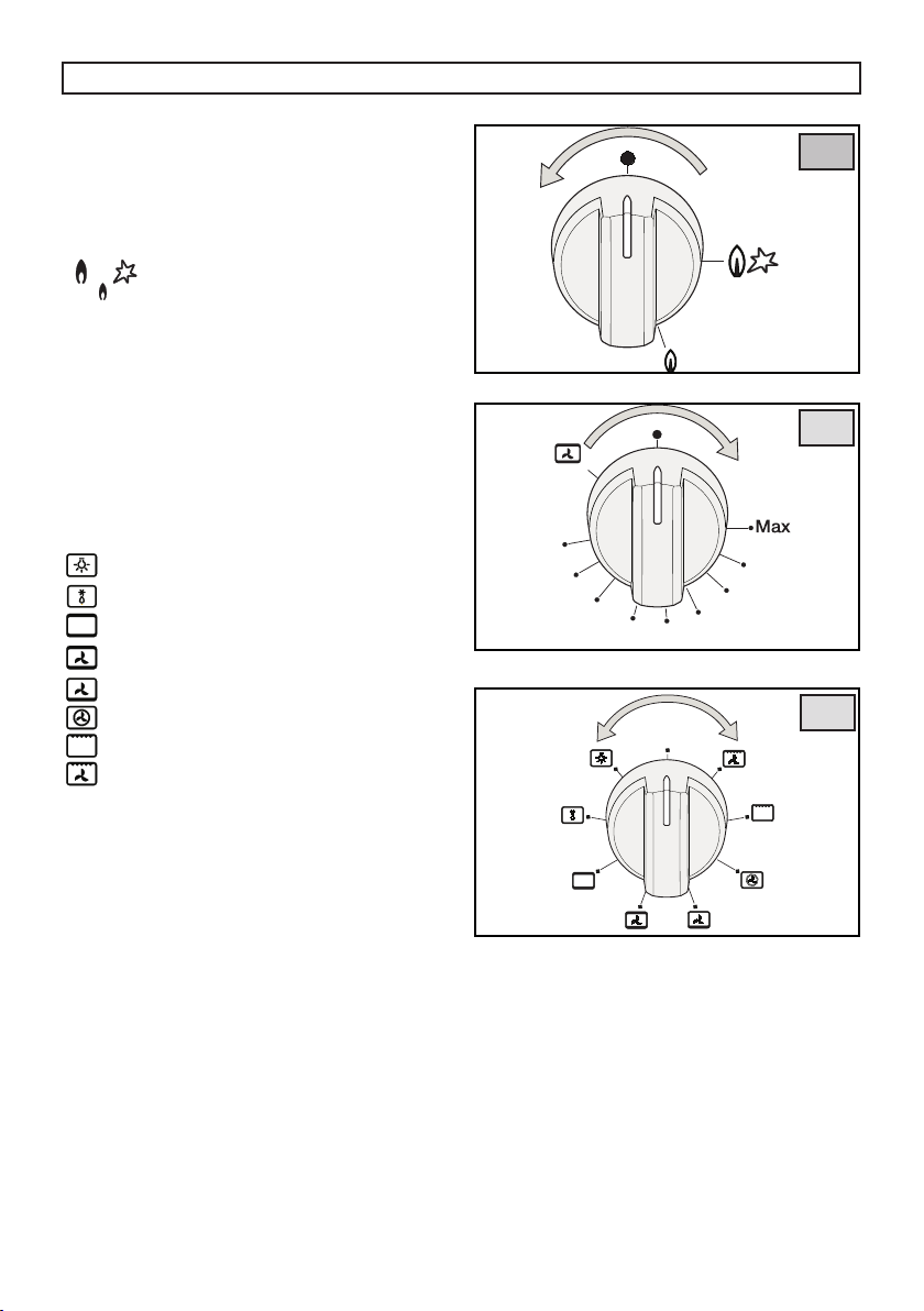
FAN OVEN FUNCTION SELECTOR KNOB (8)
(C)
By turning the knob to the right or to the left
we will nd the following symbols:
0
= Oven o
= Oven light on, which stays on for all
functions
= Fan on
= Top and bottom heating elements on
= Top and bottom heating elements and fan
on
= Bottom heating element and fan on
= Rear heating element and fan on
= Grill
= Grill heating element and fan on
A
b
C
YELLOW WARNING LIGHT
When lit it indicates that either the electric
oven or electric grill is working. While the oven
is being used the light will switch o when the
set temperature is reached. During baking it
is normal for the yellow light to switch on and
o several times as the oven temperature is
controlled.
RED WARNING LIGHT
When lit it indicates that one or more of the
hob electric plates is on if the hob is mixed or
electric, or one of the oven electric components.
9
Page 10
DESCRIPTION OF THE APPLIANCE
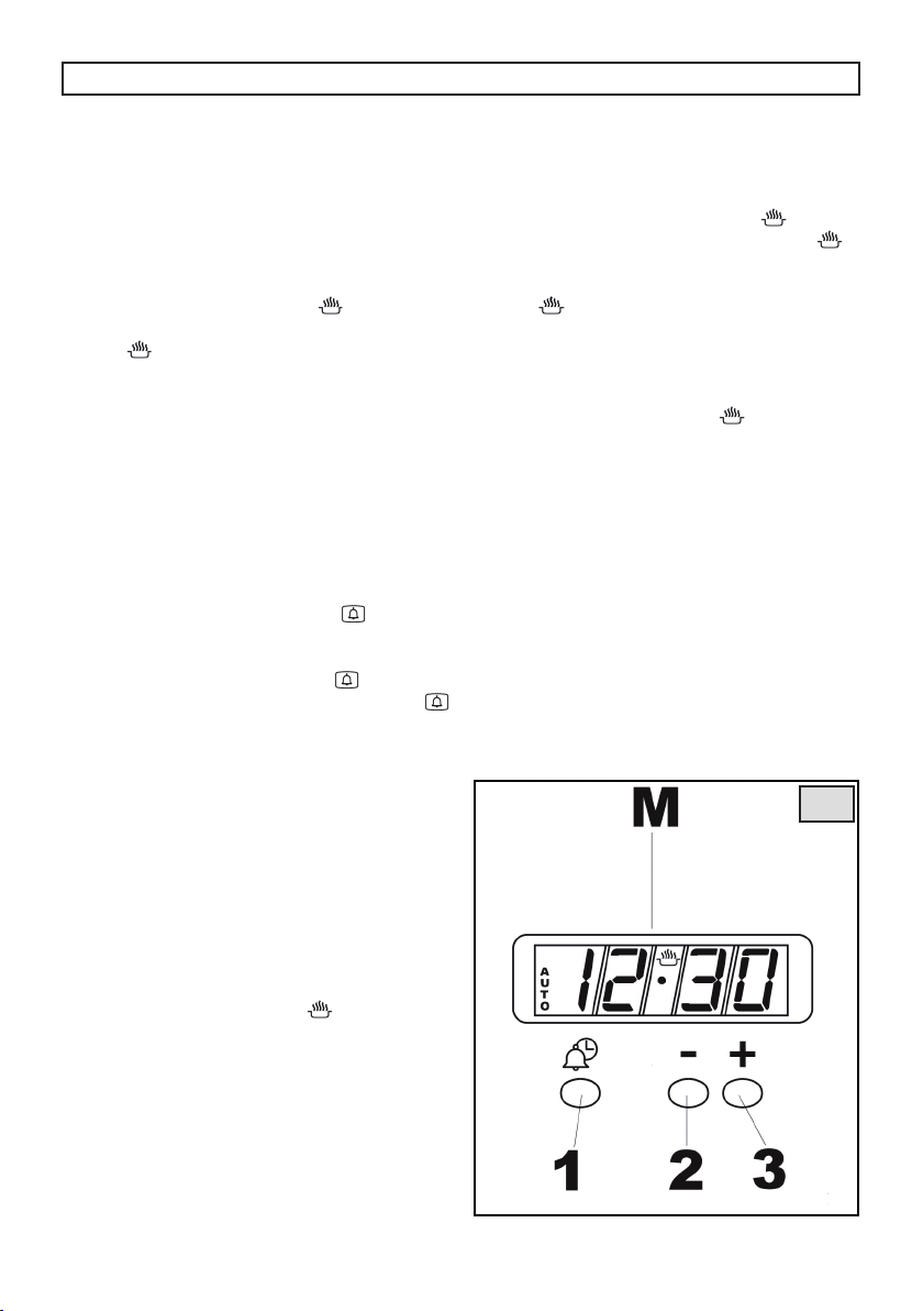
ELECTRONIC PROGRAMMER «TOUCH» (E)
Setting the time.
After connecting to mains or after a power
cut, symbol “A” and “0,00” will both ash
simultaneously on the display.
Keep pressed for some seconds simultaneously
+ and - buttons or just MODE button, till when
symbol “A” turn o and symbol
Time can be set just when the dot beneath the
symbol
Time cannot be adjusted during cooking
program run.
If time is selected while a automatic cooking
program is running, this is deleted.
Program selection
Keep pressed for some seconds MODE
button and pressing it in turns, the following
programs are selected:
1. Minute Minder
The time turns o, the symbol
and with + and - buttons is possible to select
the time alarm. At the end of the set time, the
buzzer will start and the symbol
turn o the buzzer and turn o the symbol
keep pressed for some seconds MODE button.
The minute minder program runs
independently of other cooking programs.
2. Semiautomatic Program with Duration
Select with + and - buttons the duration. The
time of the day turns o, symbol “A” and “dur”
ash. At the end of the set time, the buzzer will
start and the symbol “A” ashes. To turn o the
buzzer press MODE button.
Now the oven is o. Keep pressed for some
seconds simultaneously + and - buttons or just
MODE button and the symbol
ashes.
or End Time
turn on.
turns on
ashes. To
is illuminated.
3. Fully automatic program with Duration
and End time
Select with + and - buttons the duration and
the end time. The time of the day turns o,
symbol “A” and “End” ash. Symbol turns o
and the symbol “A” turns on. The symbol
illuminated again when the cooking starts. At
the end of the set time, the buzzer will start, the
symbol
To turn o the buzzer press MODE button.
Now the oven is o. To set the programmer
on manual operation keep pressed for some
seconds simultaneously + and - buttons or just
MODE button and the symbol
Changing/Clearing programs
Each program can be cleared keeping pressed
for some seconds simultaneously + and buttons. Symbol “A” turns o.
Each program can be changed keeping
pressed for some seconds MODE button and
then pressing it in turns to the function to be
changed. The adjustment can be done with +
and - buttons.
Is it possible to check whenever the progress
of program keeping pressed for some seconds
MODE button and then pressing in turns to the
function to be checked.
turns o and the symbol “A” ashes.
is illuminated.
is
E
10
Page 11

USER’S INSTRUCTIONS
HOB: GENERAL NOTES ON SAFETY
• When using the burners or the plates, do not
leave the appliance unsupervised. Ensure
that children do not play with the appliance.
In particular, make sure that pan handles
are positioned correctly and supervise the
cooking of foods which use oils and fats, as
these are highly inammable.
• Do not use aerosols or sprays near the
appliance when it is in use.
• Even after use, the burners or the plates
remain hot for a long period; to avoid
burning, do not place hands or other objects
on them.
• After using the appliance, ensure that all the
controls are in the closed or o position.
When a gas cooker is being used it
produces heat and humidity in the room
where it is installed. For this reason the
room must be well ventilated, keeping
the natural ventilation openings free and
switching on the mechanical aeration
system (paragraph «VENTILATION and
LOCATION AND AERATION).
used for a long time additional aeration
may be necessary, for instance, opening
a window, or a more eective aeration by
increasing the power of the mechanical
system if there is one.
If the cooker is
LIGHTING THE BURNERS
Lighting of burners equipped with safety
thermocouples (g. 6, ref. TC)
When the burners are equipped with
safety thermocouples you have to turn
counterclockwise to the “Full on“ position, the
knob corresponding to the burner you wish
to use, then press the knob and repeat the
operations described previously. Once lit, keep
the knob pressed for about 10 seconds.
4
Optimum use of the burners
To get the maximum yield with the minimum
consumption of gas it is handy to keep the
following points in mind:
• Once the burner has been lit, adjust the
ame according to your needs.
• Use an appropriately sized pan for each
burner (see the table below and g. 4).
• When the content of the pan start to boil, turn
the knob down to “Reduced rate position”
(small ame).
Burners Ø pan cm
Ultra-Rapid 22÷24
Rapid 20÷22
Semi-rapid 16÷18
Auxiliary 12÷14
OVEN: GENERAL SAFETY INSTRUCTIONS
• Do not leave the oven unsupervised during
use. Ensure that children do not play with the
appliance.
• Always grip the centre of the oven door when
opening. Do not practice excessive pressures
on the door when it is open.
• Do not worry if condensation forms on the
door and on the internal walls of the oven
during cooking. This does not compromise
its eciency.
• When opening the oven door, be very careful
of scalding vapours.
• The appliance becomes very hot during use.
Do not touch the heating elements inside
the oven. Wear oven gloves when placing or
removing pans from the oven.
• When inserting or removing food from
the oven, check that excess juices do not
overow onto the oven base (oils and fats are
highly inammable when overheated).
• Use containers that will resist the
temperatures indicated on the thermostat
knob.
• For good results during cooking, we strongly
recommend not to cover the base of the
oven or the grill with aluminium foil or other
materials.
11
Page 12

USER’S INSTRUCTIONS
• When grilling always put a little water in the
grill pan. The water prevents the grease from
burning and from giving o bad smells and
smoke. Add more water during grilling to
compensate for evaporation.
• After using the appliance ensure that all the
controls are in the o position.
• WARNING!!! During and after use, the oven
door glass and the accessible parts can be
very hot, therefore keep children away from
the appliance.
IMPORTANT!!
Always keep the oven door closed during
baking or grilling.
WHAT TO DO THE FIRST TIME YOU USE THE
OVEN
If the appliance has a programming
accessory, place it on the manual position,
and, before cooking for the rst time, ensure
the oven is empty and its door closed, heat the
oven at maximum temperature for 2 hours. This
will allow the protective coating on the interior
of the oven to be burnt o and dissipate the
associated smells. During this time do not stay
in the same room and keep it aerated.
After the hour or so has elapsed leave the oven
to cool down and then clean its interior with
hot water and a mild detergent. Also wash the
accessories (shelves, trays, drip pan, spit..) prior
to use.
Prior to any cleaning, disconnect the
appliance from the electricity mains.
HOW TO USE THE MULTIFUNCTION
OVEN
DEFROSTING AT ROOM
TEMPERATURE
Turn the selector knob to the symbol and place
the food you want to defrost inside the oven.
The length of time required depends on the
quantity and type of food.
Selecting this function will only activate the
fan. Mild air circulation around frozen food will
slowly defrost it. It is particularly suitable for
fruit and cakes.
TRADITIONAL COOKING
Turn the selector knob to the symbol and
adjust the thermostat knob to suit the desired
temperature.
If pre-heating is recommended wait till the
thermostat yellow led turns o before placing
foods inside the oven. This option turns on
both bottom and top heating units, evenly
distributing heat on your foods.
This type of cooking is ideal for all kind of foods
(meats, sh, bread, pizzas, cakes..).
COMBINED TRADITIONAL + FAN
COOKING
Turn the selector knob to the symbol and
adjust the thermostat knob to suit the desired
temperature.
If pre-heating is recommended wait till the
thermostat yellow led turns o before placing
foods inside the oven. This option turns on
both bottom and top heating units, and heat is
distributed by fan ventilation.
This combination is suitable for rapid cooking
and allows for the use of more plates positioned
on the dierent levels of the oven (g. 5).
12
Page 13

USER’S INSTRUCTIONS
DEFROSTING + WARM UP BY HOT AIR
Turn the selector knob to the symbol and set
the temperature on the thermostat knob,
now place the food inside the oven. Selecting
this function will activate the bottom heating
unit and its heat is distributed by the fan.
This function is particularly recommended to
defrost and warm up ready-made meals.
FAN + REAR HEATING COMBINED
COOKING
Turn the selector knob to the symbol and
set the thermostat knob to the desired
temperature, then place your food the oven. If
oven needs pre-heating wait till the thermostat
yellow led turns o before placing foods inside
it. This function activates the rear heating unit
and the fan distributes the heat produced. This
combination allows for a fast and even cooking
of several dierent foods placed on the diverse
levels of the oven (g. 5).
CONVETIONAL GRILL COOKING
Turn the selector knob to the symbol and set the
thermostat knob to the desired temperature.
Selecting this function the top central heating
element turns on and heat is distributed
directly on food surface.
Apart from grilling, this function is ideal to add
a golden roast to your recipes or to toast bread
slices.
The grill function automatically activates
the eventual spit. When you use the grill, do
not forget to place the drip pan beneath it to
collect any sauce dripping, as suggested in the
“USEFUL COOKING TIPS “ section.
FAN GRILL COOKING
Turn the selector knob to the symbol and set the
thermostat knob to the desired temperature.
Selecting this function the top central heating
element turns on and heat is distributed by the
fan. This procedure mitigates the direct heat on
food surface and uses milder temperatures. It
is therefore recommended for an even golden
and crispy nish touch, ideal for whole sh and
poultry.
When you use the grill, do not forget to
place the drip pan beneath it to collect any
sauce dripping, as suggested in the “USEFUL
COOKING TIPS “ section.
13
5
Page 14

USER’S INSTRUCTIONS
USEFUL COOKING TIPS
Cakes and bread:
• Heat the oven for at least 15 minutes before
you start cooking bread or cakes.
• Do not open the door during baking
because the cold air would stop the yeast
from rising.
• When the cake is cooked turn the oven o
and leave it in for about 10 minutes.
• Do not use the enamelled oven tray or drip
pan, supplied with the oven, to cook cakes
in.
• How do you know when the cake is
cooked? About 5 minutes before the end of
cooking time, put a cake tester or skewer in
the highest part of the cake. If it comes out
clean the cake is cooked.
• And if the cake sinks? The next time use less
liquids or lower the temperature 10°C.
• If the cake is too dry: Make some tiny holes
with a toothpick and pour some drops of
fruit juice or spirits on it. The next time,
increase the temperature 10°C and set a
shorter cooking time.
• If the cake is too dark on top: the next time
put the cake on a lower shelf, cook it at a
lower temperature and longer.
• If the top of the cake is burnt: cut o
the burnt layer and cover with sugar or
decorate it with cream, jam, confectioner’s
cream, etc..
• If the cake is too dark underneath: the next
time place it on a higher shelf and cook it at
a lower temperature.
• If the cake or bread is cooked nicely outside
but is still uncooked inside: the next time
use less liquids, cook at a lower temperature
and longer.
• If the cake will not come out of the tin: slide
a knife around the edges, place a damp
cloth over the cake and turn the tin upside
down. The next time grease the tin well and
sprinkle it with our or bread crumbs.
• If the biscuits will not come away from the
baking tray: put the tray back in the oven for
a while and lift the biscuits up before they
cool. The next time use a sheet of baking
parchment to prevent this happening
again.
Meat:
• If, when cooking meat, the time needed is
more than 40 minutes, turn the oven o 10
minutes before the end of cooking time to
exploit the residual heat (energy saving).
• Your roast will be juicier if cooked in a closed
pan; it will be crispier if cooked without a
lid.
• Normally white meat, poultry and sh need
medium temperatures (less than 200°C).
• To cook “rare” red meats, high temperatures
(over 200°C) and short cooking times are
needed.
• For a tasty roast, lard and spice the meat.
• If your roast is tough: the next time leave
the meat to ripen longer.
• If your roast is too dark on top or
underneath: the next time put it on a higher
or lower shelf, lower the temperature and
cook longer.
• Your roast is underdone? Cut it in slices,
arrange the slices on a baking tray with the
gravy and nish cooking it.
Grilling:
• Sparingly grease and avour the food
before grilling it.
• Always use the grill pan to catch the juices
that drip from the meat during grilling.
• Always put a little water in the drip pan. The
water prevents the grease from burning
and from giving o bad smells and smoke.
Add more water during cooking because it
evaporates.
• Turn the food half way through cooking.
• If you are grilling fatty poultry (goose)
pierce the skin so the fat can drip away.
The aluminium can be easily corroded if
it comes into contact with organic acids
present in the foods or added during
baking (vinegar, lemon juice). Therefore
it is advised not to put directly the foods
on aluminium or enamelled trays, but
ALWAYS use the proper oven paper.
14
Page 15
USER’S INSTRUCTIONS
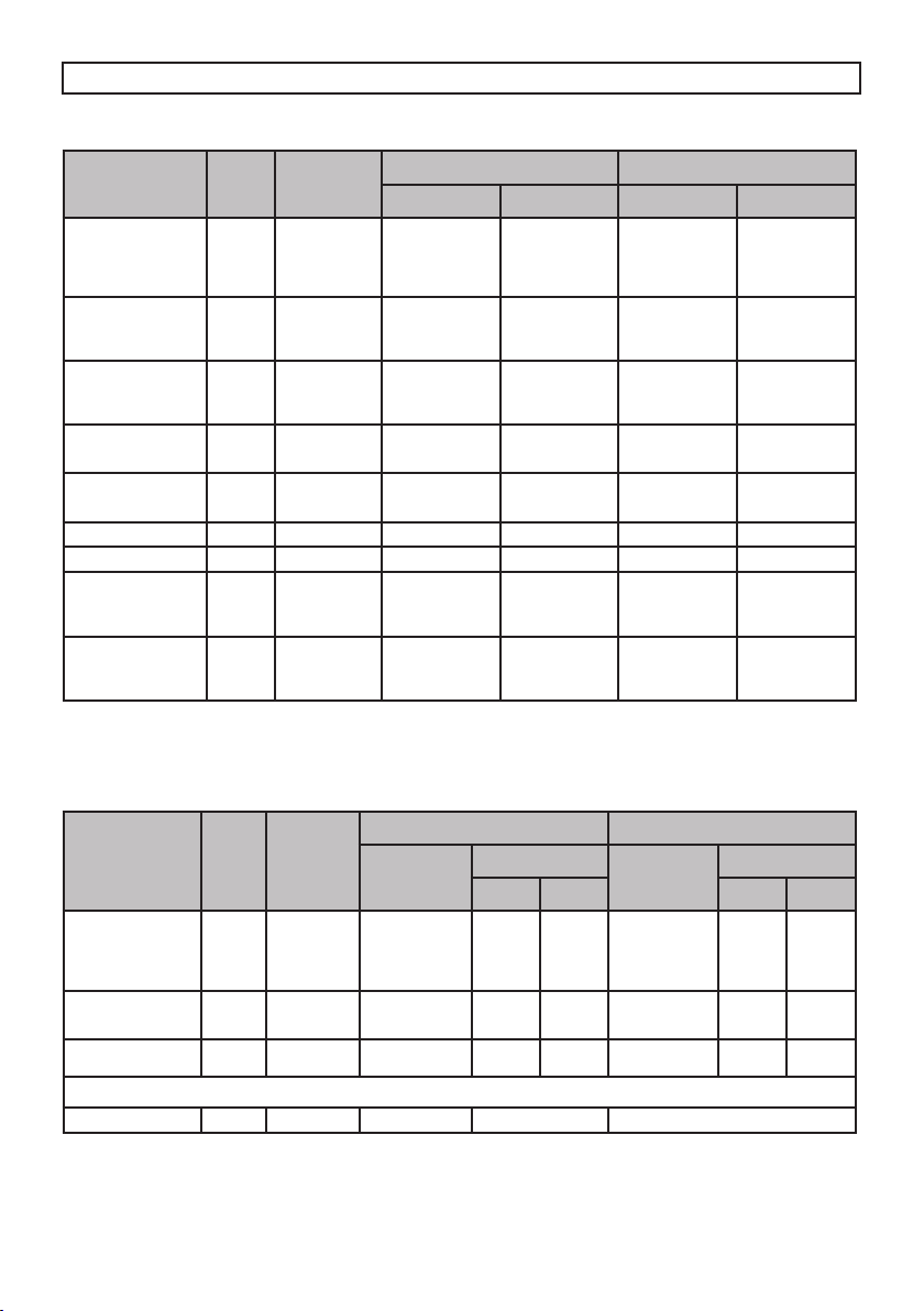
COOKING/BAKING TABLE
Cooking by natural convenction Cooking by forced convenction
Temperatures
in °C
200-225
200-225
200-225
200-225
200-Max
200-Max
200-Max
200-225
200-225
200-225
200
175
210-225
210-225
225-Max 25-30 225-Max 20-25
225-Max 20-25 220 20
190
200
200
190
200
200
Cooking time
in minutes
100-120
40-50
100-120
100-120
50-60
60-70
50-60
80-90
100-120
90-110
30-35
20-25
60-75
60-75
15
20
40-45
52
65
45
Temperatures
in °C
190
190
190
190
200-Max
200-Max
200-Max
190
190
190
170-190
160-170
225-Max
225-Max
170-190
190-200
190-200
170-190
190-200
190-200
(with fan)
Cooking time
in minutes
100-120
100-120
100-120
90-110
80-100
GRILLING TABLE
Cooking by natural convenction
Cooking time
Temperatures
in °C
225-Max
200-225
225
225-Max
225-Max
225-Max 2-3 2-3 200 2-3 2-3
SPIT (*)
in minutes
1st side
12-15
5
20
=
=
2nd
side
12-15
Cooking by forced convenction
Temperatures
in °C
5
20
=
=
200
200
200
=
=
(with fan)
Cooking time
1st side
15
10
in minutes
=
=
7
40-50
50
60
50
70-80
25-30
15-20
30-40
30-40
15
20
40-45
45
65
45
2nd
side
10
=
=
10
7
kg
1
1
1
1
1
1
1
1
1
1
1
1
2,5
2,5
0,8
0,8
0,8
1
Position of
the oven
shelf from
the bottom
2
1
2
1
2
2
2
2
2
2
2
2
1
1
2
2
2
2
2
2
2
2
Position of
the oven
shelf from
the bottom
3
3
2
3
3
3
Foods
MEAT
Roast veal
Roast beef
Roast pork
Roast lamb
GAME
Roast hare
Roast pheasant
Roast partridge
POULTRY
Roast chicken
Roast turkey
Roast duck
FISH
Roast sh
Casseroled sh
BAKED PASTA
Lasagne
Cannelloni
PIZZA 1
BREAD 1
PASTRIES
Biscuits in general
Shortcrust pastry
Victoria sponge 0,8
CAKES
Angel cake
Fruit cake
Chocolate cake
The values given in the tables (temperatures and cooking times) are approximate and may vary according to each person’s
cooking habits. This table gives cooking times on only one shelf. If you are cooking with a fan oven and you are using more
than one shelf (placing the shelves on the 1st and 3rd or 2rd and 4rd position) cooking time will be about 5 to 10 minutes
longer.
Foods
MEAT
Chop
Beefsteaks
Half chicken (each
half 0.5 kg)
FISH
Trout
Sole
BREAD
Toast
CHICKEN 1.3 2 225-Max 80-90 =
The values given in the tables (temperatures and cooking times) are approximate and may vary according to each person’s
cooking habits. In particular, temperatures and times for grilling meat will greatly depend on the thickness of the meat and
on personal tastes.
Weight
Weight
kg
0,50
0,15
0,42
0.20
15
Page 16

USER’S INSTRUCTIONS
CLEANING AND MAINTENANCE
• Prior to any maintenance work or
cleaning, disconnect the appliance from
the electricity mains.
• Do not use a steam cleaner to clean this
appliance.
• Do not wash the parts if they are still hot.
• Do not use metal pads, abrasive powders
or corrosive spray products for cleaning
• Do not leave vinegar, coee, milk, salty
water or the juice of lemon or tomato
on enamelled surfaces for any length of
time.
• Switch o the oven before removing the
fan guard for cleaning. Replace the guard
after cleaning
HOT PLATE
The enamelled steel pan supports, enamelled
burner caps and burner heads need to be
cleaned after each time they are used with
warm soapy water, rinsed and then dried well
to keep them in good condition.
WARNINGS:
• After cleaning, check that the heads burners
and the relative burner caps, are correctly
positioned in their housings (g. 6).
• Take care not to disturb the ignition spark
plugs or ame failure devices.
• If you nd a tap is dicult to open or close
do not force it but call for technical assistance
urgently.
• After use, to keep them in good condition,
the hot plates should be treated with specic
products, easily found in the shops, to keep
the surfaces clean and shining. This will also
prevent rust from forming.
• If any liquid spills over it must always be
removed with a sponge.
STRUCTURE
All the cooker parts (in enamelled or painted
metal, steel, or glass) should be cleaned
frequently with warm soapy water and then
rinsed and dried with a soft cloth.
DO NOT use rough or abrasive materials or
sharp metal scrapers to clean the oven glass
doors as they could scratch and cause the glass
to break
NEVER use sponges or abrasive products, and
aromatic or aliphatic solvents to remove stains
or adhesives on the painted or stainless steel
surfaces.
OVEN CAVITY
Do not spray or wash the thermostat
bulb with acid based products (check the
product label before use).
The manufacturer cannot be held liable for
any damage caused by incorrect cleaning.
The oven cavity should be cleaned after each
use to remove cooking residuals and or grease
or sugar which, if burnt on when the oven is
used again, will form deposits or unremovable
stains as well as unpleasant smells.
To maintain the shine of the enamelled parts,
clean them with warm soapy water, rinse
and dry them thoroughly. ALWAYS wash the
accessories used.
OVEN SIDEWALL GRIDS (g. 7)
To allow for a better cleaning of the side grids,
you can extract them this way:
1. Push with a nger on the last of the slots to
release the grid from its hold.
2. Lift it towards the top and extract the grid.
To put them back into place, reverse the order of
this operation.
6
16
7
Page 17

USER’S INSTRUCTIONS
OVEN DOOR REMOVAL
The oven door can be removed to give easier
access to the oven when cleaning.
To remove, proceed as follows:
• Open the oven door and insert rivet or nail
(R) in the hole (F) of the hinge (g. E).
• Partially close the door, forcing it upwards at
the same time to free stop tooth and hinge
sector.
• Once the hinge is free, pull the door forwards
tilting it slightly upwards to free sector.
• To reassemble proceed in the reverse order,
paying attention to the correct position of
sectors.
REPLACING THE OVEN LAMP (g. 9)
Ensure the appliance is switched o before
replacing the lamp to avoid the possibility
of electric shock..
IIn the event one or both oven lamps need
replacing, the new lamps must comply with the
following requisites: 15 W - 230 V~ - 50 Hz - E
14 - and must be resistant to high temperature
(300°C).
Draw out the side guide rails as described
above.Then, remove the glass protection
cap (V) from the bulb socket, lifting it with a
screwdriver (C) placed between the cap and
the oven wall and replace the lamp. Fit the
accessories back in reverse order.
E
9
The lamp used in the appliance is specically
designed for electrical appliances and is not
suitable for household room illumination
(Commission Regulation (EC) No 244/2009).
OVEN SEAL
The oven seal guarantees the correct
functioning of the oven. We recommend you:
• clean it, avoiding abrasive tools or products.
• check its state now and then.
If the oven door seal has become hard or
is damaged, contact our Service Centre
and avoid using the oven until it has been
repaired.
17
Page 18
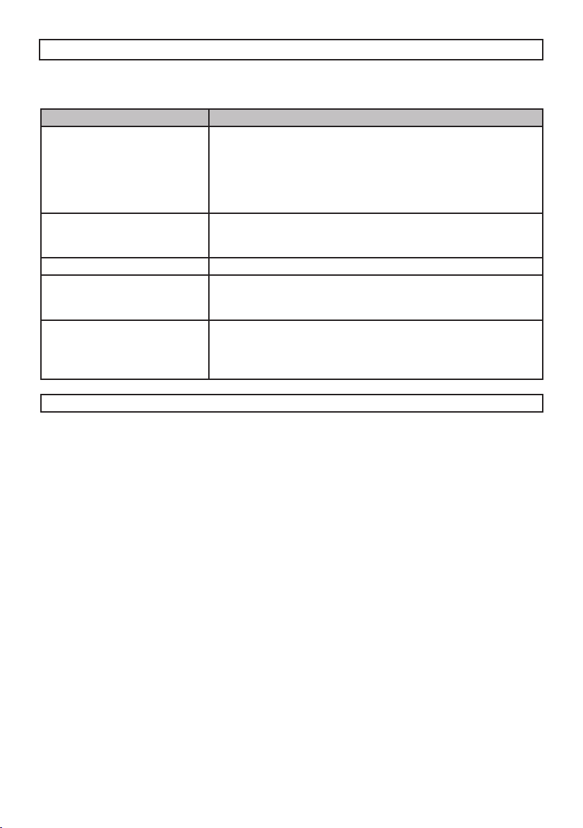
TROUBLESHOOTING
Some of the problems occur because of simple maintenance oversights or operation mistakes and
can easily be resolved without having to call for technical assistance.
PROBLEM REMEDY
The appliance is not working • Make sure the gas cock is open
The electric oven is not working
The thermostat is not working • Call our Service Centre
The electric thermostat warn-
ing light does not switch on
during use
The oven light does not switch on• Make sure the lamp is rmly screwed in place
Warning: Servicing should be carried out only by authorised personnel.
• Check the plug is in
• Check that the knobs are set correctly for cooking and then
repeat the operations given in the handbook
• Check the electrical system safety switches (RCD). If there is
failure in the system call an electrician in.
• Check that the programmer accessory, if there is one, is on the
manual position and then repeat the operations described in
the manual
• Turn the thermostat round to a hotter temperature
• Turn the selector round to a dierent function
• Buy a lamp for high temperatures at one of our Service Centre
and t it following the instructions given in the paragraph
«REPLACING THE OVEN LAMP».
18
Page 19

TECHNICAL FEATURES MODEL ACH 6601 (cm 60x60)
BURNER TECHNICAL DATA TABLE
Burners
N. Denomination mbar g/h L/h 1/100 mm Min Max “X”mm 1/100 mm
6 Ultra-Rapid
3 Semi-rapide
4 Auxiliary
Operating
Pressure Gas
LPG - Butane
LPG - Propane
Natural
LPG - Butane
LPG - Propane
Natural
LPG - Butane
LPG - Propane
Natural
28-30
37
20
28-30
37
20
28-30
37
20
Rate
236
232
131
129
73
71
309
171
95
Diameter
Injectors
95
95
125-K
68
68
98-Z
51
51
75-X
Heat Input
1350
1350
1350
600
600
600
400
400
400
3250
3250
3250
1800
1800
1800
1000
1000
1000
Air
regulation
sleve
opening
= 62
= 34
= 28
By-pass
BURNER DISPOSITION
OUTSIDE COOKER DIMENSIONS (g.10)
Type
height h mmwidth Lmmdepth P
cooker
60 x 60 850 600 600
ELECTRIC COMPONENTS
Description Nominal data
Lower heating element of the oven
Top heating element of the oven-grill
Rear heating element
Oven lamp
Rear fan
Cable type and section
1400 W a 240 V
800 + 1800 W
2000 W
15 W - E 14 – T 300
25..29 W
H05 RR-F 3x1.5
mm
10
19
Page 20

TECHNICAL FEATURES MODEL ACH 7601 (cm 70x60)
BURNER TECHNICAL DATA TABLE
Burners
N. Denomination mbar g/h L/h 1/100 mm Min Max “X”mm 1/100 mm
5 Ultra-Rapid
3 Rapide
3 Semi-rapide
4 Auxiliary
Operating
Pressure Gas
LPG - Butane
LPG - Propane
Natural
LPG - Butane
LPG - Propane
Natural
LPG - Butane
LPG - Propane
Natural
LPG - Butane
LPG - Propane
Natural
28-30
37
20
28-30
37
20
28-30
37
20
28-30
37
20
Rate
236
232
218
214
131
129
73
71
309
276
171
95
Diameter
Injectors
95
95
125-K
88
88
117-Y
68
68
98-Z
51
51
75-X
Heat Input
1350
1350
1350
800
800
800
600
600
600
400
400
400
3250
3250
3250
3000
3000
2900
1800
1800
1800
1000
1000
1000
Air
regulation
sleve
opening
= 62
= 44
= 34
= 28
By-pass
BURNER DISPOSITION
OUTSIDE COOKER DIMENSIONS (g.10)
Type
height h mmwidth Lmmdepth P
cooker
70 x 60 850 700 600
ELECTRIC COMPONENTS
Description Nominal data
Lower heating element of the oven
Top heating element of the oven-grill
Rear heating element
Oven lamp
Rear fan
Cable type and section
1400 W a 240 V
800 + 1800 W
2000 W
15 W - E 14 – T 300
25..29 W
H05 RR-F 3x1.5
mm
10
20
Page 21

TECHNICAL FEATURES MODEL ACH 9601 (cm 90x60)
BURNER DISPOSITION
Burners
N. Denomination mbar g/h 1/100 mm Min Max 1/100 mm
2 Rapid LPG 30 218 88 800 3000 44
3 Semi-rapide LPG 30 131 68 600 1800 34
4 Auxiliary LPG 30 73 51 400 1000 28
6 Ultra-rapide LPG 30 276 98 1600 3800 65
Operating
Pressure Gas
Rate
ELECTRIC COMPONENTS
Description Nominal data
Lower heating element
Top heating element
Rear heating element
Oven lamp
Fan motor
Cooling fan motor
Cable type and section
Diameter
Injectors
Heat Input By-pass
1700 W a 240 V
1400 + 2200 W
2000 W
15 W - E 14 – T 300
25..29 W
12 W
H05 RR-F 3x1.5 mm
2
21
Page 22

INSTRUCTIONS FOR THE INSTALLER
TECHNICAL INFORMATION
• The installation, adjustments, conversions
and maintenance operations listed in this
part must only be carried out by qualied
personnel. The manufacturer cannot be
held responsible for any damage to persons
or property resulting from an incorrect
installation of the appliance.
• The safety and automatic adjustment devices
of the appliances may, during its life, only
be modied by the manufacturer or duly
authorised supplier.
• In accordance with the gas standard, the allgas and combi appliances are “class 1” (free
standing) or “class 2 subclass 1” (recessed)
and, as such, must comply with the clearances
specied in g. 11 consequently any side
walls must be no higher than the work top.
The appliance is to be placed directly on the
oor and should not be mounted on a base.
• The walls adjacent to and surrounding the
appliances must be able to withstand an
over temperature of 70 K.
• The installation of all-gas and combi
appliances must comply with the standards
in force.
• This appliance is not connected to a
ue for discharge of the combustion
products; therefore, it must be connected
in compliance with the above mentioned
installation rules. Particular attention must
be paid to the instructions given below for
ventilation and aeration.
INSTALLATION
UNPACKING YOUR COOKER
• Once the wrapping has been removed from
the outer surfaces and the various inner
parts, thoroughly check that the appliance is
in perfect condition.
If you have any doubts do not use the
appliance and call in a qualied person.
• Some parts mounted on the appliance are
protected by a plastic lm. This protection
must be removed before using the appliance.
We recommend slitting the plastic lm along
the edges with a sharp knife or pin.
• Do not move the appliance by the handle.
The packaging materials used (cardboard,
bags, polystyrene foam, nails etc.) must
not be left anywhere within easy reach
of children as they are a potential hazard
source.
22
11
Page 23

INSTRUCTIONS FOR THE INSTALLER
VENTILATION
The appliance should not be installed in a room
of volume less than 20 m³.
The quantity of air necessary is that required
for a regular combustion of the gas and for the
ventilation of the room. The natural ow of air
must be direct through permanent openings
in the walls of the room that open directly to
the outside with a minimum cross section
of 100 cm
positioned so they cannot be obstructed.
Indirect ventilation is also allowed by taking air
from adjacent rooms to the one to be ventilated,
strictly complying with the prescriptions of the
standards in force.
2
(g. 12). These openings must be
AIR INLET MIN. SECT. 100 cm
12
2
13
LOCATION AND AERATION
Gas cookers must always discharge the
products of combustion and the moisture
through hoods connected to flues or directly
to the outside (fig. 13). If it is impossible to use
a hood, a fan installed on the window or wall,
facing the outside, is allowed and should be
switched on each time the appliance is used
(g. 14) provided the rules and regulations in
force relating to ventilation.
POSITIONING THE COOKER
The appliances are tted with the following
parts to enable them to be correctly positioned:
• Adjustable feet (g. 15), to be tted to the
appliance, which allow the height of the
cooker to be aligned with other kitchen
furniture This can be done by means of
the terminal part of the leg themselves.
• The socket or the switch must be accessible
once the appliance is installed.
AIR INLET MIN. SECT. 100 cm
AIR INLET MIN. SECT. 100 cm
2
14
2
15
23
Page 24

INSTRUCTIONS FOR THE INSTALLER
GAS CONNECTION
Before connecting the appliance check that
the data on the rating plate axed to the
cooker, correspond to those of the gas mains.
A label on the back of this handbook and at
the back of the cooker gives the appliance
adjustment conditions, that is, the type of
gas and operating pressure.
Once the cooker is installed, check there
are no leaks using a soapy solution (never
a ame).
The appliance’s gas inlet tting is a threaded
1/2” male cylindrical type, in compliance
with the ISO 228-1 standards. If gas is
distributed through ducts the appliance
must be connected to the gas mains with:
• a rigid steel pipe, in accordance with
standards, whose joints must be made using
threaded ttings in accordance with the
UNI-ISO 7/1 standard. The use of hemp with
suitable adhesives or Teon tape as a sealant
is allowed.
• copper pipe, in accordance with the standard,
whose joints must be made using sealed
ttings in accordance with the standard.
• a flexible stainless steel, seamless pipe
in accordance with the standard, with a
maximum 2 metre extension and seals in
accordance with the standard.
• a flexible rubber hose in accordance with
the standard, with an 8 mm diameter for
LPG and 13 mm for natural gas or town
gas, maximum 1500 mm in length, firmly
secured to the hose fitting with a safety
clamp as per the standard.
If the gas is supplied directly from a gas
cylinder, the appliance, fed by a pressure
regulator in accordance with the standard,
must be connected:
• with a copper pipe in accordance with
the standard, whose joints must be made
using sealed ttings in accordance with the
standard.
• with a exible stainless steel, seamless
pipe in accordance with the standard,
with a maximum 2 metre extension and
seals in accordance with the standard. We
recommend applying the special adapter to
the exible pipe, easily found on the market,
to facilitate connection to the pressure
regulator’s hose tting on the cylinder.
• with a flexible rubber hose in accordance
with the standard, with an 8 mm diameter,
minimum 400 mm in length, maximum
1500 mm in length, firmly secured to the
hose fitting with a safety clamp as per the
standard.
Isolating tap
Hose
assembly
Connection
point
Hose
assembly
24
Connection
point
HOT SURFACE
16
Page 25

INSTRUCTIONS FOR THE INSTALLER
ATTENTION:
• If the appliance is going to be recessed
(class 2 subclass 1), connect it to the gas
supply source using only exible stainless
steel, seamless pipes in accordance with
the standard.
• If the appliance is going to be installed
free-standing (class 1) and if you use
the exible rubber hose, it is necessary
to follow the instructions and the g. 16
given below:
• On its route, the hose must not touch any
parts where the over temperature is than
95°C.
• The hose must not be subject to any kind
of torsional stress or tractive force, there
must be no pinched parts or really sharp
bends.
• It must not touch anything that can cut,
that has sharp corners, etc.
• The whole length of the hose must be
easy to inspect in order to keep a check on
its condition.
• It must be replaced within the date
printed on it.
25
Page 26

INSTRUCTIONS FOR THE INSTALLER
ELECTRICAL CONNECTION
The electrical connection must be carried
out in accordance with the current
standards and laws in force.
Before connecting check that:
• The system and electrical sockets amperage
is adequate for the appliance maximum
power (see data label axed on the back of
the cooker).
• The socket or system has an eective earth
connection in accordance with current
standards and prescriptions of the law. All
responsibility is disclaimed if this is not
complied with.
• The plug and socket or the multipolar switch
must be accessible after installation of the
appliance.
• If the appliance has no power cable,
connect one with a suitable cross section
to the terminal board (see paragraph
«CONNECTING THE POWER CABLE).
When connecting to the mains with a socket:
• Fit to the power cable (if without) a
standardized plug, suitable for the load
which is indicated on the data label. Connect
the wires making sure they correspond as
shown below, and remember that the earth
wire must be longer than the phase wires:
letter L (phase) = brown wire
letter N (neutral) = blue wire
symbol
• The power cable must be laid so that no parts
of it ever reach a temperature of 75 °C.
• For connecting do not use, adapters or
shunts as they could cause false contacts
resulting in hazardous overheating.
(earth) = green/yellow wire
When connecting directly to the mains:
• Install a multipolar switch that can withstand
the appliance load, with a minimum opening
between the contacts of 3 mm.
• Remember that the earth wire must not be
cut out by the switch.
CONNECTING THE POWER CABLE
The all-electric cookers and some combi
versions leave the factory ready for singlephase power, butt they can, with due
modications, be powered by three phase
systems by following these instructions:
• Remove the rear panel from the cooker.
• Move the connecting plates in the
terminal board according to the type
of connection you want, following the
diagram in g. 16 A for ACH 6601- ACH
7601 models and 16 B for ACH 9601 model
You will also nd this diagram axed to the
back of the cooker.
• Connect the power cable, whose cross
section must be suitable (TECHNICAL
FEATURES paragraph), keeping the earth
wire longer than the phase wires.
• Secure the cable in the clamp and t the rear
panel in place.
16A
26
16b
Page 27

INSTRUCTIONS FOR THE INSTALLER
ADJUSTMENTS
• Always disconnect the appliance from
the electricity supply before making any
adjustment.
• All seal must be replaced by the
technician following any adjustment or
regulation.
• The adjustment of the reduce rate
(simmer) must be undertaken only with
burners functioning on natural gas
while in the case of burners functioning
on L.P.G, the screw must be locked down
fully (in clockwise direction).
• “Primary air adjustment” on hob gas
burners is unnecessary.
TAPS
All gas taps are male cone type with only one
way of passage. Adjustment of the “Reduced
rate” position as follows:
• Turn the burner on and place the knob on
the “Reduced rate” position (small ame).
• Remove the knob (A) of the tap which is attached
by simply applying pressure to the rod.
• When the taps is equipped with ame failure
device, the adjustment screw (V) is over (g.
17) or on the side of the stem (g.18).
• Check that the ame does not go out when
the knob is sharply switched from the “Full
on” to “Reduced rate” positions.
CONVERSIONS
REPLACING THE INJECTORS
Our burners can be adapted to dierent types
of gas by simply installing the injectors suitable
for the gas you want to use. To help the installer,
the table (TECHNICAL FEATURES paragraph)
gives the burner nominal heat input, injector
diameter and operating pressure of the
dierent gas types.
Comply with the following instructions:
Injector replacement - Hob burners.
To change the injectors on the hob, remove the
burner cup and head and with a 7 mm Ø socket
spanner replace them (g.19).
After having replaced the injectors, it
will be necessary to proceed with burner
adjustment as explained in the previous
paragraphs. The technician must replace
any seals after the adjustments have been
made.
MAINTENANCE
Prior to any maintenance work or changing
parts, disconnect the appliance from the
gas and electricity power sources.
17
18
CHANGING THE FLEXIBLE GAS HOSE
In order to guarantee that the gas hose is always
in excellent condition we strongly recommend
changing it on the date you will nd printed on
it.
19
27
Page 28

INSTRUCTIONS FOR THE INSTALLER
REPLACING THE TAPS (g. 20)
To change a tap proceed as follows:
• Remove pan supports, burner heads and
knobs.
• Unscrew the burners securing screws.
• Remove the lateral sides, lid and hob.
• Unscrew the check nuts of rails (D) and/or of
any thermocouples and remove tap (R) by
unscrewing the screws (V).
• Partly remove the burners small supply pipes
and change the relative part.
• Replace the seal (G) each time you change a
tap so as to guarantee a perfect t between
body and rail.
• Reassemble all the parts following the same
procedure but in the reverse order.
REPLACING THE ELECTRICAL COMPONENTS
• The rear protection will have to be removed
in order to change the electrical heating
elements, lamp holder, terminal board and
power cable.
• If you have to change the power cable,
always keep the earth wire longer than
the phase wires and, in addition, follow all
the instructions given in the “ELECTRICAL
CONNECTION” .
• To change the oven lamp see the instructions
given in the «REPLACING THE OVEN LAMP».
• To change lamp holder (P), remove the side
panels and then use a screwdriver to push
the two locking tabs (M) (g. 21) and remove
the lamp holder from the inside of the oven.
• To replace the ignition generator, remove the
left side panel of the appliance.
• To change the thermostat, commutators or
hob heating elements, the work top has to
be removed.
20
21
28
Page 29

AFTER-SALES SERVICE
Before calling the After-Sales Service:
1. See if you can solve the problem yourself
with the help of the suggestions given in
the “Troubleshooting guide”.
2. Switch the appliance o and back on again
it to see if the fault persists.
If after the above checks the fault still
occurs, get in touch with the nearest AfterSales Service.
Any repair or adjustments must be done by
a qualied personnel.
Always specify:
• A brief description of the fault;
• The type and exact model of the cooker;
• Your full address;
• Your telephone number.
If any repairs are required, please contact an
authorized After-Sales Service (to guarantee
that original spare parts will be used and repairs
carried out correctly).
29
Page 30

SPACE FOR DATA LABEL
TECNO 461308157_000
30
Page 31

םיניינע ןכות
תובושח תוחיטב תוארוה32-34
רישכמה רואית35-37
שמתשמל ךירדמ38-44
תויעב ןורתפ45
ינכט טרפמ46-48
ןיקתמל תוארוה49-55
הריכמה רחאל תוריש56
31
Page 32

32
תובושח תוחיטב תוארוה
.תע לכב רומשל שי וילעו אורקל שי ותוא בושח יתוחיטב עדימ םיללוכ ומצע רישכמהו הז ךירדמ
קזנ ,העיצפל ןוכיסה תא תיחפהל דציכ ןייצמו תומייקה תויורשפאה תונכסה תא טרפמ יתוחיטבה עדימה לכ
:תואבה תוארוהה לע דיפקהל שי .רישכמב ןוכנ אל שומישמ האצותכ תולמשחתהו
.הנקתה תדובע לכ עוציב ינפל למשחהמ רישכמה תא קתנל שי
,ולש תבשותה ךותב ןקתוה אוהש רחאל ,רישכמה רוביחל קיפסמ ךורא למשח לבכב שמתשהל שי
.למשחה עקש לא
יבטוק בר קותינ קספמב שמתשהל שי ,תומייקה תוחיטבה תונקתב דומעת הנקתההש תנמ לע
.מ"מ 3 לש ירעזמ עגמ חוורמ םע
.םיכיראמ םילבכב וא םימאתמב שמתשהל ןיא
.עקשהמ רישכמה תא קתנל ידכ למשחה לבכ תא ךושמל ןיא
.הנקתהה רחאל שמתשמל םישיגנ ויהי אל םיילמשחה םיביכרהש דיפקהל שי
תנכס - רישכמה לש םיימינפה םיחטשמב וא םומיחה יפוגב תעגהל ןיא ,שומישה רחאלו ךלהמב
ולש םיקלחה לכש דע תעגל רישכמב תעגל םירחא םיקילד םירמוח וא תוילטמל רשפאל ןיא .תויווכ
.תקפסמ הדימב וררקתה
רוטיקה וא םחה ריוואל חינהלו ,רישכמה תלד תחיתפב תוריהז הנשמב טוקנל שי לושיבה םויסב
ךרד אצוי םח ריווא הרוגס רישכמה תלד רשאכ .רונתה ךות לא םיידי םיטישומש ינפל הגרדהב תאצל
.רורוואה חתפ תא םוסחל ןיא .הרקבה חול לעמש רורוואה חתפ
.םימחה םיקלחב תעגל אל רהזיהלו םילכו תוינבת איצוהל ידכ רונתל תופפכב שמתשהל שי
ץורפל היושע ,תועטב קלדיי רישכמה םא :רישכמה תברקב וא ךותב םיקילד םירמוח חינהל ןיא
םורגל יושע םכותב רבטצמש ץחלה .רישכמה ךותב םימוטא לוביק ילכ וא תונצנצ לשבל וא םמחל ןיא
.רישכמב עוגפלו ץצופתהל םהל
.םייטתניס םירמוחמ םייושעה לוביק ילכב שמתשהל ןיא
הנשמ לע דיפקהל שי .תוריהמב רועבל םיליחתמ הדימה לע רתי םיממחתמש םינמושו םינמש
.ןמשבו ןמושב רישע ןוזמ םילשבמשכ תוריהז
.ןוזמ שוביי ןמזב החגשה אלל רישכמה תא ריאשהל ןיא םלועל
םכילע )ןייו קאינוק ,םור ןוגכ( ןוזמ לושיב תעב םיילוהוכלא תואקשמב םישמתשמ םתאו הדימב
םיררחתשמש םידאהש הנכס תמייק ,ךכמ האצותכ .תוהובג תורוטרפמטב ףדנתמ לוהוכלא יכ רוכזל
.ילמשחה םומיחה ףוג םע עגמב וקלדי לוהוכלאהמ
.הפירש
Page 33

33
תובושח תוחיטב תוארוה
תרמשנ הז רישכמ לש למשחה תוחיטב
תכרעמל יוארכ רבוחמ אוה םא קר
ינקתב םושרש יפכ ,המיאתמ הקראה
תאזב רוטפ ןרציה .למשחה תוחיטב
אל הלא תוארוהו הדימב תוירחאמ
ונפ ,קפס םכל שי םא .הכלהכ תומשוימ
.ךמסומ עוצקמ שיאמ הרזע תלבקל
םינותנהש ואדו ,רישכמה רוביח ינפל
םימאות גורידה תיחול ינותנב םימושרה
םכלש למשחהו זגה תקפסא לש הלאל
.)"ינכט טרפמ" ףיעסב ונייע(
בייחמ אוהש ילמשח רישכמב שומיש לכ
:דוסי יללכ רפסמ יפ לע לועפל
םיילגר וא םיידי םע רישכמב תעגל ןיא
.תוחל וא תובוטר
.םיפחי רישכמב שמתשהל ןיא
תנמ לע למשחה לבכ תא ךושמל ןיא
.למשחה עקשמ רישכמה תא קתנל
יקזנל ףושח רישכמה תא ריאשהל ןיא
.)'וכו שמש ,םשג( הביבסה
םייושע םישיגנה ויקלח לכו רישכמה :הרהזא
טוקנל שי .שומישה ךלהמב דואמ םמחתהל
ףוגב תעגלמ ענמיהל תנמ לע תוריהזב
8 ליגל תחתמ םידלי קיחרהל שי .םומיחה
.תע לכב םהילע םיחיגשמ םא אלא רישכמהמ
םישיגנה היקלח לע רונתה לש תיכוכזה תלד
שי .שומישה ךלהמב דואמ םמחתהל היושע
.תויווכ עונמל תנמ לע םיריעצ םידלי קיחרהל
תנמ לע תע לכב םיריעצ םידלי לע חיגשהל שי
.רישכמה םע םיקחשמ םניא םהש אדוול
,תויזיפ תולוכי ילעב םישנא ןכו הלעמו 8 ינב םידלי
וא/ו ןויסינ אלל וא תודורי השיח וא ,תוילטנמ
םדא םא רישכמב שמתשהל םיאשר תונמוימ
םדא םא וא םהילע חיגשמ םתוחיטב לע יארחאה
רישכמב החטבב שמתשהל דציכ םתוא החנמ הז
.וב תונומטה תונכסה תא ןיבהלו
ןיא .רישכמה םע קחשל םידליל רשפאל ןיא
ןויקינה תולועפ תא עצבל םידליל רשפאל
.החגשה אלל הקוזחתהו
לופיל רישכמהמ עונמל תנמ לע :הרהזא
רונתה תלד לע ספטמ דלי םא לשמל ,תועטב
םידבכ םילקשמ םיניעשמ םא וא ,החותפה
גירבהל שי ,החותפה רונתה תלד לע ידמ
ריקל ןתוא עבקלו רונתה בגב תוארשרש יתש
.תוחותמ תוארשרשה יכ אדוול שי .םיוו תרזעב
.הנקתהה תוארוהב ונייע ,םיפסונ םיטרפל
דחא תא םתשכרש לע םכל םידומ ונא
,ינרדומ רישכמש םיחוטב ונא .ונירצוממ
שומיש ךות רצויש ,הז ישומישו ילנויצקנופ
לכב דומעי ,רתויב םייתוכיאה םירמוחב
רישכמב שמתשהל לק .םכלש תושירדה
וליחתתו ותוא וניקתתש ינפל ךא ,שדחה
תא בטיה וארקתש בושח וב שמתשהל
יתוחיטב עדימ ללוכ אוה .הזה ךירדמה
ךירדמה תא ורמש .הקוזחתו שומיש ,הנקתהל
.ידיתע שומיש לכל חוטב םוקמב הזה
לכ תא עצבל תוכזה תא ומצעל רמוש ןרציה
,וירצומב םיבייחתמה וא םישרדנה םייונישה
ילבמ ,תישיאה םכתבוטלו ויניע תואר יפל
ינייפאמ תאו תוינויחה תולועפה תא ןכסל
תאזב רוטפ ןרציה .םירצומה לש תוחיטבה
תויושעש תויועט וא קויד רסוח לכ לע תוירחאמ
.ותדלקה וא ותספדהמ האצותכ ךירדמב עיפוהל
הז ךירדמבש םירויאב תוגצומה תונומתה :.ב.נ
.דבלב השחמהל ןה
תא עצבל יאשר ךמסומ עוצקמ שיא קר
יונישה ,ןוויכה ,הנקתהה תולועפ לכ
תוארוה" קלחב תוטרופמש הקוזחתהו
."ןיקתמל
זג לע םילעופה םירישכמ תנקתה תעב
דומעל שי םיבלושמ םירישכמ וא דבלב
.םילחה םינקתה לכב
הרטמל קרו ךא רישכמב שמתשהל שי
,רמולכ ,דעונ אוה המשלש תירוקמה
בשחנ רחא שומיש לכ .יתיב לושיב
.ןכוסמ ,ךכשו ,יואר אל שומישכ
לכ רובע תוירחאמ תאזב רוטפ ןרציה
האצותכ םרגייש שוכרל וא םדאל קזנ
ןוכנ אל שומיש וא הקוזחת ,הנקתהמ
.רישכמב
הזיראה ירמוח לכ תאצוה רחאל
םיקלחהו םיינוציחה םיחטשמהמ
הדיפקב וקדב ,םינושה םיימינפה
םא .ןיוצמ בצמב אצמנ רישכמהש
רישכמב ושמתשת לא ,קפס םכל שי
.ךמסומ עוצקמ שיאל ורשקתהו
הזיראה ירמוח תא ריאשהל ןיא
תויקש ,ןוטרקה תספוק( שומישבש
)ב"צויכו םירמסמ ,רקלק ,קיטסלפה
םהש ןוויכמ םידלי לש םדי גשיהב
לכ .םרובע הנכסל ירשפא רוקמ םיווהמ
הביבסל םייתודידי םה הזיראה ירמוח
.רוזחמל םינתינו
Page 34

34
תובושח תוחיטב תוארוה
שיא קר .םכמצעב רישכמב לפטלו תוסנל
תלועפ לכ עצבל יאשר ךמסומ עוצקמ
םכל םיצילממ ונא ,ךכ לשב .ןוויכ וא ןוקית
בורקה תורישה זכרמ םע רשק רוציל
גוסו רישכמה םגד ןויצ ךות ,םכתיבל
.היעבה
םייפוריאה םינקתל םאתהב רצויו ןנכות רישכמה
:םיאבה
EN -ו EN 30-1-1, EN 30-2-1 >=
תוולנה תופסותה לכו )זג( 437
EN 60 335-2-6 -ו EN 60 335-1 >=
תוולנה תופסותה לכו )למשח(
תויפוריאה תויחנהב םושרל םאות רישכמה
:תואבה
למשחב תוחיטב רבדב EC 2006/95 >=
.)BT(
תומיאת רבדב 2004/108 EC >=
.)EMC( תיטנגמורטקלא
.זגב תוחיטב רבדב 2009/142 EC >=
ןוזמ ירמוחב תעגל םייושע רשא רונתה יקלח
היחנה לש תונקתל םימאותש םירמוחמ םייושע
.21/12/88 ךיראתמ 89/109 EC
. 2002/96/ EC תיפוריא היחנה םע םאות הז רצומ
ןייצמ ךירדמב עיפומש קוחמה הפשאה חפ למס
הפשאהמ דרפנב רישכמה תא ךילשהל שי יכ
ריבעהל שי .ולש םייחה תלחות םויסב תיתיבה
דעוימה תלוספ רוזחמל זכרמ לא רישכמה תא
תעב קוושמל וריזחהל וא ינורטקלאו ילמשח דויצל
.המוד ילמשח רישכמ תשיכר
רישכמה תרבעה לע תאזב יארחא שמתשמה
.ולש םייחה תלחות םויסב םיאתמ ףוסיא זכרמל
יפכ תוסנק רורגל לולע וז היחנה רחא יולימ יא
.תלוספ תכלשה לע םילחה םיקוחב עבקנש
הב לופיטה ,הרוזחמ ךרוצל הפשאה תדרפה
םצמצל עייסמ הביבסל יתודידי ןפואב התכלשהו
הביבסה לע תוירשפאה תוילילשה תוכלשהה תא
םירמוחה תא רזחמל רשפאמו תואירבה לעו
.רצומה יושע םהמש
ףוסיא תוכרעמ רבדב םיפסונ םיטרפ תלבקל
תלוספ תכלשהל זכרמה לא ונפ ,תומייקה הפשאה
רצומה הבש תונחל וא םכירוגמ רוזאב הקצומ
.שכרנ
תושירדב הדימע לע םיארחא םינאוביהו םינרציה
יתודידי ןפואב הכלשהו לופיט ,רוזחמל תועגונה
ףיקע וא רישי קלח תחיקל ידי-לע הביבבסל
.תלוספ ףוסיא תוכרעמב
אלל ןמש וא ןמוש תועצמאב םייריכב לושיב
הלולעה תנכוסמ הלועפ הווהמ החגשה
.הפירשב םייתסהל
הפירשה תא תובכל תוסנל ןיא םלועל
תא תובכל ןיפוליחל אלא ,םימ תרזעב
תרזעב הבהלה תא תוסכלו רישכמה
.םימוד םיצפח וא שא יוביכ תכימש ,הסכמ
יבג לע םיטירפ ןסחאל ןיא :הפירש תנכס
לושיבה יחטשמ
וא םיקזח יוקינ ירמוחב שמתשהל ןיא
לע דוריגל םישמשמה םידח תכתמ יצפח
םהו רחאמ תיכוכזה תלד תא תוקנל תנמ
םורגלו תיכוכזה חטשמ תא טורשל םילולע
םיגופסב שמתשהל ןיא םלועל .רבשיהל ול
םינמוש יריסמ ןכו ,םיקחוש םירצומ וא
םינמוש וא םימתכ תדרוה ךרוצל םהינימל
יחטשמ וא םיעובצה םיחטשמהמ וקבדנש
.דלח-לא תדלפ
רצע ןועש תרזעב רישכמב שמתשהל ןיא
קוחרמ הטילשל תדרפנ תכרעמ וא ינוציח
םתאש ינפל יובכ רישכמהש ואדו
עונמל ידכ ,הרונה תא םיפילחמ
.תולמשחתה לש תורשפא
תא תוקנל תנמ לע רוטיקב שמתשהל ןיא
.רונתה וא םייריכה
הפצרה לע תורישי רישכמה תא חינהל שי
.סיסב יבג לע וביכרהל ןיאו
ןוזמ תויראש .יקנ רישכמה לע ורמש
.הפירשל םורגל תולוכי
שמתשהל ןיא ,שומישב וניא רונתה רשאכ
ילכ וא ןוזמ ירמוח ןסחאל תנמ לע וב
לולע אוה ,תועטב קלדיי אוה םא :לוביק
.הנואתלו קזנל םורגל
למשח עקשב םישמתשמ םתא םא
םילבכהש ואדו ,רישכמה תברקב אצמנש
םיעגונ םניא םיילמשחה םיביכרה ראש וא
םימחה םיקלחהמ קיפסמ םיקוחרו רונתב
.רונתה לש
לכש ואדו ,רישכמב שומישה םויסב
)off( יובכ בצמב תואצמנ תורקבה
ספדומש "" למסל םאות "0" רותפכהשו
.ימדקה חולה לע
,ןוויכ ,ןויקינ תלועפ לכ עוציב ינפל
רישכמה תא וקתנ ,הקוזחת וא יוניש
.למשחהמ
ובכ ,הלקת וא/ו היעב תררועתמו הדימב
ןיא .למשחהמ ותוא וקתנו רישכמה תא
Page 35

35
רישכמה רואית
רויא( םיבלש םיארקנה םיצירח םנשי רונתה תונפדב
ןלהל םימושרה םירזיבאה תא חינהל ןתינ םהילע )1
םאתהב םינתשמ םירזיבאה תויומכו יגוס .)2 רויא(
:םגדל
)A( רונתה ףדמ
)B( םילזונ תריגא תינבת וא שגמ
)C( הציפ וא תוגוע תייפאל שגמ
הגצה
לוכי רונתה ;ילמשח רונתו םייריכ םיללוכ םירונתה
תובהל .ררוואמ םע רונת וא ,ליגר רונת תויהל
)thermocouples( ימרת דמצ תוללוכ םייריכה
.)6 רויא ,Tc( יתוחיטב
םישרת שי ימדקה חולב םירותפכהמ דחא לכ לעמ
ןיב בולישה .ךייש אוה הבהל וזיאל הארמה ספדומ
תונונגסב לשבל םכל רשפאמ םינוש םילדגב תובהל
.םינוש
םויסל הנומ םע ינורטקלא ןועש ללוכ רונתה םא
דומעל ילבמ רונתב שמתשהל ןתינש ךכ ,לושיבה
דמ םג ללוכ אוה ,לכואה לע חיגשהלו ןמזה לכ ודיל
רונתב שומישה תוחיטב לע רמושש יתוחיטב םוח
.לקלקתמ ישארה םוחה דמו הדימב לועפל ליחתמו
ןיא :רצק ןמזל קספנ למשחה םרז ,הזכ הרקמב
תא תובכל אלא ,םכמצעב תאז ןקתלו תוסנל
בורקה תורישה דקומ םע רשק רוצילו רישכמה
.םכתיבל
2
1
Page 36

36
רישכמה רואית
�
A
b
C
םירקבה רואית
)A( זג םייריכ רעבמ רותפכ
אבה למסה ,ןועשה ןוויכ דגנ רותפכה בוביס ידי-לע
:עיפומ
0יובכ =
ההובג הבהל לע קלוד =
הכומנ הבהל לע קלוד =
)B( רונתה ררוואמל םוח דמ רותפכ
וגצוי ,ןועשה ןוויכ םע רונתה רותפכ בוביס ידי-לע
דעו 50°C -מ לחה( תונושה רונתה תורוטרפמט
.)תיברמה הרוטרפמטל
)C( )8( רונתה ררוואמ תולועפ תריחב רותפכ
םילמסה לאמשל וא ןימיל רותפכה בוביס ידי-לע
:ועיפוי םיאבה
0יובכ רונתה =
לכל ךכ תראשנו תקלוד רונתה תרואת =
תולועפה
לעופ ררוואמה =
םילעופ ,ןותחתהו ןוילעה ,םומיחה יפוג =
ררוואמהו ,ןותחתהו ןוילעה ,םומיחה יפוג =
םילעופ
םילעופ ררוואמהו ןותחתה םומיחה ףוג =
םילעופ ררוואמהו ירוחאה םומיחה ףוג =
לירג =
םילעופ ררוואמהו לירגה =
לירגה וא רונתהש תנייצמ וז הרונ ,תקלוד איה רשאכ
הבוהצ הערתה תרונ
הרונה ,רונתב שומישה ןמזב .םילעופ ילמשחה
.הרדגוהש הרוטרפמטל עיגי רונתה רשאכ הבכת
תובכיהלו קלדיהל היושע הרונה ,היפא ךלהמב
.רונתה תרוטרפמט תרקבמ קלחכ ,םעפל םעפמ
המודא הערתה תרונ
רתוי וא דחאש תנייצמ וז הרונ ,תקלוד איה רשאכ
בצמ לע אצמנ רותפכה םא םילעופ םומיחה יפוגמ
למשחה יביכרמ דחאש וא ,ילמשח וא בלושמ
.םילעופ
Page 37

37
רישכמה רואית
תרזעב תינכתה לש םויסה ןמזו ךשמ תא ורחב
"End"ו "A" למסהו הבכי ןועשה .- -ו + םינצחלה
למסה .קלדיי "A" למסהו הבכיי למסה .ובהבהי
ןמזה םויסב .לחי לושיבה רשאכ בוש קלדיי
הבכיי למסה ,לעפת תילוקה הערתהה ,רדגוהש
וצחל תילוקה הערתהה יוביכל .בהבהי "A" למסהוו
הלועפל תינכתה תא ןווכל ידכ .יובכ רונתה ,תעכ
לע תוינש המכ ךשמב הכורא הציחל וצחל ,תינדי
MODE ןצחלה לע קר וא דחיב - -ו + םינצחלה
הציחל תרזעב תוינכתהמ תחא לכ תוקנל ןתינ
.דחיב - -ו + םינצחלה לע תוינש המכ ךשמב הכורא
הציחל ידי לע תוינכתהמ תחא לכ ףילחהל ןתינ
זאו MODE ןצחלה לע תוינש המכ ךשמב הכורא
ןווכל ןתינ .הלועפה יונישל וילע תורצק תוציחל
ידי לע תוינכתהמ תחא לכ תומדקתה תא קודבל ןתינ
MODE ןצחלה לע תוינש המכ ךשמב הכורא הציחל
.הלועפה תקידבל וילע תורצק תוציחל זאו
.MODE ןצחלה לע
.קלדיי
תוינכת יוקינ/תפלחה
.הבכיי "A" למסה
.- -ו + םינצחלה תרזעב
למסהו
3 .םויס ןמזו ךשמ םע תיטמוטוא תינכת
תקספה רחאל וא ,למשחל רישכמה רוביח רחאל
.הגוצתב "0,00" םע דחי בהבהי "A" למסה ,למשח
םינצחלה לע תוינש המכ ךשמב הכורא הציחל וצחל
למסהש דע MODE ןצחלה לע קר וא דחיב - -ו +
למסל תחתמש הדוקנה דוע לכ העשה תא ןווכל ןתינ
לושיב תינכתש ןמזב העשה תא ןווכל ןתינ אל
תיטמוטוא לושיב תינכתש ןמזב העש םתרחב םא
ןצחלה לע תוינש המכ ךשמב הכורא הציחל וצחל
ןיב רבעמל תורצק תוציחל וילע וצחל זאו MODE
םינצחלה תרזעבו קלדנ
ןמזה םויסב .הארתהה ןמז תא רוחבל ןתינ - -ו +
למסהו לעפת תילוקה הערתהה ,רדגוהש
וצחל
יאמצעו דרפנ ןפואב תלעופ תילוקה תרוכזתה תינכת
למסהו תילוקה הערתהה יוביכל .בהבהי
המכ ךשמב MODE ןצחלה לע הכורא הציחל
)E( ינורטקלא תונכת ישקמ
.העשה ןוויכ
.עיפוי
למסהו םלעי "A"
.תבהבהמ
.קחמית איה ,תלעופ
תינכת תריחב
:תואבה תוינכתה
1 .תילוק תרוכזת
למסה ,הבכנ ןועשה
.לושיבה תוינכת ראשמ
.תלעופ
.תוינש
E
ןמז וא ךשמ םע תיטמוטוא יצח תינכת 2 .
.- -ו + םינצחלה תרזעב תינכתה ךשמ תא ורחב
םויסב .ובהבהי "dur"ו "A" למסהו הבכי ןועשה
"A" למסהו לעפת תילוקה הערתהה ,רדגוהש ןמזה
ןצחלה לע וצחל תילוקה הערתהה יוביכל .בהבהי
המכ ךשמב הכורא הציחל וצחל .יובכ רונתה ,תעכ
ןצחלה לע קר וא דחיב - -ו + םינצחלה לע תוינש
.קלדיי
למסהו MODE
םויס
.MODE
Page 38

38
שמתשמל ךירדמ
בושח ,זגה תכירצ תא תיבטימ הרוצב לצנל ידכ
םייריכב יבטימ שומיש
:תואבה תודוקנה תא רוכזל
תא ונווכ ,רעבמה תא םתקלדהש רחאל
.םכלש םיכרצל םאתהב הבהלה תמצוע
תחא לכל םיאתמ לדוגב ריסב ושמתשה
.)4 רויאבו ןלהלש הלבטב ונייע( תובהלהמ
ובבוס ,חותרל הליחתמ ריסה תלוכת רשאכ
שא( "הכומנ הבהל" בצמל רותפכה תא
.)הנטק
םייריכמ"סב ריס רטוק
ההובג תוריהמ22-24
ריהמ20-22
תוריהמ-יצח16-18
רזע12-14
תויללכ תוחיטב תוארוה :רונת
ךלהמב החגשה אלל רונתה תא ריאשהל ןיא
םע םיקחשמ םניא םידליש ואדו .שומישה
.רישכמה
תעב רונתה תלד זכרמב זוחאל ודיפקה
תלדה לע ידמ בר ץחל ליעפהל ןיא .התחיתפ
.החותפ איה רשאכ
לע םיבעתמ םימ םא שושחל םיכירצ םכניא
ךלהמב רונתה לש תוימינפה תונפדהו תלדה
.ותלועפ ביטב עגופ וניא הז רבד .לושיבה
רונתה תלד תחיתפ תעב תוריהז הנשמב וטקנ
.םידאמ ורהזיהו
ךלהמב דואמ םמחתהל יושע רישכמה
ךותבש םומיחה יפוגב תעגל ןיא .שומישה
םתא רשאכ תופפכב ושמתשה .רונתה
.רונתהמ תוינבת םיאיצומ וא םיסינכמ
,רונתהמ ןוזמ םיאיצומ וא םיסינכמ םתא רשאכ
םישלוג םניא ורגינש םילזונו םיצימש וקדב
םירמוח םה םינמושו םינמש( רונתה סיסב לע
.)םיממחתמ םה רשאכ דואמ םיקילד
תורוטרפמטב םידימעה לוביק ילכב ושמתשה
.םוחה דמ רותפכ ןייצמש
ונא ,לושיבה ךלהמב תויבטימ תואצות תלבקל
וא רונתה סיסב תא תוסכל אל םוחב םיצילממ
.םירחא םירמוחב וא םוינימולא ריינב לירגה
תוחיטבל עגונב תויללכ תורעה :םייריכ
ריאשהל ןיא םייריכב םישמתשמ םתא רשאכ
םניא םידליש ואדו .החגשה אלל רישכמה תא
ךכל דחוימב בל ומיש .רישכמה םע םיקחשמ
תוחנומ תותבחמהו םיריסה לש תוידיהש
ליכמה ןוזמ לושיב לע וחיגשהו ןוכנ םוקמב
םיקילד םירמוח םה ולא ןכש ,םינמושו םינמש
.דואמ
תברקב םיססרמ וא םיסיסרתב שמתשהל ןיא
.שומישב אוה רשאכ רישכמה
תוטלפה וא תובהלה ,שומישה םותב םג
עונמל ידכ ;בר ןמז ךשמב תומח תוראשנ
ןהילע חינהל וא םיידיב ןהב תעגל ןיא ,היווכ
.םיצפח
םירקבה לכש ואדו ,רישכמב שומישה םותב
.יובכ בצמב וא םירוגס
םירציימ םה ,זג םע םייריכב םישמתשמ רשאכ
,ךכ לשב .םינקתומ םה ובש רדחב תוחלו םוח
ךות ,רדחה תא בטיה ררוואלו דיפקהל םכילע
תקלדהו םיחותפ רורוואה יחתפ לע הרימש
םוקימו רורווא« לע םיקלחב ונייע( םידאה טלוק
ךשמב רונתב םישמתשמ םא.)»םידאה טלוקו
,רוזאה תא רתוי ררוואל וכרטצתש ןכתי בר ןמז
קזח רורווא וא ,ןולח תחיתפ ידי-לע לשמל
,םידאה טלוק לש המצועה תלדגה ידי-לע רתוי
.ןקתומ אוהו הדימב
םייריכה תקלדה
יתוחיטב ימרת דמצ םיללוכה םייריכ תקלדה
)TC ,6 רויא(
םכילע ,יתוחיטב ימרת דמצ םיללוכ םירעבמה רשאכ
קילדהל םכנוצרבש רעבמה לש רותפכה תא בבוסל
ןכמ רחאלו "ההובג הבהל" םוקימל ןועשה ןוויכ דגנ
הראותש הלועפה תא בוש עצבלו רותפכה לע ץוחלל
לע ץוחלל וכישמה ,רעבמה תקלדה רחאל .ליעל
.תוינש 10 -כ ךשמב רותפכה
4
Page 39

39
שמתשמל ךירדמ
רונתה תולועפב שמתשהל דציכ
רדחה תרוטרפמטב הרשפה
ןוזמה תא וסינכהו למסה לא רותפכה תא ובבוס
שורדש ןמזה ךשמ .רונתה ךותל רישפהל םכנוצרבש
.ןוזמה גוסו תומכל םאתהב הנתשמ הרשפהל
תמירז .ררוואמה תא קר הליעפמ וז תורשפא תריחב
.טאל ותוא רישפת אופקה ןוזמל ביבסמ הנידע ריווא
.תוגועו תוריפל דחוימב המיאתמ וז הלועפ
ליגר לושיב
דמ רותפכ תא ונווכו למסה לא רותפכה תא ובבוס
.היוצרה הרוטרפמטל םוחה
תרונש דע םמחתמ רונתהש ןמזב ןיתמהל ץלמומ
םיסינכמ םתאש ינפל ,תיבכנ הבוהצה םוחה דמ
ףוג תא ןה הליעפמ וז תורשפא .רונתה ךותל ןוזמ
תרזפמו ןותחתה םומיחה ףוג תא ןהו ןוילעה םומיחה
.םכלש ןוזמה ינפ לע הווש הרוצב םוחה תא
,רשב( ןוזמה יגוס לכל המיאתמ וז לושיב תטיש
.)ב"צויכו תוגוע ,תוציפ ,םחל ,םיגד
םע לושיב + ליגר לושיב ןיב בוליש
ררוואמה
דמ רותפכ תא ונווכו למסה לא רותפכה תא ובבוס
.היוצרה הרוטרפמטל םוחה
תרונש דע םמחתמ רונתהש ןמזב ןיתמהל ץלמומ
םיסינכמ םתאש ינפל ,תיבכנ הבוהצה םוחה דמ
ףוג תא ןה הליעפמ וז תורשפא .רונתה ךותל ןוזמ
םוחהו ןותחתה םומיחה ףוג תא ןהו ןוילעה םומיחה
.ררוואמה ידי-לע רזופמ
שמתשהל רשפאמו ריהמ לושיבל םיאתמ הז בוליש
רונתה לש םינושה םיבלשב םיחנומה םינוש םישגמב
.)5 רויא(
וגזמ ,לירגה תלועפב םישמתשמ םתא םא
םיענומ םימה .לירגה תינבתל םימ טעמ
םימיענ אל תוחיר רוציל ךכו ףרשיהל ןמושהמ
ידכ לירגב לושיב ךלהמב םימ ופיסוה .ןשעו
.םידאתמש םימה לע תוצפל
םירקבה לכש ואדו ,רישכמב שומישה םויסב
.יובכ בצמב
תיכוכז ,שומישה רחאלו ךלהמב !!!הרהזא
תויהל םייושע םישיגנה םיקלחהו רונתה תלד
.רישכמהמ םידלי וקיחרה - דואמ םימח
!!בושח
וא הייפא ןמזב רונתה תלד תא רוגסל ודיפקה
.לירגב היילצ
רונתב םישמתשמש הנושארה םעפב תושעל המ
ותוא וריבעה ,תונכת תורשפא ללוכ רישכמה םא
,הנושארה םעפב םילשבמ םתאש ינפל .ינדי בצמל
רונתה תא וממחו ,הרוגס ותלדו קיר רונתהש ואדו
.)תועש 2( םייתעש ךשמב תיברמה הרוטרפמטל
תוחירהו ףרשיי רונתה ךותבש ןגמה יופיצ ,ךכ
,ךילהתה ךלהמב רדחב והשת לא .ופדנתי םיוולנה
.בטיה ררוואמ ותוא וריאשהו
םינפ תא וקנו ררקתהל רונתל וחינה העשכ רחאל
םג ופטש .ןידע יוקינ לזונו םימח םימ תרזעב רונתה
תריגא שגמ ,םישגמ ,םיפדמ( םיוולנה םירזיבאה תא
.םהב םישמתשמ םתאש ינפל )ב"צויכו םילזונ
.למשחהמ ותוא וקתנ ,רישכמה יוקינ ינפל
Page 40

40
שמתשמל ךירדמ
ררוואמה תרזעב לירגב היילצ
דמ רותפכ תא ונווכו למסה לא רותפכה תא ובבוס
.היוצרה הרוטרפמטל םוחה
יזכרמה םומיחה ףוג תא הליעפמ וז תורשפא תריחב
ידי-לע ןוזמה ינפ לע הווש ןפואב רזופמ םוחהו
לע רישיה םוחה תא התיחפמ וז הלועפ .ררוואמה
.רתוי תוכומנ תורוטרפמטב תשמתשמו ןוזמה ינפ
רומיג לש עגמ לבקל םיצורשכ המיאתמ איה ,ןכ לע
תצלמומו ןוזמה ינפ לע הווש הרוצב בוהזו ךירפ
.םלש ףוע וא םימלש םיגדל
תא םישל וחכשת לא ,לירגב םישמתשמ םתא רשאכ
לכ תא רוגאל תנמ לע תחתמ םילזונה תריגא תינבת
תוצע" לש ףיעסב ץלמומש יפכ ,ףטפטמש בטורה
."לושיבל תוישומיש
םח ריווא תרזעב םומיח + הרשפה
הרוטרפמטה תא ונווכו למסה לא רותפכה תא ובבוס
ךות לא ןוזמה תא וסינכה .םוחה דמ רותפכ תרזעב
םומיחה ףוג תא ליעפת וז תורשפא תריחב .רונתה
הלועפ .ררוואמה ידי-לע רזופי ולש םוחהו ןותחתה
תוחורא לש םומיחו הרשפהל דחוימב תצלמומ וז
.תואופק תונכומ
םומיח + ררוואמה תרזעב בלושמ לושיב
ירוחא
דמ רותפכ תא ונווכו למסה לא רותפכה תא ובבוס
ןוזמה תא וסינכה .היוצרה הרוטרפמטה לא םוחה
םמחתמ רונתהש ןמזב ןיתמהל ץלמומ .רונתה ךותל
םתאש ינפל ,תיבכנ הבוהצה םוחה דמ תרונש דע
ףוג תא הליעפמ וז הלועפ .וכותל ןוזמ םיסינכמ
.רצונש םוחה תא רזפמ ררוואמהו ירוחאה םומיחה
הווש ןפואבו תוריהמב לשבל רשפאמ הז בוליש
לש םינושה םיבלשב םיחנומה םינוש ןוזמ יגוס רפסמ
.)5 רויא( רונתה
לירגב הליגר היילצ
דמ רותפכ תא ונווכו למסה לא רותפכה תא ובבוס
.היוצרה הרוטרפמטל םוחה
יזכרמה םומיחה ףוג תא הליעפמ וז תורשפא תריחב
.ןוזמה ינפ לע הווש ןפואב רזופמ םוחהו
תפסוהל המיאתמ וז תורשפא ,לירגב היילצ דבלמ
תוסורפ תיילקל וא םכלש םילישבתל בוהז היילצ ןווג
.םחל
.הוושה רוזיפה תא תיטמוטוא הליעפמ לירגה תלועפ
תא םישל וחכשת לא ,לירגב םישמתשמ םתא רשאכ
לכ תא רוגאל תנמ לע תחתמ םילזונה תריגא תינבת
תוצע" לש ףיעסב ץלמומש יפכ ,ףטפטמש בטורה
."לושיבל תוישומיש
5
Page 41

41
שמתשמל ךירדמ
םיקוקז םתא םא ,רשב םילשבמ םתא רשאכ
:רשב
10 -כ רונתה תא ובכ ,תוקד 40 -מ רתויל
לצנל תנמ לע לושיבה ןמז םות ינפל תוקד
.)למשחב ןוכסח( ירוישה םוחה תא
ולשבת םא רתוי יסיסע היהי םכלש ילצה
רתוי ךירפ היהי אוה ;רוגס ריס ךותב ותוא
.הסכמ אלל ותוא ולשבת םא
םיגדו ףוע ,ןבל רשב לש לושיבב ,בורל
דע( תוינוניב תורוטרפמטב שמתשהל ץלמומ
.)200°C -כ
ץלמומ אנ םודא רשב תוכיתח לשבל ידכ
לעמ( תוהובג תורוטרפמטב שמתשהל
.םירצק לושיב ינמזבו )200°C
ןמש ול ופיסוה ,םיעט רשב ילצ תלבקל
.םינילבתו
האבה םעפב :ידמ השק םכלש ילצה םא
.רתוי ךורא ןמז לשבתהל ותוא וריאשה
םכלש ילצה לש ןותחתה וא ןוילעה קלחה םא
בלשב ותוא ומיש האבה םעפב :ידמ ההכ
תא וכימנה ,המאתהב רתוי הובג וא ךומנ
בר ןמז ךשמל ותוא ולשבו הרוטרפמטה
.רתוי
ותוא וכתח ?לשובמ קיפסמ אל םכלש ילצה
תינבת ךותב תוסורפה תא ורדס ,תוסורפל
.ולש לושיבה תא ומייסו בטורה םע הייפא
:לירגב היילצ
םתאש ינפל ןוזמל םינילבתו ןמש ופיסוה
.לירגב ותוא םילוצ
תשרל תחתמ תינבתב שמתשהל ודיפקה
רשבהמ םיפטפטמש םילזונה תא רוגאל ידכ
.היילצה ןמזב
תריגא תינבתל םימ טעמ גוזמל ודיפקה
ךכו ףרשיהל ןמושהמ םיענומ םימה .םילזונה
םימ ופיסוה .ןשעו םימיענ אל תוחיר רוציל
.םידאתמ םימהש ןוויכמ ,לושיבה ךלהמב
.לושיבה עצמאב ןוזמה תא וכפה
ןמוש הברה םע תופוע לירגב םילוצ םתא םא
לכוי ןמושהש ךכ רועה תא ובקנ ,)זווא ןוגכ(
.הצוחה ףטפטל
עגונ אוה םא תוריהמב דילחמ םוינימולאה
וא ןוזמב תואצמנ רשא ,תוינגרוא תוצמוחב
ןוגכ( הייפאה ךלהמב ןתוא םיפיסומש ולאכ
תא םישל אל ץלמומ ,ןכ לע .)ןומיל ץימ וא ץמוח
םוינימולאמ תויושעה תוינבת לע תורישי ןוזמה
הייפא יפדב שמתשהל אלא ,תופוצמ תוינבת וא
.םימיאתמ
לושיבל תוישומיש תוצע
:םחלו תוגוע
תוחפל תוקד 15 ךשמב רונתה תא וממח
וא םחלה תייפאב םיליחתמ םתאש ינפל
.תוגועה
,הייפאה ןמזב רונתה תלד תא וחתפת לא
.םירמשה תחיפת תא רוצעי רק ריוואש ןוויכ
וחינהו רונתה תא ובכ ,היופא הגועה רשאכ
10 -כ ךשמב רונתה ךותב ררקתהל הל
.תוקד
תריגא וא לושיבה תינבתב ושמתשת לא
.תוגוע תייפאל רונתה םע תולולכש םילזונה
ינפל תוקד 5 -כ ?היופא הגועהש םיעדוי דציכ
וא הקידב ןולקמ וסינכה ,הייפאה ןמז םות
.הגועה לש רתויב הובגה קלחה ךותל דופיש
.היופא הגועה ,יקנ אצוי אוה םא
םתאש האבה םעפב ?תחנוצ הגועה םא המו
וכימנה וא םילזונ תוחפב ושמתשה ,םיפוא
.10°C -כב הרוטרפמטה תא
םירוח הב וררוח :ידמ השבי הגועה םא
המכ םהילע ופטפטו םסיק תרזעב םינטק
,האבה םעפב .תוריפ רקיל וא ץימ לש תופיט
ופאו 10°C -כב הרוטרפמטה תא וריבגה
.רתוי רצק ןמז ךשמל
םעפב :ידמ ההכ הגועה לש ןוילעה קלחה םא
,רתוי ךומנ בלש לע הגועה תא ומיש ,האבה
ךשמלו רתוי הכומנ הרוטרפמטב התוא ופא
.רתוי בר ןמז
תא וכתח :ףורש הגועה לש ןוילעה קלחה םא
ןיפוליחל וא ,רכוס לעמ ורזפו הפורשה הבכשה
.ב"צויכו םימרק ,הביר ,תפצק תרזעב ורטע
:ידמ ההכ הגועה לש ןותחתה קלחה םא
הובג בלש לע הגועה תא ומיש ,האבה םעפב
.רתוי הכומנ הרוטרפמטב התוא ופאו רתוי
,ץוחבמ בטיה םייופא םחלה וא הגועה םא
םעפב :םינפבמ םייופא קיפסמ אל ןיידע ךא
ולשב ,םילזונ תוחפב ושמתשה האבה
בר ןמז ךשמלו רתוי הכומנ הרוטרפמטב
.רתוי
ךותמ הגועה תא איצוהל םיחילצמ םכניא םא
,הגועה תווצקל ביבסמ ןיכס וקילחה :תינבתה
תא וכפהו הגועה לעמ החל תילטמ וחינה
בטיה ונמש ,האבה םעפב .הינפ לע תינבתה
.םחל ירוריפ וא חמק הילע ורזפו תינבתה תא
תויגועה תא איצוהל םיחילצמ םכניא םא
רונתה ךותל שגמה תא וריזחה :שגמהמ
ןהש ינפל תויגועה תא ומירהו רצק ןמזל
ףדב ושמתשה ,האבה םעפב .תוררקתמ
.תינבתל קבדיהל תויגועהמ עונמל ידכ הייפא
Page 42

42
שמתשמל ךירדמ
הייפא/לושיב תלבט
ליגר לושיב)ררוואמ םע( ץמואמ לושיב
לושיב ןמז
תוקדב
100-120
40-50
100-120
100-120
50
60
50
70-80
90-110
80-100
25-30
15-20
30-40
30-40
15
20
40-45
45
65
45
הייפאה ילגרהל םאתהב תונתשהל םייושעו דבלב םיברוקמ םיכרע םה )הייפאו לושיב ינמזו תורוטרפמט( הלבטב םיעיפומה םיכרעה
תרזעב לושיב וא הייפאל רונתב םישמתשמ םתא םא .דבלב דחא בלשב לושיבו הייפא ינמז תטרפמ וז הלבט .דחאו דחא לש לושיבהו
הייפאהו לושיבה ינמז ,)יעיברהו ינשה בלשב וא ישילשהו ןושארה בלשב תוינבתה תחנה( דחא בלשמ רתויב םישמתשמ םתאו ררוואמה
תורוטרפמט חווט
סויזלצב
190
190
190
190
'סקמ200'סקמ200'סקמ200-
190
190
190
170-190
160-170
'סקמ225'סקמ225-
170-190
190-200
190-200
170-190
190-200
190-200
תוקדב לושיב ןמז
100-120
40-50
100-120
100-120
50-60
60-70
50-60
80-90
100-120
90-110
30-35
20-25
60-75
60-75
15
20
40-45
52
65
45
תורוטרפמט חווט
סויזלצב
200-225
200-225
200-225
200-225
'סקמ200'סקמ200'סקמ200-
200-225
200-225
200-225
200
175
210-225
210-225
'סקמ225-25-30'סקמ225-20-25
'סקמ225-20-2522020
190
200
200
190
200
200
בלש םוקימ
הטמלמ ,רונתה
2
1
2
1
2
2
2
2
2
2
2
2
1
1
2
2
2
2
2
2
2
2
לירגב היילצ תלבט
לושיב ןמז
ינש דצ
10
=
=
10
7
ץמואמ לושיב
תוקדב
)ררוואמ םע(
דצ
ןושאר
15
=
=
10
7
חווט
תורוטרפמט
סויזלצב
200
=
=
200
200
ינש דצ
12-15
לושיב ןמז
תוקדב
5
20
=
=
ליגר לושיב
דצ
ןושאר
12-15
5
20
=
=
תורוטרפמט
סויזלצב
'סקמ225200-225
'סקמ225'סקמ225-
'סקמ225-2-32-32002-32-3
ףוע
חווט
225
בלש םוקימ
,רונתה
הטמלמ
,לקשמ
ג"ק
1
1
1
1
1
1
1
1
1
1
1
1
2,5
2,5
0,8
0,8
0,8
0,8
.תוקד 10 דע 5 -כב רתוי םיכורא ויהי
,לקשמ
3
3
2
3
3
3
0,50
0,15
0,42
0.20
ךירפ קצבמ םיפאמ
ג"ק
0.5 לקשמב( ףוע יצח
1
ןוזמה גוס
רשב
לגע ילצ
רקב ילצ
ריזח ילצ
שבכ ילצ
דיצ רשב
תבנרא ילצ
ןויספ ילצ
הלגוח ילצ
ףוע
ףוע ילצ
ודוה ילצ
זוורב ילצ
םיגד
יולצ גד
םיגד לישבת
היופא הטספ
הינזל
ינולנק
הציפ1
םחל1
םיפאמ
תויללכ תויגוע
גופס תגוע
תוגוע
םיכאלמ תגוע
תוריפ תגוע
דלוקוש תגוע
ןוזמה גוס
רשב
רשב חתנ
)קייטס( הצמוא
)ףוע יצחל ג"ק
םיגד
לרופ
תילוס
םחל
)טסוט( םינצ
)*( יולצ1.32'סקמ225-80-90=
הייפאה ילגרהל םאתהב תונתשהל םייושעו דבלב םיברוקמ םיכרע םה )הייפאו לושיב ינמזו תורוטרפמט( הלבטב םיעיפומה םיכרעה
רשבה יבועל םאתהב תובר םינתשמ ולש היילצה ינמזו תורוטרפמטה רשא ,רשב יבגל דחוימב ןוכנ רבדה .דחאו דחא לש לושיבהו
.תישיא הפדעהלו
Page 43

43
שמתשמל ךירדמ
תכתממ םייושעה( רונתה יקלח לכ תא תוקנל שי
רונתה דלש
תובורק םיתיעל )תיכוכז וא לזרב ,העובצ וא הפוצמ
.הכר תילטמ תרזעב םשביילו ןובסו םימח םימ תרזעב
יצפחב וא םיקחוש וא םישק םירמוחב שמתשהל ןיא
לש תיכוכזה תותלד לע ךולכל דוריגל םידח תכתמ
םורגלו תיכוכזה תא טורשל םילוכי ולאש ןוויכ רונתה
רבשיהל הל
,םיקחוש םירצומ וא םיגופסב שמתשהל ןיא םלועל
וא םימתכ תדרוה ךרוצל םהינימל םינמוש יריסמ ןכו
יחטשמ וא םיעובצה םיחטשמהמ וקבדנש םינמוש
.דלח-לא תדלפ
רונתה ללח
תרזעב םוחה דמ תרונ תא ףוטשל וא ססרל ןיא
רצומה תיוות תא וקדב( הצמוח סיסב לע םירצומ
.)וב םישמתשמ םתאש ינפל
האצותכ םרגנש קזנ לכל יארחא היהי אל ןרציה
.ןוכנ אל יוקינמ
תנמ לע שומיש לכ רחאל רונתה ללח תא תוקנל שי
םא ,רשא רכוס וא ןמוש וא/ו לושיב תויראש ריסהל
ורצי ,תפסונ םעפ רונתב ושמתשת רשאכ ופרשי
תוחיר ןכו ,הדרוהל םינתינ יתלב םימתכ וא םיעקשמ
.םימיענ אל
וקנ ,םיפוצמה םיקלחה לש קרבה לע רומשל ידכ
.בטיה םתוא ושביו ןובסו םימח םימ תרזעב םתוא
םתא םהבש םירזיבאה לכ תא ףוטשל ודיפקה
.םישמתשמ
)7 רויא( רונתה ןפודב תוליסמה
איצוהל ןתינ ,ןפודה תוליסמ תא רתוי בוט תוקנל ידכ
:אבה ןפואב ןתוא
ידי-לע עבצאה תרזעב הליסמה תא ופחד .1
וררחשו ןורחאה ץירחה לע עבצאה תחנה
.התזיחאמ התוא
.התוא ואיצוהו הלעמ יפלכ הליסמה תא ומירה .2
רדס תא וכפה ,המוקמל הרזחב הליסמה תרזחהל
.תולועפה
הקוזחתו ןויקינ
תדובע לכ עוציב וא רישכמה יוקינ ינפל
.למשחהמ ותוא וקתנ ,הקוזחת
יוקינל רוטיקב הפיטשב שמתשהל ןיא
.רישכמה
ןיידע םה םא םיקלחה תא ףוטשל ןיא
.םימח
תוקחוש תוקבא ,תוילזרבב שמתשהל ןיא
רישכמה יוקינל םילכאמ םיסיסרת וא
וא חלמ ימ ,בלח ,הפק ,ץמוח ריאשהל ןיא
לושיבה תוינבת לע תוינבגע וא ןומיל ץימ
.רונתה לש תופוצמה
ררוואמה ןגמ תאצוה ינפל רונתה תא ובכ
רחאל ןגמה תא שדחמ ורבח .ויוקינ ךרוצל
ןויקינה
לושיבה תטלפ
תא תוקנל שי ,בוט בצמב םהילע רומשל תנמ לע
םירעבמה יסכמ ,תופוצמה לזרבה תוינבת תוכמות
ידי-לע שומיש לכ רחאל םירעבמה ישארו םיפוצמה
.בטיה םיביכרה שובייו ןובסו םימח םימב םתפיטש
:תורהזא
יסכמו םירעבמה ישארש וקדב ,ןויקינה רחאל
ךותב בטיה םימקוממ המאתהב םירעבמה
.)6 רויא( םהלש תבשותה
ינונגנמ וא ץוצינה תא םוסחל אל ודיפקה
.תובהלה לש תוחיטבה
דחא תא רוגסל וא חותפל םכל השק םא
אלא חכב תאז תושעל וסנת לא ,םיזרבהמ
.תינכט הרזע תלבקל דימ ורשקתה
בצמב הילע רומשל תנמ לע ,שומישה רחאל
,קירבמו יקנ חטשמה לע רומשל ידכו בוט
םירצומ תרזעב לושיבה תטלפ תא תוקנל שי
וענמת ךכ .תונח לכב אוצמל ןתינש םייפיצפס
.הדולח תורבטצה םג
שי ,הטלפה לע והשלכ לזונ םכל ךפשנ םא
.גופס תרזעב לזונה תא תוקנל
7
6
Page 44

44
שמתשמל ךירדמ
E
9
רונתה תלד תרסה
השיג םכל היהתש ידכ רונתה תלד תא ריסהל ןתינ
.ויוקינ תעב רונתל רתוי החונ
:תואבה תויחנהה יפ לע ולעפ ,התרסהל
וא תרמסמ וסינכהו רונתה תלד תא וחתפ
רויא( ריצה לש )F( רוחה ךותל )R( רמסמ
.)E
םיפחוד םתאש ךות ,תלדה תא תיקלח ורגס
ןש תא ררחשל ידכ הלעמ יפלכ ליבקמב התוא
.ריצהו הליענה
יפלכ תלדה תא וכשמ ,ישפוח ריצהש עגרב
.רורחשל הלעמל טעמ התייטה ךות הטמ
תולועפה רדס תא וכפה ,שדחמ הבכרהל
.םיקלחה לכ לש ןוכנה םוקימל בל ומישו
)9 רויא( רונתה תרונ תפלחה
תא םיפילחמ םתאש ינפל יובכ רישכמהש ואדו
.תולמשחתה לש תורשפא עונמל ידכ ,הרונה
שי ,רונתה תורונמ תחא תא ףילחהל ךירצו הדימב
- טאוו 15 :אבה טרפמל תומאותה תורונב ןפילחהל
ינפב תודימע תולעבו - E 14 - ץרה 50 - טלוו 230~
.)300°C( תוהובג תורוטרפמט
.ליעל ראותמש יפכ ןפודה תוליסמ תא הצוחה וכשמ
תיכוכזה יושע ןגמה הסכמ תא ואיצוה ,ןכמ רחאל
תסנכה תרזעב ותמרה ךות ,הרונה עקשמ )V(
תא ופילחה .רונתה ןפוד ןיבל הסכמה ןיב )C( גרבמ
.ךופה תולועפ רדסב םירזיבאה תא ורבח .הרונה
ירישכמל דחוימב המיאתמ רישכמה ךותבש הרונה
ליגר יתיב שומישל המיאתמ הניאו למשח
'סמ ]EC[ תיפוריא הדיעו תנקת( הרואת יכרוצל
.)244/2009
רונתה םטא
ונא .ךירצש ומכ לעפי רונתהש רמוש רונתה םטא
:םכל םיצילממ
וא םילכב שמתשהל ילבמ ,ותוא תוקנל
.םיקחוש םירצומ
.םעפל םעפמ ובצמ תא קודבל
םע רשק ורצ ,קוזינ וא השקתמ רונתה םטא םא
אוהש דע רונתב ושמתשת לאו תורישה זכרמ
.ןקותי
Page 45

45
תויעב ןורתפ
רותפל ןתינו הנוכנ אל הלועפ וא הקוזחתה תושירדל בל תמושת רסוח ללגב טושפ תושחרתמ תויעבהמ קלח
.תינכט הרזע תלבקב ךרוצ אלל תולקב ןתוא
היעבןורתפ
לע ורזחו לושיבל הנוכנ הרוצב םינווכמ םירותפכהש וקדב
למשחב עקתהש וקדב
ךירדמב תומושרש תולועפה
םא .)תחפ ירסממ( למשחה תכרעמ לש תוחיטב יקספמ תא וקדב
.יאלמשחל ורשקתה ,למשחה תכרעמב היעב שי
ךירדמב תוראותמש תולועפה לע ורזחו
רתוי המח הרוטרפמטל םוחה דמ רותפכ תא ובבוס
רחא םוקימל הריחבה רותפכ תא ובבוס
יזכרממ דחאמ תוהובג תורוטרפמט ינפב הדימעה הרונ ונק
ףיעסב תוטרופמה תוארוהל םאתהב התוא ורבחו ונלש תורישה
."רונתה תרונ תפלחה"
.ןוקיתה תולועפ תא עצבל יאשר השרומ עוצקמ שיא קר :תוריהז
םוחה דמ לש הערתהה תרונ
ןמזב תקלדנ הניא ילמשחה
לעופ וניא רישכמהחותפ זגה זרבש ואדו
לעופ וניא רונתה ינדי בצמב תאצמנ ,תמייק איה םא ,תונכתה תורשפאש וקדב
לעופ וניא םוחה דמתורישה זכרמל ורשקתה
שומישה
תקלדנ הניא רונתה תרונהמוקמל בטיה תגרבומ הרונהש ואדו
Page 46

46
ףקעמ
ריווא תוסיו
חתפ -
=62
=34
=28
)מ"ס 60x60 ( ACH 6601 םגד ינכט טרפמ
םירעבמה לש ינכט טרפמ תלבט
3250
3250
3250
1800
1800
1800
1000
1000
1000
1350
1350
1350
600
600
600
400
400
400
מ"מ 1/100'נימ'סקממ"מ "X"מ"מ 1/100
95
95
125-K
68
68
98-Z
51
51
75-X
/רטיל
העש
309
171
95
בצקםיקרזמ רטוקםוח טלק
/'רג
העש
236
232
131
129
73
71
28-30
37
20
28-30
37
20
28-30
37
20
הלעפה
זג ץחל -
ןטוב - מ"פג
ןפורפ - מ"פג
ןטוב - מ"פג
ןפורפ - מ"פג
ןטוב - מ"פג
ןפורפ - מ"פג
יעבט
יעבט
יעבט
םייריכ
'סמםשרבילימ
6ההובג תוריהמ
3תוריהמ-יצח
4רזע
P קמוע
מ"מ
)10 רויא( תוינוציחה רונתה תודימ
L בחור
מ"מ
h הבוג
מ"מ
טלוו 240 רפמא טאוו 1400
טאוו 1800 + 800
טאוו 2000
T 300 - E 14 - טאוו 15
טאוו 29..25
H05 RR-F 3x1.5
גוס
רונתה
60 x 60850600600
10
םירעבמה ימוקימ םישרת
םיילמשח םיביכר
רואיתםיילנימונ םינותנ
רונתה לש ןותחתה םומיחה ףוג
רונתה לש ןוילעה םומיחה ףוג
ירוחאה םומיחה ףוג
רונתה תרונ
ירוחאה ררוואמה
קלחהו לבכה גוס
Page 47

47
ףקעמ
ריווא תוסיו
חתפ -
=62
=44
=34
=28
)מ"ס 70x60 ( ACH 7601 םגד ינכט טרפמ
םירעבמה לש ינכט טרפמ תלבט
3250
3250
3250
3000
3000
2900
1800
1800
1800
1000
1000
1000
1350
1350
1350
800
800
800
600
600
600
400
400
400
מ"מ 1/100'נימ'סקממ"מ "X"מ"מ 1/100
95
95
125-K
88
88
117-Y
68
68
98-Z
51
51
75-X
/רטיל
העש
309
276
171
95
בצקםיקרזמ רטוקםוח טלק
/'רג
העש
236
232
218
214
131
129
73
71
28-30
37
20
28-30
37
20
28-30
37
20
28-30
37
20
הלעפה
זג ץחל -
ןטוב - מ"פג
ןפורפ - מ"פג
יעבט
ןטוב - מ"פג
ןפורפ - מ"פג
יעבט
ןטוב - מ"פג
ןפורפ - מ"פג
יעבט
ןטוב - מ"פג
ןפורפ - מ"פג
יעבט
םייריכ
'סמםשרבילימ
5ההובג תוריהמ
3ריהמ
3תוריהמ-יצח
4רזע
P קמוע
מ"מ
)10 רויא( תוינוציחה רונתה תודימ
L בחור
מ"מ
h הבוג
מ"מ
טלוו 240 רפמא טאוו 1400
טאוו 1800 + 800
טאוו 2000
T 300 - E 14 - טאוו 15
טאוו 29..25
H05 RR-F 3x1.5
גוס
רונתה
70x60850700600
10
םירעבמה ימוקימ םישרת
םיילמשח םיביכר
רואיתםיילנימונ םינותנ
רונתה לש ןותחתה םומיחה ףוג
רונתה לש ןוילעה םומיחה ףוג
ירוחאה םומיחה ףוג
רונתה תרונ
ירוחאה ררוואמה
קלחהו לבכה גוס
Page 48

48
)מ"ס 90x60 ( ACH 9601 םגד ינכט טרפמ
םירעבמה ימוקימ םישרת
בצקםיקרזמ רטוקםוח טלקףקעמ
הלעפה
זג ץחל -
םייריכ
'סמםשרבילימהעש/'רגמ"מ 1/100'נימ'סקממ"מ 1/100
2ריהמ מ"פג3021888800300044
3תוריהמ-יצח מ"פג3013168600180034
טלוו 240 רפמא טאוו 1700
טאוו 2200 + 1400
טאוו 2000
T 300 - E 14 - טאוו 15
טאוו 29..25
טאוו 12
ר"ממ 3x1.5 H05 RR-F
מ"פג307351400100028
םיילמשח םיביכר
ןותחתה םומיחה ףוג
ןוילעה םומיחה ףוג
ירוחאה םומיחה ףוג
רוריק ררוואמ עונמ
קלחהו לבכה גוס
4
רזע
6ההובג תוריהממ"פג30276981600380065
רואיתםיילנימונ םינותנ
רונתה תרונ
ררוואמה עונמ
Page 49

49
ןיקתמל תוארוה
הנקתה
ותזיראמ רונתה תאצוה
םיחטשמהמ הזיראה ירמוח תאצוה רחאל
וקדב ,םינושה םיימינפה םיקלחהו םיינוציחה
.ןיוצמ בצמב אצמנ רישכמהש הדיפקב
ורשקתהו רישכמב ושמתשת לא ,קפס םכל שי םא
.ךמסומ עוצקמ שיאל
םינגומ רישכמב םיבכרומש םיקלחהמ קלח
ינפל וז הנגה ריסהל שי .קיטסלפ טרס ידי-לע
ךותחל םיצילממ ונא .רישכמב םישמתשמש
הדח ןיכס תרזעב תווצקהמ קיטסלפה טרס תא
.הכיס וא
.ולש תידיה תועצמאב רישכמה תא תאשל ןיא
שומישבש הזיראה ירמוח תא ריאשהל ןיא
םירמסמ ,רקלק ,תויקש ,ןוטרקה תספוק(
םהש ןוויכמ םידלי לש םדי גשיהב )ב"צויכו
.םרובע הנכסל ירשפא רוקמ םיווהמ
ינכט עדימ
לכ תא עצבל יאשר ךמסומ עוצקמ שיא קר
הקוזחתהו יונישה ,ןוויכה ,הנקתהה תולועפ
תאזב רוטפ ןרציה .הז קלחב תוטרופמש
םרגייש שוכרל וא םדאל קזנ לכ רובע תוירחאמ
.רישכמה לש הנוכנ אל הנקתהמ האצותכ
םיאשר ומעטמ השרומ קפס וא ןרציה קר
ןוויכה יביכרו תוחיטבה יביכר תא תונשל
.רצומה ייח ךלהמב רישכמה לש יטמוטואה
לע םילעופה םירישכמה לכ ,זגה ןקתל םאתהב
רותב םיגווסמ םיבלושמה םירישכמהו דבלב זג
-תת 2 גוויס" וא )תיאמצע הנקתה( "1 גוויס"
לכב דומעל שי ןכ לעו )עקשב הנקתה( "1גוויס
,םישרדנה םיחוורמה תרימש רבדב תויחנהה
הבוג לע ,ךכ לע ףסונ .11 רויאב טרופמש יפכ
,ןוילעה הדובעה חטשמ הבוגב תויהל תונפדה
תורישי רישכמה תא חינהל שי .רתויה לכל
.סיסב יבג לע וביכרהל ןיאו הפצרה לע
תוכירצ רישכמל ביבסמו ךומסבש תונפדה לכ
200 -כ לש הרוטרפמט ינפב תודימע תויהל
.סויזלצ תולעמ
דבלב זג לע םילעופה םירישכמ תנקתה תעב
םינקתה לכב דומעל שי םיבלושמ םירישכמ וא
.םילחה
תטילפ תבוראל רבוחמ וניא הז רישכמ
ותוא רבחל שי ,ןכ לע רשא ;הריעב ירמוח
.ליעל וטרופש הנקתהה תוארוה לכל םאתהב
תוארוהל תדחוימ בל תמושת שידקהל שי
טלוקו רורוואה רבדב ךשמהב תונתינש
.םידאה
11
Page 50

50
�
ןיקתמל תוארוה
12
ר"מס 100 ירעזמ בחור ךתח - ריווא תסינכ
13
ר"מס 100 ירעזמ בחור ךתח - ריווא תסינכ
14
ר"מס 100 ירעזמ בחור ךתח - ריווא תסינכ
רורווא
תוחפ לש חפנ לעב רדחב רישכמה תא ןיקתהל ןיא
.ק"מ 20 -מ
התצהל השורדה תומכה איה הצוחנה ריוואה תומכ
המירז לע רומשל שי .רדחה רורוואלו זגה לש הליגר
תוריקב םיעובק םיחתפ ךרד ריווא לש הרישי תיעבט
בחור ךתח םע ,הנבמה ץוח יפלכ םיחותפש רדחה
תא ביצהל שי .)12 רויא( ר"מס 100 לש ירעזמ
.םתוא םוסחל ןתינ אל ובש םוקמב םיחתפה
ריווא תקיני ידי-לע רישי אל רורוואב שמתשהל ןתינ
לכב הדימע ךות ,ררוואמה רדחל םיכומס םירדחמ
.םילחה םינקתה לש תושירדה
םידאה טלוקו םוקימ
ירמוח תא טולפל תוכירצ זג לע תולעופש םייריכ
רבוחמה םידא טלוק ךרד תוחלה תאו הריעבה
.)13 רויא( הנבמה ץוחל תורישי וא הטילפ רוניצל
שמתשהל ןתינ ,םידא טלוקב שמתשהל ןתינ אל םא
,ץוח יפלכ הנופו ריקב וא ןולחב ןקתומה ררוואמב
רישכמב םישמתשמש םעפ לכב ותוא קילדהל שיו
תונקתהו םיקוחה לכ לע םירמושש יאנתב )14 רויא(
.רורווא רבדב םילחה
רונתה םוקימ
םירשפאמש םיאבה םיקלחה תא ללוכ רישכמה
:הנוכנ הרוצב ותוא ביצהל
לא ןרבחל שי ,)15 רויא( תוננווכתמ םיילגר
רישכמה תא רשייל תורשפאמ ןהו רישכמה
ןתינ .חבטמה טוהירו ירישכמ ראש לומ לא
.ןמצע םיילגרה הצק ךרד תאז תושעל
םישיגנ למשחה גתמ וא עקשה לע רומשל שי
.רישכמה תנקתה רחאל
15
Page 51

51
ןיקתמל תוארוה
שי ,זג לכיממ תורישי העיגמ זגה תקפסא םא
,ץחל תסוו תועצמאב ןזומה ,לכימה תא רבחל
:תועצמאבו לחה ןקתל םאתהב
,םילחה םינקתל םאתהב תשוחנ רוניצ
.לחה ןקתל םאתהב םימוטא וירוביחש
אללו דיחא ,שימג דלח-לא תדלפ רוניצ
לש יברמ ךרוא םע ,ןקתל םאתהב םירוביח
ונא .לחה ןקתל םאתהב םימטאו םירטמ 2
רוניצל דחוימ םאתמב שמתשהל םיצילממ
תנמ לע ,קושב תולקב גישהל ןתינש ,שימגה
תסוו לש רוביחל רוניצה רוביח תא לקהל
.זגה לכימב ץחלה
רטוק םע ,ןקתל םאתהב שימג ימוג רוניצ
400 לש ירעזמ ךרוא ,מ"מ 8 לש ירעזמ
רבוחמה ,מ"מ 1,500 לש יברמ ךרואו מ"מ
קבח תרזעב רוניצה רוביחל בטיה חטבואמו
.לחה ןקתל םאתהב תוחיטב
זג רוביח
תיחול ינותנש וקדב ,רישכמה רוביח ינפל
לש ולאל םימאות רונתל תרבוחמה גורידה
.זגה תקפסא
ץחלו זגה גוס רמולכ ,רישכמה ןונווכ יאנת
הז ךירדמ בגב תיוות יבג לע םימושר ,הלעפהה
.רונתה בגב ןכו
זג תפילד ןיאש וקדב ,רישכמה תנקתה רחאל
.)הבהל תרזעב אל םלועל( ןובס תסימת תרזעב
רכז רוביח אוה רישכמה לש זגה תקיני רוביח
םא .ISO 228-1 ןקתל םאתהב ,ירדניליצ גרבתמ
רישכמה תא רבחל שי תולעת ךרד רבעומ זגה
:תועצמאב זגה תקפסאל
,םילחה םינקתל םאתהב חישק לזרב רוניצ
UNI-ISO ןקתל םאתהב םיגרבתמ וירוביחש
ותקבדה ךות לבחב שמתשהל רוסא .7/1
.םטאכ שמשמש והשלכ קבד ריינ תרזעב
,םילחה םינקתל םאתהב תשוחנ רוניצ
.לחה ןקתל םאתהב םימוטא וירוביחש
אללו דיחא ,שימג דלח-לא תדלפ רוניצ
יברמ ךרוא םע ,לחה ןקתל םאתהב םירוביח
.לחה ןקתל םאתהב םימטאו םירטמ 2 לש
לש רטוק םע ,ןקתל םאתהב שימג ימוג רוניצ
ךרואו יעבט זגל מ"מ 13 -ו מ"פגל מ"מ 8
חטבואמו רבוחמה ,מ"מ 1,500 לש יברמ
תוחיטב קבח תרזעב רוניצה רוביחל בטיה
.לחה ןקתל םאתהב
דודיב קבד ריינ
רוניצה לולכמ
16
רוביח תדוקנ
רוביח תדוקנ
םח חטשמ
רוניצה לולכמ
Page 52

52
ןיקתמל תוארוה
עקש ךותב רישכמה תא םיניקתמ םתא םא
תקפסאל ותוא ורבח ,)1 גוויס-תת ,2 גוויס(
דלח-לא תדלפ רוניצ תרזעב קרו ךא זגה
ןקתל םאתהב םירוביח אללו דיחא ,שימג
הנקתהב רישכמה תא םיניקתמ םתא םא
רוניצב םישמתשמ םתאו ,)1 גוויס( תיאמצע
:תואבה תוארוהה לע דיפקהלו 16 רויאב
וכרוא לכל עגי אל רוניצהש דיפקהל שי
תולעל היושע הרוטרפמטה ובש קלח ףאב
ץחלל ףושח היהי אל רוניצהש דיפקהל שי
אלל ,וילע לעפומש הרירג חכ וא ילותיפ
.דחוימב םידח םילוקיע וא םיבקונמ םיקלח
רבד םושב עגי אל רוניצהש דיפקהל שי
יולג תויהל רוניצה לש ללוכה ךרואה לע
תולקב ובצמ תא קודבל היהי ןתינש ךכ ןיעל
עבטומה ךיראתב רוניצה תא ףילחהל שי
:בל ומיש
.לחה
ראותמה יפל לועפל םכילע ,שימג ימוג
.95°C לעמ
תודח תוניפ לעב ,ותוא ךותחל לוכיש
.ב"צויכו
.םעפל םעפמ
.וילע
Page 53

53
ןיקתמל תוארוה
חולל תורישי רישכמה תא םירבחמ םתאשכ
:למשחה
דומעל לוכיש יבטוק בר קספמ ורבח
םיעגמה ןיב ירעזמ חוורמ םע ,רישכמה סמועב
.מ"מ 3 לש
הקראהה טוויח תא ךותחל ןיאש ורכז
.קספמה ידי-לע
למשחה לבכ רוביח
תובלושמה תואסרגהמ קלחו םיילמשחה םירונתה
למשחל רוביחל םינכומ םהשכ ונלעפמ תא םיבזוע
,םימיאתמה םייונישה תרזעב ,ןתינ ךא ,הזאפ-דח
תועצמאב ,יזאפ-תלת תכרעמל םתוא רבחל
:תואבה תוארוהה
.רונתה לש ירוחאה חולה תא ואיצוה
ישארה חולב רוביחה תויחול תא וריבעה
תרזעב ,םיצור םתאש רוביחה גוסל םאתהב
ACH םימגד רובע 16A רויאב טוטרשה
ACH רובע 16B רויא וא 6601 - ACH 7601
.רונתה בגב םג רבוחמ הז טוטרש .9601
םיאתמ בחור ךתח םע למשח לבכ ורבח
טוויחש רומשל ודיפקהו ,)'ינכט טרפמ'(
.הזאפה יטוויחמ ךורא היהי הקראהה
הרזחב ורבחו קבחה תרזעב לבכה תא וחטבא
.ירוחאה חולה תא
16A
למשחל רוביח
םינקתל םאתהב למשחל רישכמה תא רבחל שי
חתמל םאות למשחה עקשו תכרעמה חתמ
םינותנה תיחולב ונייע( רישכמה לש יברמה
רוביח שי הלוכ למשחה תכרעמל וא עקשל
םימייקה םינקתל םאתהב הקראהל ןיקת
לכמ תאזב תרענתמ הרבחה .םילחה םיקוחלו
ףיעס תוארוהב ודמעת אלו הדימב תוירחא
קספמל וא ,עקשלו עקתל השיג תרמשנ
.רישכמה תנקתה רחאל ,יבטוק ברה קותינה
ורבח ,למשח לבכ רבוחמ אל רישכמל םא
למשחה חול לא םיאתמ בחור ךתח םע לבכ
.)"למשחה לבכ רוביח" ףיעסב ונייע(
למשחל רישכמה תא םירבחמ םתאשכ
עקתל )ול ןיא םא( למשחה לבכ תא ורבח
תיחול לע םושרש למשחה חתמל םיאתמה
ואדוו למשחה יטוח תא ורבח .םינותנה
טוויחש ורכז ;ךשמהב םושרל םימאות םהש
יטוויחמ רתוי ךורא תויהל ךירצ הקראהה
דחא ףאש ךכ למשחה לבכ תא סורפל שי
לש הרוטרפמטל םלועל ועיגי אל ויקלחמ
רוביחל םילצפמ וא םימאתמב שמתשהל ןיא
םורגל םילוכי םה ןכש ,למשחל רישכמה
תוממחתה תנכסל וליבויש םיפפור םיעגמל
.םילחה םיימוקמה םיקוחלו
:יכ קודבל שי ,רוביחה ינפל
.)רונתה בגב תרבוחמה
.הז
:עקש תועצמאב
:תוזאפה
תואL )הזאפ(םוח טוח =
תואN)ילרטיינ(לוחכ טוח =
)הקראה(בוהצ/קורי טוח =
למס
.75°C
.רתי
16b
Page 54

54
ןיקתמל תוארוה
םיקלח תפלחה
םיקרזמה תפלחה
םינוש םיגוסל ונלש םירעבמה תא םיאתהל ןתינ
זגל םימיאתמה םיקרזמה תנקתה ידי-לע זג לש
)ינכט טרפמ( הלבטב ,ןיקתמל עייסל ידכ .שומישבש
רטוק ,רעבמה לש ילנימונה םוחה טלק םיטרופמ
.םינושה םיזגה יגוס לש הלעפהה ץחלו קרזמה
:תואבה תוארוהה לע ודיפקה
.םייריכה ירעבמ - קרזמ תפלחה
תאו הסכמ תא ואיצוה ,םייריכב קרזמה תפלחהל
םיגרב חתפמ תרזעב םתוא ופילחהו רעבמה שאר
.)19 רויא( מ"מ 7 רטוקב
וכרטצת ,םיקרזמה תא םתפלחהש רחאל
רבסומש יפכ םירעבמה תא ןווכלו ךישמהל
לכ תא ףילחהל יאנכטה לע .םימדוקה םיקלחב
.םייונישה עוציב רחאל םייטנוולרה םימטאה
הקוזחת
תא וקתנ ,הקוזחת תדובע לכ עוציב ינפל
.למשחהו זגה תקפסמ רישכמה
שימגה זגה רוניצ תפלחה
,הלועמ בצמב דימת זגה רוניצ לע רומשל תנמ לע
ספדומש ךיראתב ותוא ףילחהל םוחב םיצילממ ונא
.וילע
םינוויכו תומאתה
ינפל למשחהמ רישכמה תא קתנל ודיפקה
יאנכטה לע יוניש וא ןוקית לכ רחאל
.םייטנוולרה םימטאה לכ תא ףילחהל
הכומנ הבהל לש רעבמה תא תונשל שי
זג לע תולעופה םייריכב קר )הנטק שא(
שי ,מ"פג לע תולעופה םייריכב .יעבט
ןוויכב( ףוסה דע בטיה גרובה תא לוענל
ריוואה תקפסא תא ןווכל" ךרוצ ןיא
.זג לע תולעופה םייריכב "תישארה
לש דבלב תחא ךרד םע םירכז םה זגה יזרב לכ
אוה ”הכומנ הבהל“ לש םוקימה יוניש .רבעמ
בצמל רותפכה תא וזיזהו רעבמה תא וקילדה
אוה וילאש זרבב )A( רותפכה תא ואיצוה
גרוב ,תוחיטב ינונגנמ םיללוכ םיזרבה םא
עזגה דצל וא )17 רויא( לעמ אצמנ )V( ןוויכה
םתא רשאכ תקלדנ הניא הבהלהש ואדו
הבהל" לש םוקימהמ רותפכה תא םיריבעמ
.םייוניש םיעצבמ םתאש
.)ןועשה
םיזרב
:ןמקלדכ
.)הנטק שא( "הכומנ הבהל"
.טומה לע הציחל ידי-לע רבוחמ
.)18 רויא(
."הכומנ הבהל"ל "ההובג
19
17
18
Page 55

55
ןיקתמל תוארוה
םיילמשחה םיביכרה תפלחה
ידכ ירוחאה ןגמה חול תא איצוהל וכרטצת
,םיילמשחה םומיחה יפוג תא תונשל ולכותש
.למשחה לבכו ישארה חולה ,הרונה סיסב
,למשחה לבכ תא ףילחהל םיכירצ םתא םא
היהי הקראהה טוויחש ךכ לע רומשל ודיפקה
לע ולעפ ףסונבו תוזאפה יטוויחמ רתוי ךורא
רוביח" ףיעסב תוטרופמש תוארוהה לכ יפ
."למשחל
תוארוהב ונייע ,רונתה תרונ תפלחהל
."רונתה תרונ תפלחה" ףיעסב תומושרש
תא ואיצוה ,)P( הרונה סיסב תפלחהל
ףוחדל ידכ גרבמב ושמתשהו םיידדצה תוחולה
.)21 רויא( )M( הליענה תוינושל יתש תא
.רונתה ךותמ הרונה סיסב תא ואיצוה
חולה תא ואיצוה ,התצהה ללוחמ תפלחהל
.רישכמה לש ילאמשה
יפוג וא םירוטטומוקה ,םוחה דמ תפלחהל
חטשמ תא איצוהל שי ,םייריכה לש םומיחה
.ןוילעה הדובעה
)20 רויא( םיזרבה תפלחה
:תואבה תולועפה תא ועצב ,זרב ףילחהל ידכ
םירעבמה ישאר ,םיריסה תבשות תא ואיצוה
.םירותפכהו
לש החטבאה יגרוב תא הצוחה וגירבה
.םירעבמה
הסכמה ,םיידדצה םיקלחה תא ואיצוה
.םייריכהו
וא/ו )D( תוליסמה יגרוב תא הצוחה וגירבה
תא ואיצוה זאו ,םיימרתה םידמצהמ דחא לכ
.)V( הצוחה םיגרבה תגרבה ידי-לע )R( זרבה
םינטקה הקפסאה תורוניצ תא תיקלח ואיצוה
.םיאתמה קלחה תא ופילחהו םירעבמה לש
םתאש םעפ לכב )G( םטאה תא ופילחה
המאתה לע רומשל ידכ זרב םיפילחמ
.הליסמל ףוגה ןיב תמלשומ
תולועפ רדסב םיקלחה לכ תא הרזחב ורבח
.ךופה
20
21
Page 56

הריכמה רחאל תוריש
:ףרצל ודיפקה
;הלקתה לש רצק רואית
;רונתה לש קיודמה גוסהו םגדה תא
;םכלש האלמה תבותכה תא
.םכלש ןופלטה רפסמ תא
ךמסומ דקומ םע רשק ורצ ,ןוקיתל םיקוקז םתא םא
ןוקיתהש אדוול תנמ לע( הריכמה רחאל תורישל
עצובי ןוקיתהו םיירוקמ ףוליח יקלח תרזעב עצובי
.)הכלהכ
:הריכמה רחאל תורישל םירשקתמ םתאש ינפל
היעבה תא רותפל םילוכי םתא םא וקדב 1 .
תרגסמב תוטרופמש תוצעה תרזעב םכמצעב
."תולקתה ןורתפ ךירדמ"
ידכ שדחמ ותוא וקילדהו רישכמה תא ובכ 2 .
.הניעב תרתונ היעבה םא תוארל
הלקתהו ליעלש תוקידבה תא םתעציב םא
רחאל תורישה דקומ םע רשק ורצ ,תכשמנ
.םכתיבל בורקה הריכמה
תלועפ לכ עצבל יאשר ךמסומ עוצקמ שיא קר
.ןוקית
56
Page 57

םכתורישל תוריש תונחת
ישאר תורש דקומ
לט '1-700-50-4000
תליא
לט '08-6346222
טנרטניאב ונתבותכ :
h�p;//www.electra-consumer.co.il
םידבכנ תוחוקל,
תוארוהב םיניוצמה םיטרפמה תא תונשל תוכזה תא המצעל תרמוש הרבחה
פההתמדקומ העדוה אלל הלע ,ךכ בקע איהש לכ תובח הילע לוחתש ילבמו.
חר ' ילארשי ןועמש3 ,א.שדח ת ,ןויצל ןושאר , דוקימ75143לט '03-9633030
57
Page 58

םינותנה תיחולל םוקמ
TECNO 461308157_000
58
Page 59

TECNO 461308157_000
5019 310 66159
HEGB
11/12
Whirlpool® Registered trademark/TM Trademark of Whirlpool group of companies © Copyright Whirlpool Europe s.r.l. 2012. All rights reserved - http://www.whirlpool.eu
 Loading...