

Whirlpool 675474 Instruction Sheet
INSTRUCTION SHEET
for 675474 Impeller Kit
wWARNING
Electrical Shock Hazard
Disconnect power before servicing.
Replace all panels before operating.
Failure to do so can result in death or electrical shock.
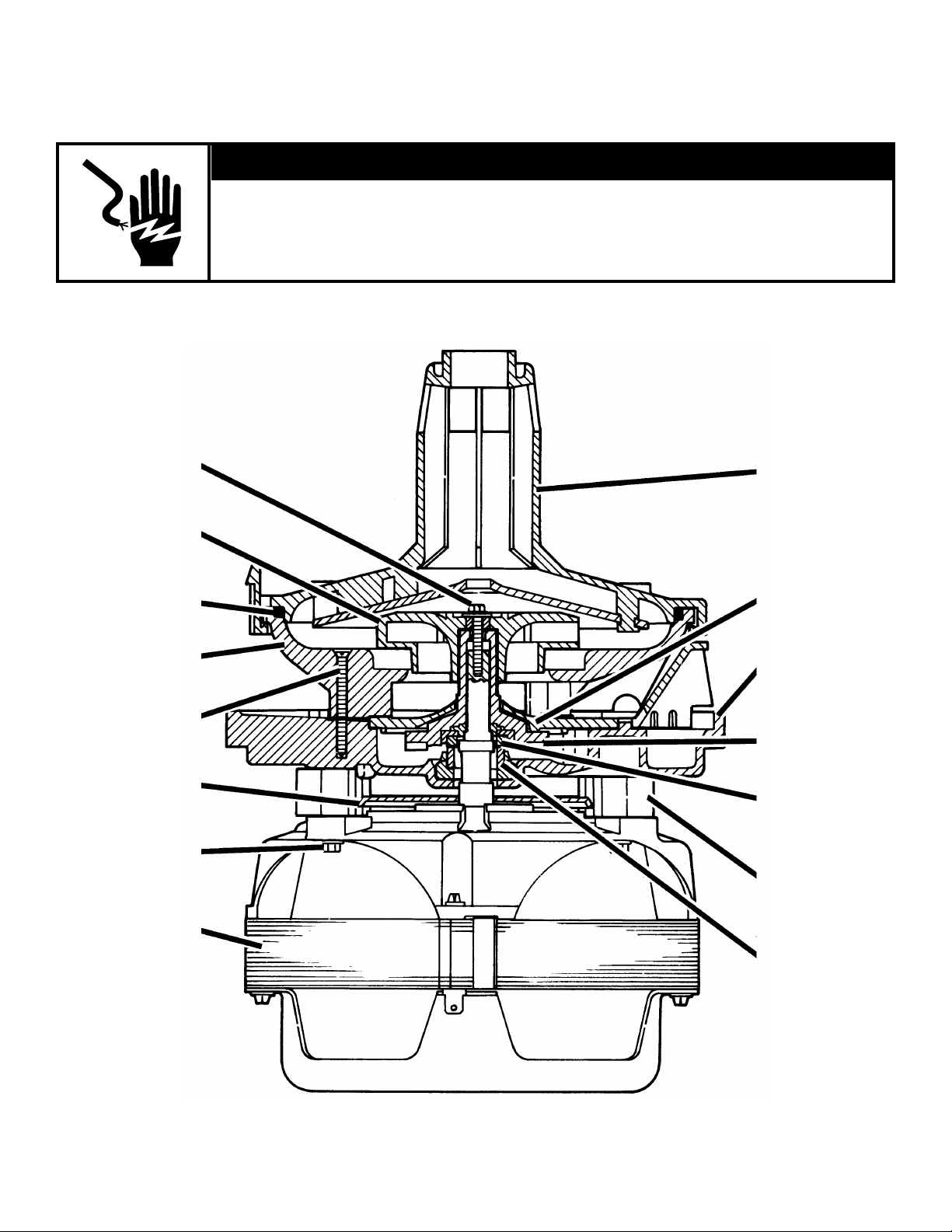
Impeller mounting
screw
Wash impeller
Pump seal
Lower pump housing
Lower pump
housing screw (3)
Slinger
Pump mounting
plate screw (4)
pump housing
Upper
Drain cover
Pump
mounting
plate
Drain impeller
Ceramic seal
Pump
mounting
extensions (4)
Motor
© Whirlpool Corporation 1997
(All Rights Reserved)
Carbon
face seal
Cutaway view – Whirlpool pump and motor assembly
Instruction Sheet 675475 Rev. A 8/97
1
Disassembly:
1. Disconnect power or unplug dishwasher.
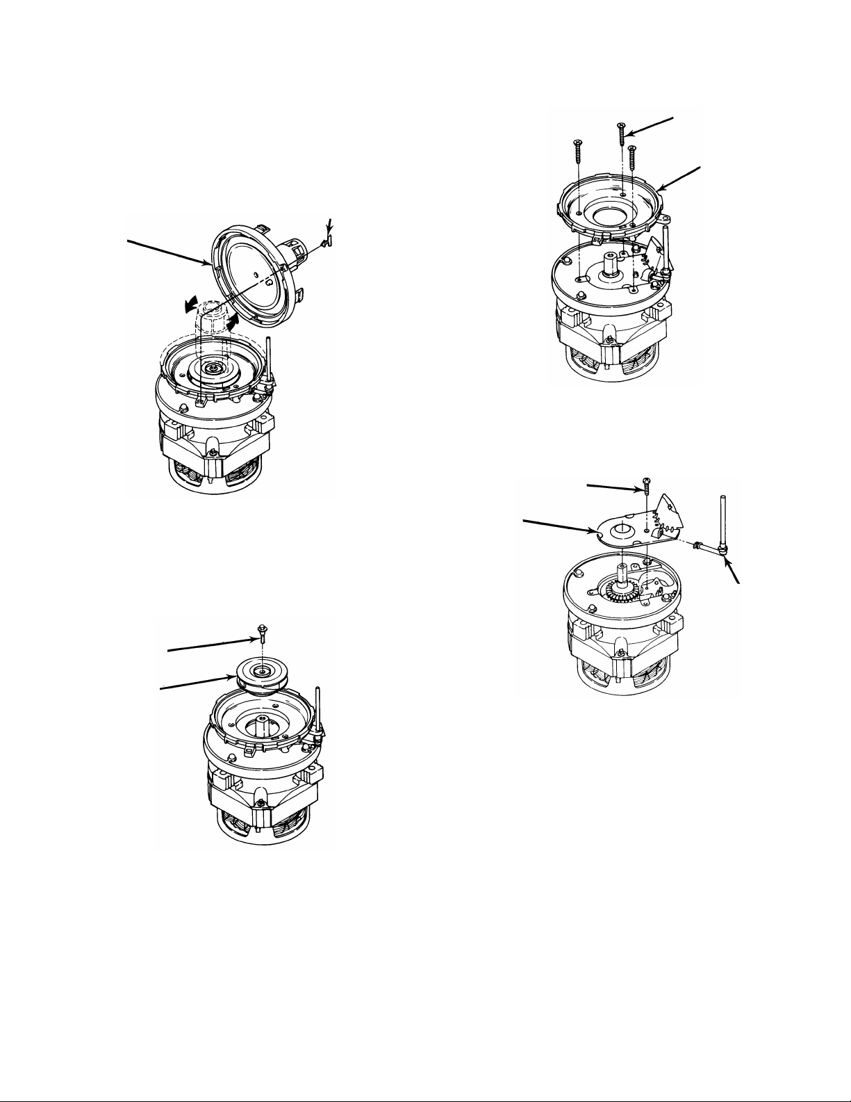
2. Remove blue locking tab, then rotate upper pump
housing counterclockwise and lift out of locating slots.
See Figure 1.
NOTE: Some early production pumps utilized a plastic tie to prevent rotation of upper pump housing. Tie
must be cut before upper housing can be removed.
Blue
Upper
pump
housing
Figure 1
locking tab
4. Using a Phillips head screwdriver, remove three
(3) screws which secure lower pump housing to
pump mounting plate. Lower pump housing can
now be removed. See Figure 3.
(3) Pump housing
screws
Lower pump
housing
Figure 3
5. Remove screw which secures drain pump cover to
pump mounting plate, and remove drain pump cover
and air bleed standpipe assembly. See Figure 4.
Phillips head screw
Drain pump
cover
3. To remove the impeller mounting screw, use 5⁄16"
nutdriver. Impeller mounting screw has right-hand
thread. If mounting screw is hard to back out, redrive
to tighten, then back out. Lift wash impeller off shaft.
See Figure 2.
Impeller
mounting
screw
Wash impeller
Figure 2
Drain air
bleed
standpipe
Figure 4
(continued)
675475-A
2
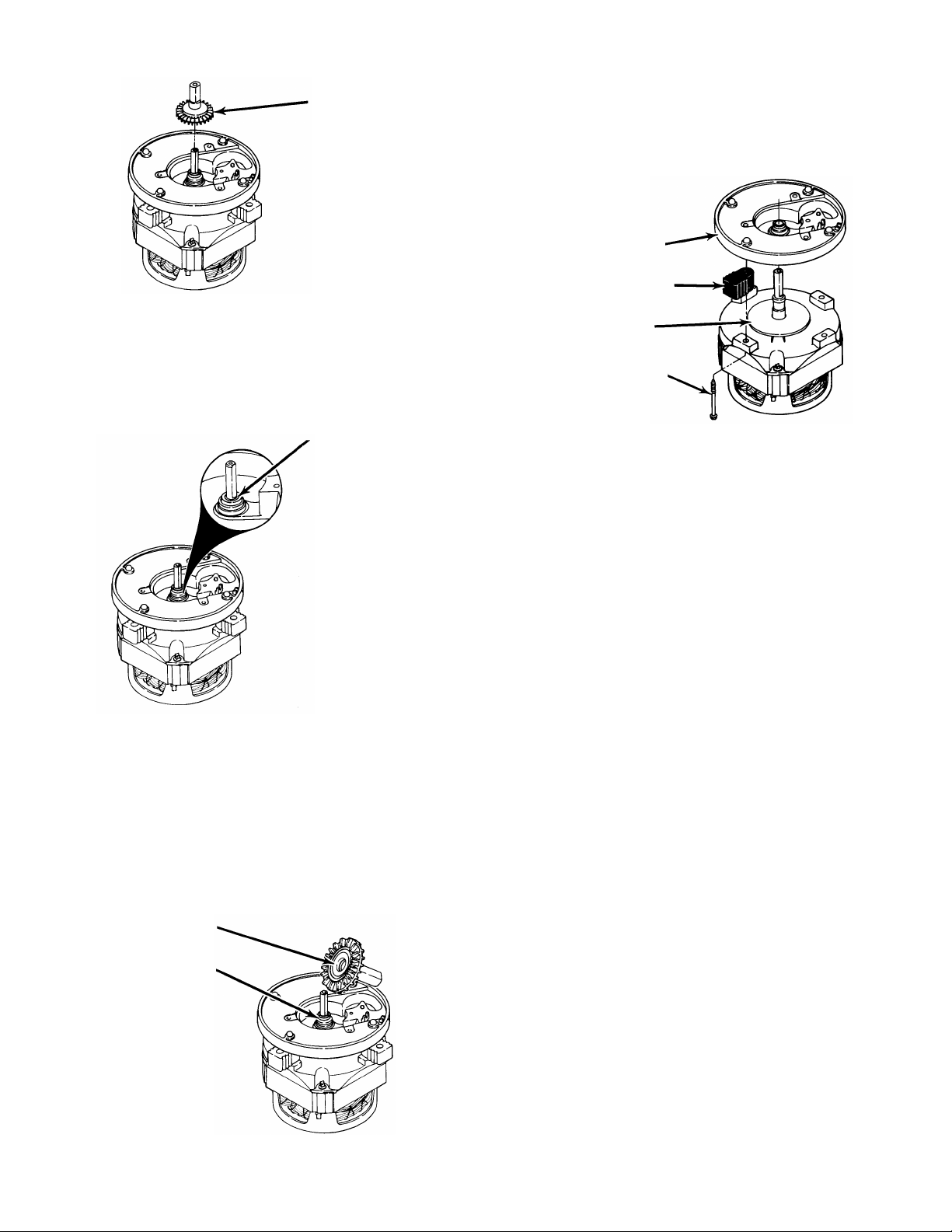
6. Remove drain impeller by pulling it straight up off the
shaft. See Figure 5.
Drain
impeller
Figure 5
7. There may or may not be drain impeller shim(s)
on motor shaft. See Figure 6. Shim washer(s) are
designed to compensate for variations in tolerance
and do not appear in parts lists. Do not remove
shims. If motor is replaced, shims will be on new
replacement motor if required.
Motor shim(s)
Figure 6
8. Both halves of seal assembly are now visible. This
assembly consists of a stationary half and a half
that revolves. The stationary half has a carbon
face attached to a rubber, spring-loaded body. See
Figure 7. The movable half is a ceramic ring seated in
a rubber bushing. Both can be easily pried out of
location with a small screwdriver.
IMPORTANT: When rebuilding pump, always replace
both seal halves and drain impeller.
Ceramic seal half
9. Using the 1⁄4" nutdriver, remove four (4) screws which
secure pump mounting plate to motor, and lift pump
mounting plate off motor. See Figure 8.
10. Rubber pump mounting extensions can be removed
from pump mounting plate. See Figure 8.
11. If motor is to be replaced, slinger can now be
removed. See Figure 8.
Pump mounting plate
Mounting extension
Large slinger
(4) Screws
Figure 8
Reassembly:
1. Before you begin, check motor for the following:
a. Rotor shaft end play – Maximum is .010".
b. Rotor rotation – Should rotate freely.
c. Top mount bearing – If there is evidence of water
having entered area, add a few drops of SAE
No. 20 non-detergent motor oil to reservoir.
d. Electrical open, shorted or grounded winding
(See check procedure page 3-50 of Dishwasher
Service Manual 828837).
2. Install slinger by pressing it onto motor shaft so that it
bottoms out.
3. With trichloroethane (or equivalent), clean out carbon
face seal seat area of pump mounting plate.
4. Slip four (4) rubber mounting extensions onto pump
mounting plate.
5. With motor positioned so electrical connector is facing
front, position pump mounting plate on motor so drain
outlet is facing right side. Drive four (4) screws which
secure pump mounting plate to motor, but do not
completely tighten.
Carbon face seal
675475-A
Figure 7
(continued)
3
 Loading...