

Whirlpool 3LWED4705FW0, 4KMEDC425FW0, 4KMEDC315FW0, 4KMEDC215FW0, 3LWED4815FW0 Installation Guide
Page 1
DRYER INSTALLATION INSTRUCTIONS
737 mm (29") Wide Models – Gas & Electric
INSTRUCTIONS D’INSTALLATION DU SECHE-LINGE
Modèles de 737 mm (29") de largeur – À gaz et Électrique
INSTRUCCIONES DE INSTALACIÓN DE LA SECADORA
Modelos de 737 mm (29") – A gas y eléctrica
ISTRUZIONI DI INSTALLAZIONE DELL’ASCIUGATRICE
Modelli da 737 mm (29") – A gas ed elettrici
TROCKNER – INSTALLATIONSANWEISUNGEN
737 mm (29 Zoll) breite Modelle – Gas und Elektro
TABLE OF CONTENTS (Original Instructions)
DRYER SAFETY ........................................................................................ 2
SPECIFICATIONS ......................................................................................4
INSTALLATION REQUIREMENTS ............................................................ 5
ELECTRIC DRYER POWER HOOKUP ..................................................... 7
INSTALL LEVELING LEGS ........................................................................8
GAS DRYER POWER HOOKUP ............................................................... 8
ELECTRICAL REQUIREMENTS ............................................................. 10
ELECTRICAL CONNECTION ................................................................. 10
VENTING .................................................................................................. 13
MAKE GAS CONNECTION ..................................................................... 16
CONNECT VENT ..................................................................................... 17
LEVEL DRYER ......................................................................................... 17
POWER CORD INSTALLATION ..............................................................18
COMPLETE INSTALLATION CHECKLIST ............................................. 18
REVERSE DOOR SWING (OPTIONAL) .................................................. 19
TROUBLESHOOTING ............................................................................. 21
SÉCURITÉ DU SECHE-LINGE ............................................................... 22
TABLE DES MATIÈRES (Instructions d’origine)
CARACTERISTIQUES ............................................................................. 24
EXIGENCES D’INSTALLATION ..............................................................25
RACCORDEMENT À L’ALIMENTATION ÉLECTRIQUE
DU SECHE-LINGE ÉLECTRIQUE ........................................................... 28
INSTALLATION DES PIEDS DE NIVELLEMENT ...................................29
RACCORDEMENT D’UN SECHE-LINGE À GAZ ................................... 29
SPÉCIFICATIONS ÉLECTRIQUES ..........................................................31
RACCORDEMENT ÉLECTRIQUE ........................................................... 31
ÍNDICE (Instrucciones originales)
SEGURIDAD DE LA SECADORA ........................................................... 44
ESPECIFICACIONES .............................................................................. 46
REQUISITOS DE INSTALACIÓN ............................................................ 47
CONEXIÓN DE ENERGÍA DE LA SECADORA ÉLECTRICA ................. 50
INSTALACIÓN DE LAS PATAS NIVELADORAS..................................... 51
CONEXIÓN DE ENERGÍA DE LA SECADORA A GAS .......................... 52
REQUISITOS ELÉCTRICOS ................................................................... 53
CONEXIÓN ÉLECTRICA ......................................................................... 54
VENTILACIÓN ......................................................................................... 57
SOMMARIO (Istruzioni originali)
SICUREZZA DELL’ASCIUGATRICE ....................................................... 67
SPECIFICHE ............................................................................................ 69
REQUISITI PER L’INSTALLAZIONE ....................................................... 70
ALLACCIAMENTO DELL’ASCIUGATRICE ELETTRICA
ALL’ALIMENTAZIONE ............................................................................72
INSTALLAZIONE DEI PIEDINI DI MESSA IN PIANO ............................73
ALLACCIAMENTO DELL’ASCIUGATRICE A GAS
ALL’ALIMENTAZIONE .............................................................................73
REQUISITI ELETTRICI ............................................................................ 75
L’ÉVACUATION........................................................................................ 34
RACCORDEMENT AU GAZ .................................................................... 38
RACCORDEMENT DU CONDUIT D’ÉVACUATION .............................. 38
RÉGLAGE DE L’APLOMB DU SECHE-LINGE ....................................... 39
INSTALLATION DU CORDON D’ALIMENTATION ................................. 39
ACHEVER L’INSTALLATION – LISTE DE VÉRIFICATION ..................... 40
INVERSION DU SENS DE L’OUVERTURE
DE LA PORTE
DÉPANNAGE ........................................................................................... 43
CONEXIÓN DEL SUMINISTRO DE GAS................................................ 60
CONEXIÓN DEL DUCTO DE ESCAPE................................................... 61
NIVELACIÓN DE LA SECADORA........................................................... 61
INSTALACIÓN DEL CABLE ELÉCTRICO .............................................. 62
LISTA DE CONTROL DE LA INSTALACIÓN TERMINADA ................... 63
CAMBIO DEL SENTIDO DE ABERTURA
DE LA PUERTA (OPCIONAL).................................................................. 63
SOLUCIÓN DE PROBLEMAS ................................................................. 66
COLLEGAMENTO ELETTRICO .............................................................. 75
SISTEMA DI SFIATO ............................................................................... 78
COLLEGAMENTO ALL’IMPIANTO A GAS .............................................81
COLLEGAMENTO ALLO SFIATO ........................................................... 82
MESSA IN PIANO DELL’ASCIUGATRICE .............................................. 82
INSTALLAZIONE DEL CAVO DI ALIMENTAZIONE ............................... 83
COMPILAZIONE DELLA CHECKLIST DI INSTALLAZIONE ................. 83
INVERSIONE DELL’APERTURA DELLO SPORTELLO (OPZIONALE)
RISOLUZIONE DEI PROBLEMI .............................................................. 86
(FACULTATIF)
.................................................................. 41
................ 84
INHALTSVERZEICHNIS (Originalanweisungen)
SICHERHEIT DES TROCKNERS............................................................ 87
SPEZIFIKATIONEN .................................................................................89
INSTALLATIONSANFORDERUNGEN .................................................... 90
ELEKTROTROCKNER – ELEKTRISCHER ANSCHLUSS ..................... 92
STELLFÜSSE INSTALLIEREN ................................................................ 93
GASTROCKNER – ELEKTRISCHER ANSCHLUSS ............................... 93
ELEKTRISCHE ANFORDERUNGEN ...................................................... 95
ELEKTRISCHER ANSCHLUSS .............................................................. 95
W10849532D
ENTLÜFTUNGSSYSTEM ........................................................................ 98
GASANSCHLUSS HERSTELLEN ......................................................... 101
ENTLÜFTUNGS ANSCHLIESSEN ........................................................ 102
TROCKNER NIVELLIEREN................................................................... 102
INSTALLATION DES NETZKABELS .....................................................103
KOMPLETTE INSTALLATIONS-CHECKLISTE .................................... 103
TÜRANSCHLAG WECHSELN (OPTIONAL) ......................................... 104
FEHLERBEHEBUNG ............................................................................. 106
Page 2

DRYER SAFETY
CAUTION – RISK OF FIRE/FLAMMABLE MATERIALS
This is an additional safety alert symbol that alerts you to the risk of re.
2
Page 3
FOR YOUR SAFETY
Before the dryer is removed from service or discarded,
1. DO NOT USE OR STORE PETROL OR OTHER FLAMMABLE MATERIALS IN THIS APPLIANCE OR
NEAR THIS APPLIANCE.
2. DO NOT SPRAY AEROSOLS IN THE VICINITY OF THIS APPLIANCE WHILE IT IS IN OPERATION.
3. DO NOT MODIFY THIS APPLIANCE.
IMPORTANT SAFETY INSTRUCTIONS
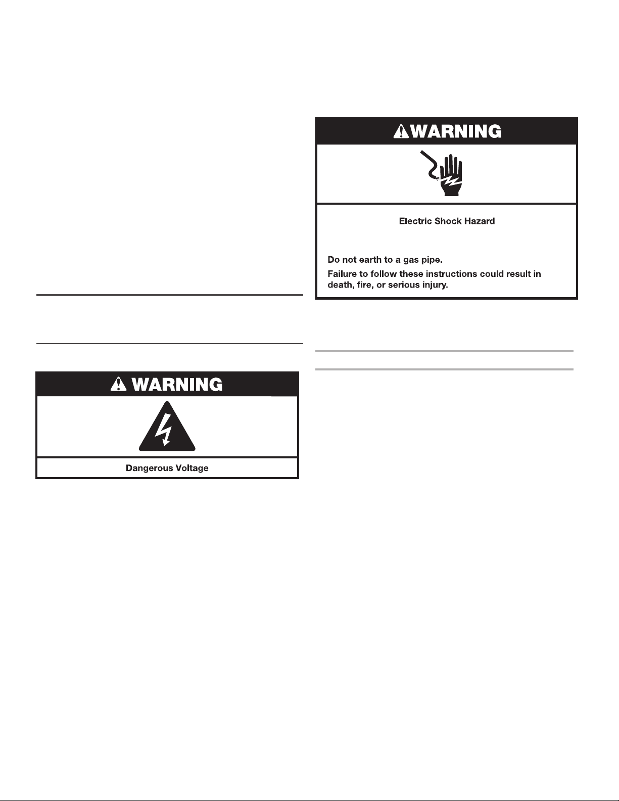
WARNING: To reduce the risk of re, electric shock, or injury to persons when using the dryer, follow basic precautions,
including the following:
n
n Read all instructions before using the dryer.
n Keep a minimum clearance of 100 mm (4 in.) between
the rear of the dryer and any wall.
n The operation of this appliance may affect the operation
of other types of appliances which take their air supply
for safe combustion from the same room. There has to
be adequate ventilation to replace exhausted air and
thus avoid the back-ow of gases into the room from
appliances burning other fuels, including open res,
when operating the tumble dryer. If in doubt, consult
the appliance manufacturers.
n Do not obstruct the air supply to the dryer (see
Installation Instructions for minimum clearances).
n Do not place items exposed to cooking oils in your dryer.
Oil-affected items can ignite spontaneously, especially
when exposed to heat sources such as in a tumble dryer.
The items become warm causing an oxidation reaction in
the oil. Oxidation creates heat. If the heat cannot escape,
the items can become hot enough to catch re. Piling,
stacking or storing oil-affected items can prevent heat
from escaping and so create a re hazard.
n If it is unavoidable to dry in the dryer items that have
been soiled with substances such as cooking oil,
acetone, alcohol, petrol, kerosene, spot removers,
turpentine, waxes and wax removers, or that have
been contaminated by hair care products, they should be
washed in hot water with an extra amount of detergent
before being dried in the dryer. These items may give off
vapours that could ignite or explode. Such washing will
reduce, but not eliminate, the hazard.
n This appliance is not intended for use by persons
(including children under 8 years of age) with reduced
physical, sensory or mental capabilities, or lack of
experience and knowledge, unless they have been
given supervision or instructions concerning use of
the appliance by persons responsible for their safety.
n Cleaning and user maintenance by children must be
supervised.
n Children should be supervised to ensure that they do not
play with the appliance.
n Children less than 3 years of age should be kept away
from the appliance unless continuously supervised.
n The dryer should not be used if industrial chemicals have
been used for cleaning.
Remove all objects from pockets, such as lighters and
matches, before placing items in the dryer.
n Before the dryer is removed from service or discarded,
remove the doors to the drying compartment.
n Do not reach into the dryer if the drum is moving.
A door switch is tted for your safety.
n Do not install or store the dryer where it will be exposed
to the weather.
n Do not tamper with controls.
n Do not continue to use this appliance if it appears
to be faulty.
n Do not repair or replace any part of the dryer or attempt
any maintenance unless specically recommended in the
Use and Care Guide. Repairs and servicing should only
be carried out by competent service personnel.
n Do not use fabric softeners or products to eliminate static
unless recommended by the manufacturer of the fabric
softener or product. Follow their instructions.
n Clean dryer lint screen before or after each load.
Do not operate dryer without lint screen in place.
n Keep area around the exhaust and inlet openings and
adjacent surrounding areas free from the accumulation
of lint, dust, and dirt.
n The interior of the dryer and exhaust vent should be
cleaned periodically by qualied service personnel.
n See “Electrical Requirements” for earthing instructions.
n Do not dry unwashed items in this dryer.
n The nal part of a tumble dryer cycle occurs without heat
(cool down cycle) to ensure that the items are left at a
temperature that ensures the items will not be damaged.
n Items such as foam rubber (latex foam), shower caps,
waterproof textiles, rubber backed articles, and clothes
or pillows tted with foam rubber pads must only be dried
on a clothesline.
n If the supply cord is damaged, it must be replaced by the
manufacturer or its service agent or a similarly qualied
person in order to avoid a hazard.
WARNING: Never stop a tumble dryer cycle before the
end of the drying cycle unless all items are quickly removed
and spread out so that the heat is dissipated.
SAVE THESE INSTRUCTIONS
3
Page 4
This appliance is marked according to the European directive 2012/19/EU on Waste Electrical and Electronic Equipment
(WEEE).
By ensuring this product is disposed of correctly, you will help avoid potential negative consequences for the environment
and human health, which could otherwise be caused by inappropriate waste handling of this product.
The symbol on the product, or on the documents accompanying the product, indicates that this appliance may not be
treated as household waste. Instead it shall be handed over to the applicable collection point for the recycling of electrical
and electronic equipment.
Disposal must be carried out in accordance with local environmental regulations for waste disposal.
For more detailed information about treatment, recovery and recycling of this product, please contact your local city ofce,
your household waste disposal service or the shop where you purchased the product.
SPECIFICATIONS
These units are sold in multiple regions with different
requirements for measuring capacity. Below are a few
of the valid forms of measure posted on this product:
Dry Linen Capacity: A weight measure that reects
a maximum load size that can be loaded into the dryer.
IEC Capacity: The capacity measure that represents the
maximum capacity of dry linens and textiles which the
manufacturer declares can be treated in a specic cycle.
Dry Linen Capacity
15 kg (33 lb)
IEC Capacity
7 kg (15 lb)
4
Page 5

INSTALLATION REQUIREMENTS
Tools and Parts
Gather the required tools and parts before starting installation.
Tools needed for all installations:
Tools needed for gas installations:
Flat-blade screwdriver
6 mm (1/4") nut driver
or socket wrench
(recommended)
Tape measure
Level
#2 Phillips screwdriver
Tin snips (new vent
installations)
Vent clamps
Pliers
203 mm or 254 mm
(8" or 10") pipe wrench
Pipe-joint compound
resistant to propane gas
203 mm or 254 mm
(8" or 10") adjustable wrench
(for gas connections)
Parts supplied:
Leveling legs (4)
Parts package is located in dryer drum. Check that all parts
are included.
Plugs and cord lock cover
(supplied with some
models only)
Parts needed:
Check local codes. Check existing electrical supply and venting.
See “Electrical Requirements” and “Venting Requirements”
before purchasing parts.
Check code requirements. Some codes limit, or do not permit,
installing dryer in garages, closets, mobile homes, or sleeping
quarters. Contact your local building inspector.
Optional Equipment: (Not supplied with dryer)
Refer to your Use and Care Guide for information about
accessories available for your dryer.
Adjustable wrench that
opens to 25 mm (1") or
hex-head socket wrench
Utility knife
Caulking gun and
compound (for installing
new exhaust vent)
Putty knife
5
Page 6
Location Requirements
29"
29"
3"*
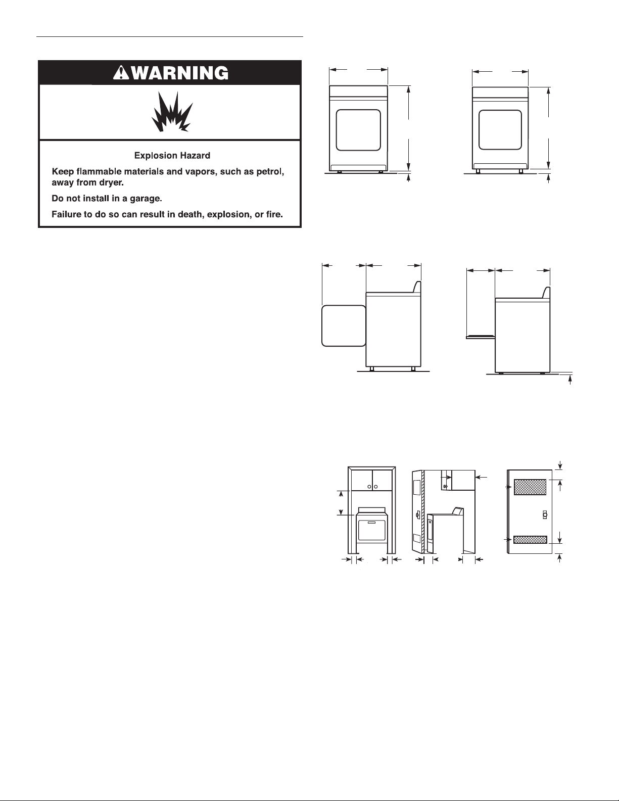
Dryer Dimensions
737 mm
(29")
(737 mm)
737 mm
(29")
(737 mm)
You will need:
n A location allowing for proper exhaust installation.
See “Venting Requirements.”
n A separate 30-amp circuit for electric dryers.
n A separate 15- or 20-amp circuit for gas dryers.
n If you are using power supply cord, a earthed electrical outlet
located within 610 mm (2 ft.) of either side of dryer.
See “Electrical Requirements.”
n A sturdy oor to support dryer and a total weight
(dryer and load) of 90.7 kg. (200 lbs). The combined weight
of a companion appliance should also be considered.
n Level oor with maximum slope of 25 mm (1") under entire
dryer. If slope is greater than 25 mm (1"), install Extended
Dryer Feet Kit, Part Number 279810. If not level, clothes
may not tumble properly and automatic sensor cycles
may not operate correctly.
Do not operate your dryer at temperatures below 7°C (45°F).
At lower temperatures, the dryer might not shut off at the end
of an automatic cycle. Drying times can be extended.
The dryer must not be installed or stored in an area where
it will be exposed to water and/or weather.
Check code requirements. Some codes limit, or do not permit,
installation of the dryer in garages, closets, mobile homes,
or sleeping quarters. Contact your local building inspector.
NOTE: No other fuel-burning appliance can be installed
in the same closet as a dryer.
Installation clearances:
The location must be large enough to allow the dryer door
to open fully.
Do not install behind a lockable door, a sliding door, or a door
with a hinge on the side opposite to that of the dryer in a way
that will restrict the full opening of the dryer door.
Most installations require a minimum 140 mm (5½") clearance
behind the dryer for the exhaust vent with elbow. See “Venting
Requirements.”
1102 mm
433/8"
(433⁄8")
(1102 mm)
1
/2"
13 mm
(13 mm)
(1⁄2")
1102 mm
433/8"
(433⁄8")
(1102 mm)
11/2"
38 mm
(38 mm)
(11⁄2")
NOTE: Leveling legs should be 13 mm (1/2") (to match height
of 0.102 m3 [3.6 cu. ft.] capacity washer) or 38 mm (1½")
(to match height of 0.108 m3 [3.8 cu. ft.] capacity washer).
349 mm
578 mm
223/4"
(223⁄4")
(578 mm)
705 mm
273/4"
(273⁄4")
(705 mm)
133/4"
(133⁄4")
(349 mm)
705 mm
273/4"
(273⁄4")
(705 mm)
A B
A. Wide-opening side-swing door
B. Wide-opening hamper door
Installation Spacing
18"*
457 mm*
(457 mm)
(18")
737 mm
1"
(25 mm)
29"
1"
(29")
(737 mm)
25 mm
(1")
(25 mm)
25 mm
(1")
A B
A. Recessed area
B. Side view—closet or conned area
C. Closet door with vents
705 mm
1"*
25 mm*
(25 mm)
(1")
356 mm*
14" max.*
(14" max.)
(356 mm)
(273⁄4")
27¾"
140 mm
(705 mm)
(51⁄2")
2
48 in.
*
310 cm2*
(310 cm )
(48 in.2)
2
155 cm2*
*
24 in.
(24 in.2)
(155 cm )
2
2
76 mm*
76 mm*
C
*Required spacing
13 mm
(1⁄2")
(3")
(76 mm)
3"*
(76 mm)
(3")
6
Page 7
Installation spacing for recessed area or closet
The dimensions shown are for the minimum spacing allowed.
n Additional spacing should be considered for ease of
installation and servicing.
n Additional clearances might be required for wall, door,
and oor moldings.
n Additional spacing of 25 mm (1") on all sides of the dryer
is recommended to reduce noise transfer.
n For closet installation, with a door, minimum ventilation
openings in the top and bottom of the door are required.
Louvered doors with equivalent ventilation openings are
acceptable.
n Companion appliance spacing should also be considered.
Mobile home – Additional installation requirements
This dryer is suitable for mobile home installations. The
installation must conform with local codes and ordinances.
n Metal exhaust system hardware, available for purchase.
n Special provisions must be made in mobile homes to
introduce outside air into the dryer. The opening (such
as a nearby window) should be at least twice as large
as the dryer exhaust opening.
NOTE: In accordance with the European EMC Directive
(2014/30/EU), the maximum electricity supply system impedance
to which the electric dryer should be connected is declared
to be 0.191 + j0.119 Ohms.
NOTE: Electrical safety standards: The manufacturer has
chosen compliance with IEC/EN.60335 standards as the most
appropriate for this product.
This is 3-wire appliance which must be earthed.
ELECTRIC DRYER
POWER HOOKUP
Electrical Requirements
This dryer is supplied without an electric cord and plug.
It must be connected by a competent electrician to a singlephase electricity supply at the voltage shown on the dataplate,
using a suitable xed wiring installation in accordance with local
and national wiring regulations.
n A 3-wire circular cord of minimum conductor size 4 mm2
cross-section area should be used.
n A 30A supply fuse should be used, and a switch having
a contact separation in both poles that provides full
disconnection under over-voltage category III conditions
must be incorporated into the xed wiring in accordance
with local wiring regulations. The dryer should be positioned
so that the disconnection switch is clearly visible and easily
accessible to the user. This disconnection switch also
provides the function of an emergency stop control
for the user.
n A cord clamp bush is provided on the dryer and should
be tightened on completion of wiring. The electrical mains
terminals are located behind the small rear access panel
(terminal block cover), and connections should be made
in accordance with the terminal markings. Remember to
replace the terminal access panel (terminal block cover).
If codes permit and an additional earth bond wire is used,
it is recommended that a qualied electrician determine that
the earth bond path is adequate.
Recommended earthing method
It is your responsibility to contact a qualied electrical installer
to ensure that the electrical installation is adequate and in
conformance with all local codes and ordinances.
7
Page 8
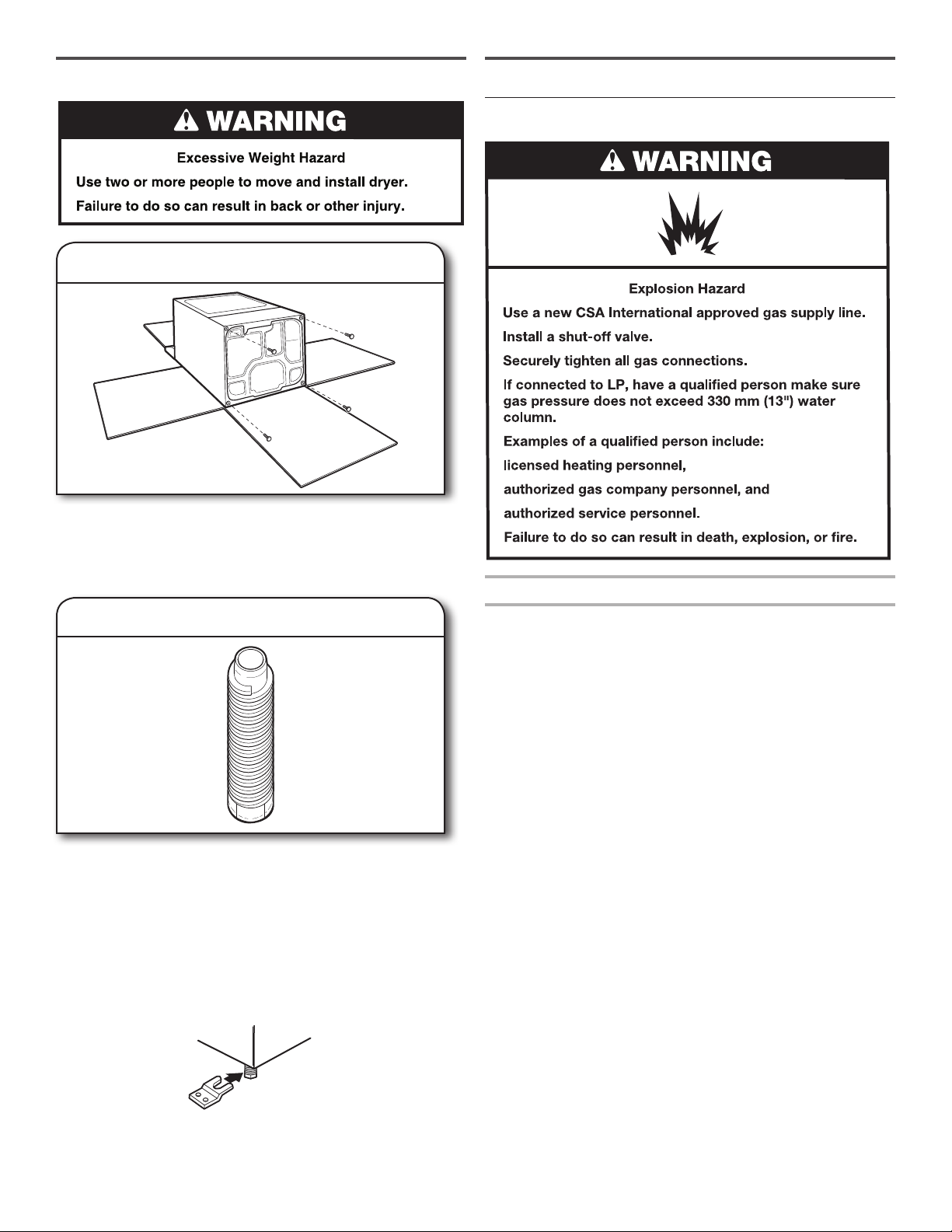
INSTALL LEVELING LEGS
1. Prepare dryer for leveling legs
To avoid damaging oor, use a large at piece of cardboard
from dryer carton; place under entire back edge of dryer.
Firmly grasp dryer body (not console panel) and gently lay
dryer down on cardboard.
GAS DRYER POWER HOOKUP
Gas Supply Requirements
2. Screw in leveling legs
Using a wrench and tape measure, screw legs into leg
holes until bottom of foot is approximately 13 mm (1/2")
(to match height of 0.102 m3 [3.6 cu. ft.] capacity washer) or
38 mm (1½") (to match height of 0.108 m3 [3.8 cu. ft.] capacity
washer) from bottom of dryer.
Now stand the dryer on its legs. Slide the dryer until it is
close to its nal location. Leave enough room for electrical
connection and to connect the exhaust vent.
For mobile home use
Gas dryers must be securely fastened to the oor.
Gas type
Natural gas:
This dryer is equipped for use with Natural Gas. It is designcertied by CSA International for propane or butane gases with
appropriate conversion.
n Your dryer must have the correct burner for the type of gas
in your home. Burner information is located on the rating
plate in the door well of your dryer.
Propane gas conversion:
Conversion must be made by a qualied technician.
No attempt shall be made to convert the dryer from the gas
specied on the model/serial rating plate for use with a different
gas without consulting the serving gas supplier.
IMPORTANT: The gas installation must conform with local codes.
Mobile home installations require a Mobile Home Installation
Hold-down Kit. For ordering information, please reference
the Use and Care Guide.
8
Page 9
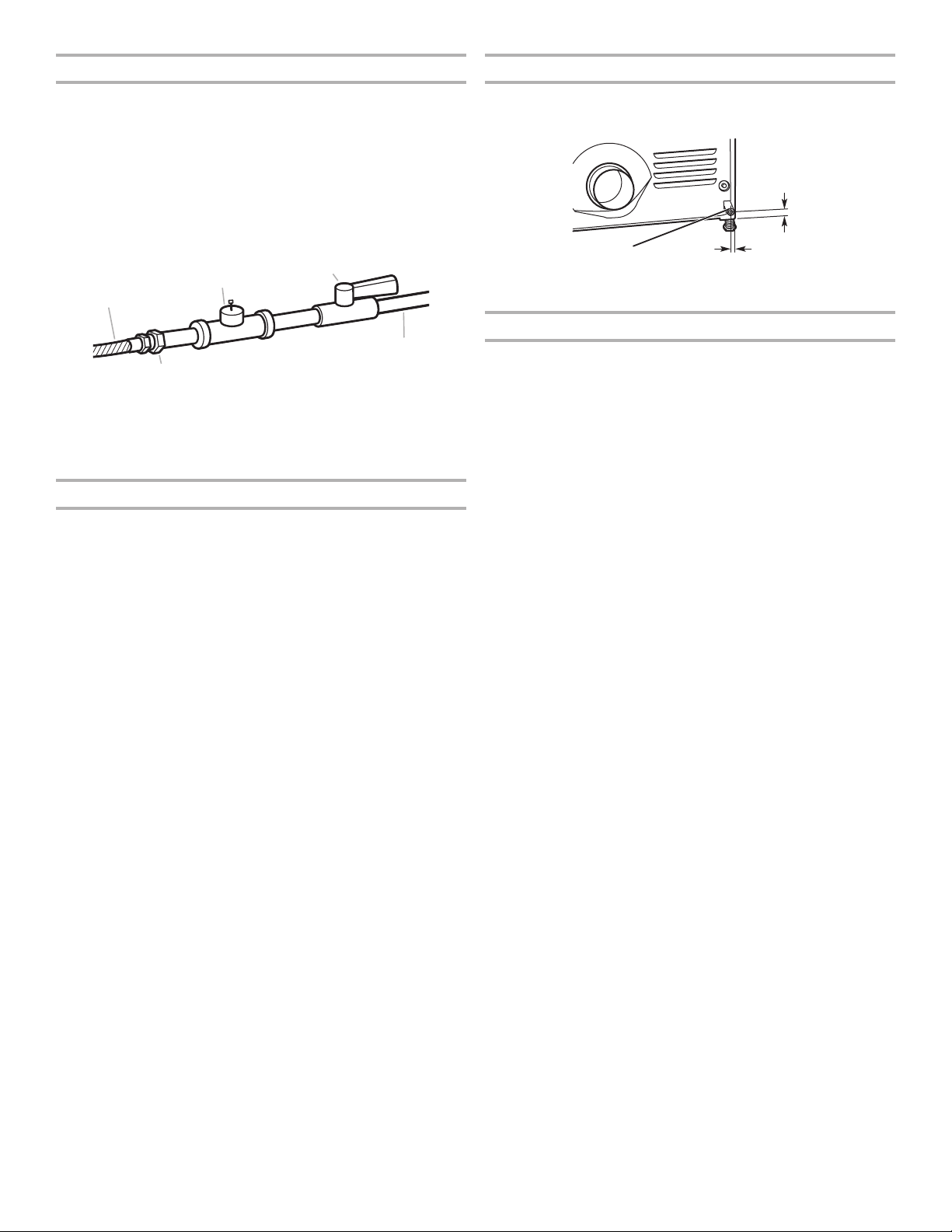
Gas supply line
Dryer gas pipe
n 13 mm (1/2") NPT pipe is recommended.
n 9.5 mm (3/8") approved tubing is acceptable for lengths
under 6.1 m (20 ft.) if local codes and gas supplier permit.
n Must include 3.2 mm (1/8") NPT minimum plugged tapping
accessible for test gauge connection, immediately upstream
of the gas connection to the dryer (see illustration).
n Must include a shut-off valve.
The shut-off valve location should be easy to reach for opening
and closing.
E
C
A
D
B
A. 9.5 mm (3/8") exible gas connector
B. 9.5 mm (3/8") pipe to are adapter tting
C. 3.2 mm (1/8") NPT minimum plugged tapping
D. 13 mm (1/2") NPT gas supply line
E. Gas shut-off valve
Gas supply connection requirements
There are many methods by which your gas dryer can be
connected to the gas supply. Listed here are some guidelines
for two different methods of connection.
This dryer must be connected to the gas supply line with
a listed exible gas connector that complies with the standard
for connectors for gas appliances, CSA 6.10.
Option 1 (Recommended Method)
Flexible stainless steel gas connector:
n If local codes permit, use a new exible stainless steel gas
connector (Design Certied by CSA International) to connect
your dryer to the rigid gas supply line. Use an elbow and
a 9.5 mm (3/8") are x 9.5 mm (3/8") NPT adapter tting
between the stainless steel gas connector and the dryer
gas pipe, as needed, to prevent kinking.
Option 2 (Alternate Method)
Approved aluminum or copper tubing:
n Lengths over 6.1 m (20 ft.) can use 9.5 mm (3/8") approved
tubing (if codes and gas supplier permit).
n If you are using Natural Gas, do not use copper tubing.
n 9.5 mm (3/8") are x 9.5 mm (3/8") NPT adapter tting
between dryer pipe and 9.5 mm (3/8") approved tubing.
n Lengths over 6.1 m (20 ft.) should use larger tubing and
a different size adapter tting.
n If your dryer has been converted to use propane gas, 9.5 mm
(3/8") propane compatible copper tubing can be used. If the
total length of the supply line is more than 6.1 m (20 ft.), use
larger pipe.
NOTE: Pipe joint compounds that resist the action of
propane gas must be used. Do not use TEFLON®† tape.
n The gas pipe that comes out through the rear of your dryer
has a 9.5 mm (3/8") male pipe thread.
1¼"
(32 mm)
32 mm
(11⁄4")
A
A. 9.5 mm (3/8") NPT dryer pipe
9¼"
235 mm
(235 mm)
(91⁄4")
Burner input requirements
Elevations up to 3,048 m (10,000 ft.):
n The design of this dryer is certied by CSA International for
use at altitudes up to 3,048 m (10,000 ft.) above sea level at
the BTU rating indicated on the model/serial number plate.
Burner input adjustments are not required when the dryer is
operated up to this elevation.
Elevations above 3,048 m (10,000 ft.):
n When installed above 3,048 m (10,000 ft.), a 4% reduction
of the burner BTU rating shown on the model/serial
number plate is required for each 305 m (1,000 ft.)
increase in elevation.
Gas supply pressure testing
n The dryer must be disconnected from the gas supply piping
system during pressure testing at pressures greater than
352 kg/m2 (1/2 psi).
†®TEFLON is a registered trademark of Chemours.
9
Page 10
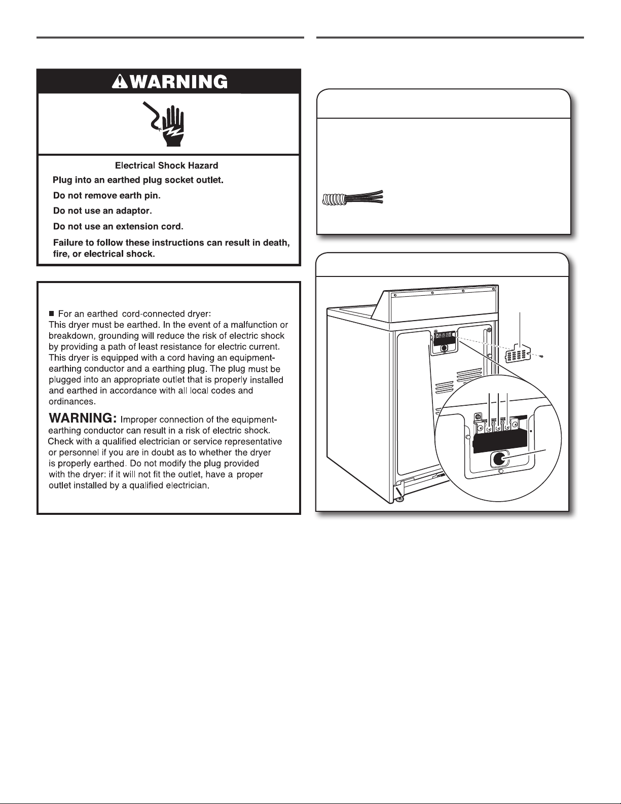
ELECTRICAL REQUIREMENTS
EARTHING INSTRUCTIONS
ELECTRICAL CONNECTION
Electrical Connection Options
1. Choose electrical connection type
Power supply cord: Go to steps 1–2 on
page 11 for power supply cord strain relief,
then steps 3–5 in “Power Supply Cord
Connection” section. Then go to “Venting
Requirements.”
Direct wire connection: Go to steps 1–2
on page 11 for direct wire strain relief, then
steps 3–7 in “Direct Wire Connection”
section. Then go to “Venting Requirements.”
2. Remove terminal block cover
A
SAVE THESE INSTRUCTIONS
BCD
E
Before you start, disconnect power. Remove terminal block
cover (A).
A. Terminal block cover
B. Active screw
C. Ground screw
D. Neutral screw
E. Strain relief hole
10
Page 11
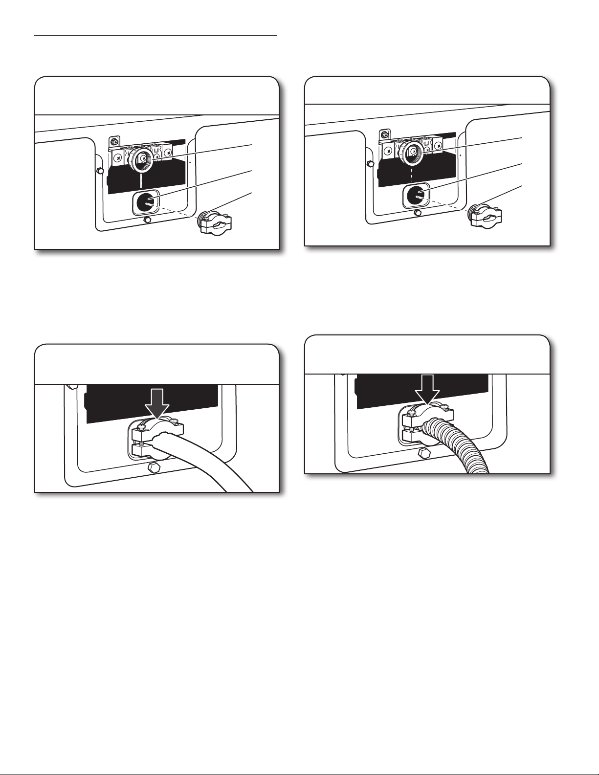
Install Strain Relief
Power supply cord strain relief
Direct wire strain relief
1. Attach power supply cord
strain relief
A
B
C
Unscrew the removable conduit connector (A) and any
screws from a 19 mm (3/4") strain relief. Put the threaded
section of the strain relief through the hole (B) below the
terminal block opening. Reaching inside the terminal block
opening, screw the removable conduit connector onto the
strain relief threads (C).
2. Attach power supply cord
to strain relief
1. Attach direct wire strain relief
A
B
C
Unscrew the removable conduit connector (A) and any
screws from a 19 mm (3/4") strain relief. Put the threaded
section of the strain relief through the hole (B) below the
terminal block opening. Reaching inside the terminal block
opening, screw the removable conduit connector onto the
strain relief threads (C).
2. Attach direct wire cable
to strain relief
Put power supply cord through the strain relief. Be sure that
the wire insulation on the power supply cord is inside the
strain relief. The strain relief should have a tight t with the
dryer cabinet and be in a horizontal position. Do not further
tighten strain relief screws at this point.
Go to “Power Supply Cord Connection.”
Put direct wire cable through the strain relief. The strain relief
should have a tight t with the dryer cabinet and be in a
horizontal position. Securely tighten strain relief screws.
Go to “Direct Wire Connection.”
11
Page 12
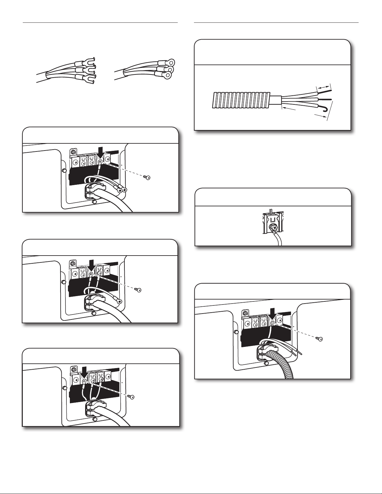
Power Supply Cord Connection
Use where local codes permit connecting cabinet-ground
conductor to neutral wire.
A B
Direct Wire Connection
3. Prepare your 3-wire cable for
direct connection
25 mm
(1")
A. Spade terminal with up-turned ends
B. 19 mm (3/4") strain relief with ring terminals
3. Connect neutral wire
Connect neutral wire of power supply cord to the right terminal
screw of the terminal block. Securely tighten screw.
4. Connect ground wire
89 mm
(3½")
Direct wire cable must have 1.52 m (5 ft) of extra length so
dryer may be moved if needed.
Strip 89 mm (31/2") of outer covering from end of cable. Strip
insulation back 25 mm (1"). If using 3-wire cable with ground
wire, cut bare wire even with outer covering. Shape wire ends
into hooks.
4. Connect wires to terminal block
To connect wires to terminal block, place hooked end of wire
under terminal block screw, facing to the right. Squeeze
hooked end together and securely tighten screw.
Connect ground wire to the center terminal.
screw.
Securely tighten
5. Connect active wire
Connect active wire to the left terminal.
and strain relief screws.
Finally, reinsert tab of terminal block cover into slot of dryer
rear panel. Secure cover with hold-down screw. Now, go to
“Venting Requirements.”
12
Securely tighten screw
5. Connect neutral wire
Place hooked end of neutral wire of power supply cable
under the right screw of terminal block (hook facing right).
Squeeze hooked end together.
Securely tighten screw.
Page 13
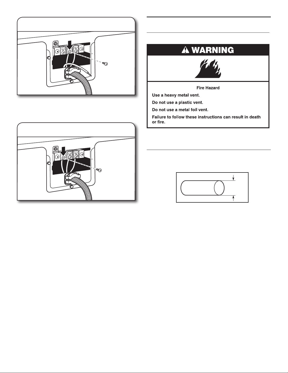
6. Connect ground wire
Place hooked end of ground wire power supply cable
under the center terminal block screw (hook facing right).
Squeeze hooked end together and securely tighten screw.
VENTING
Venting Requirements
7. Connect active wire
Place hooked end of the active wire power supply cable
under the left terminal block screw (hook facing right).
Squeeze hooked end together. Securely tighten screw
and strain relief screw.
Finally, reinsert tab of terminal block cover into slot of dryer
rear panel. Secure cover with hold-down screw. Now, go to
“Venting Requirements.”
WARNING: To reduce the risk of re, this dryer MUST BE
EXHAUSTED OUTDOORS.
IMPORTANT: Observe all governing codes and ordinances.
Dryer exhaust must not be connected into any gas vent,
chimney, wall, ceiling, attic, crawlspace, or a concealed space
of a building. Only rigid or exible metal vent shall be used for
exhausting.
102 mm
4"
(4")
(102 mm)
102 mm (4") heavy metal exhaust vent
n Only a 102 mm (4") heavy metal exhaust vent and clamps
may be used.
n Do not use plastic or metal foil vent.
Rigid metal vent:
n Recommended for best drying performance and to avoid
crushing and kinking.
Flexible metal vent: (Acceptable only if accessible to clean)
n Must be fully extended and supported in nal dryer location.
n Remove excess to avoid sagging and kinking that may result
in reduced airow and poor performance.
n Do not install in enclosed walls, ceilings, or oors.
n The total length should not exceed 2.4 m (7
NOTE: If using an existing vent system, clean lint from entire
length of the system and make sure exhaust hood is not plugged
with lint. Replace plastic or metal foil vents with rigid metal
or exible metal vents. Review “Vent System Chart” and, if
necessary, modify existing vent system to achieve best drying
performance.
3
/4 ft.).
13
Page 14
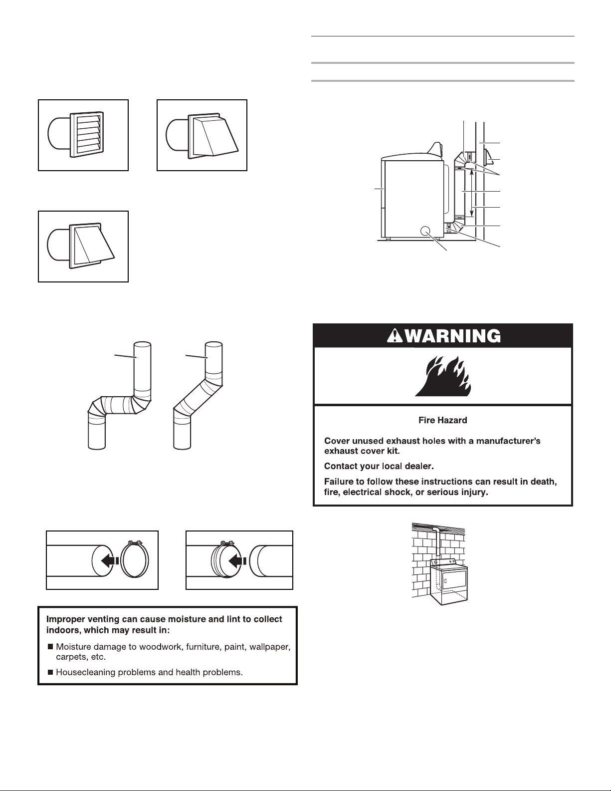
Exhaust hoods:
B
I
A
n Must be at least 305 mm (12") from ground or any object
that may obstruct exhaust (such as owers, rocks, bushes,
or snow).
Recommended Styles:
Louvered hood Box hood
Acceptable Style:
Plan Vent System
Recommended exhaust installations
Typical installations vent the dryer from the rear of the dryer.
Other installations are possible.
C
D
E
F
G
B
H
Angled hood
Elbows:
n 45° elbows provide better airow than 90° elbows.
Good
Better
Clamps:
n Use clamps to seal all joints.
n Exhaust vent must not be connected or secured with screws
or other fastening devices that extend into interior of duct
and catch lint. Do not use duct tape.
A. Dryer
B. Elbow
C. Wall
D. Exhaust hood
E. Clamps
F. Rigid metal or exible metal vent
G. Vent length necessary to connect elbows
H. Exhaust outlet
I. Optional side exhaust outlet
Standard rear offset exhaust installation
See “Venting Kits” for more information.
14
Page 15
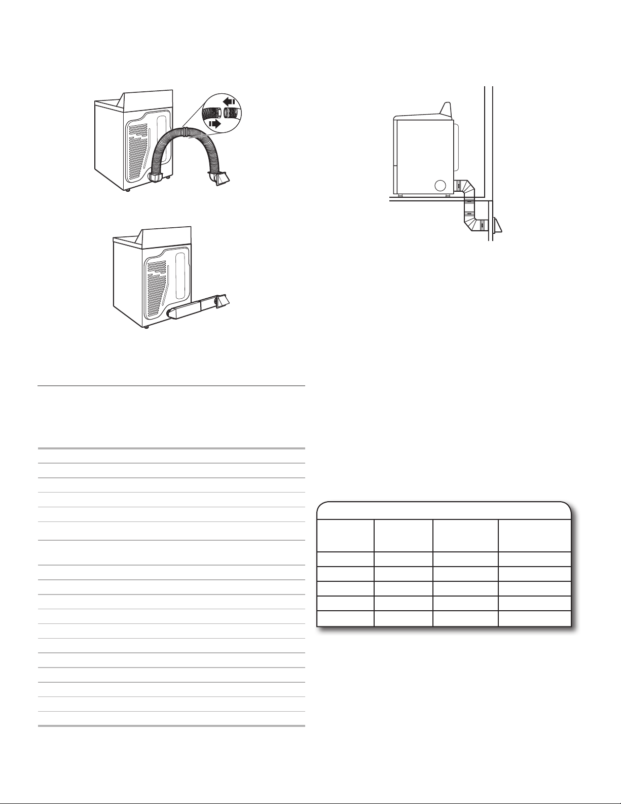
Alternate installations for close clearances
Venting systems come in many varieties. Select the type best
for your installation. Two close-clearance installations are shown.
Refer to the manufacturer’s instructions.
Over-The-Top installation (also available with one offset elbow)
Periscope installation
NOTE: The following kits for close clearance alternate
installations are available for purchase.
Venting Kits
For more information, visit us at www.whirlpool.com/accessories
or contact the dealer from whom you purchased your dryer or an
authorised service company.
Part Number Descriptions
8171587RP 0–5" Metal vent periscope
4396037RP 0"–18" Metal vent periscope
4396011RP 18"–29" Metal vent periscope
4396014 29"–50" Metal vent periscope
4392892 In-Wall metal DuraVent™ Periscope
4396028 Sure Connect™ venting kit
(over-the-top installation)
4396009RP 5' Universal connect vent, exible dryer venting
4396010RP 6' SecureConnect™ vent, exible dryer venting
4396013RB Dryer vent installer’s kit
4396033RP 5' exible dryer venting with clamps
4396727RP 8' exible dryer venting with clamps
4396004 Dryer offset elbow
4396005 Wall offset elbow
4396006RW DuraSafe™ close elbow
4396007RW Through-the-wall vent cap
4396008RP 4" steel dryer venting clamps—2 pack
8212662 Flush-mounting louvered vent hood 4"
Special provisions for mobile home installations:
The exhaust vent must be securely fastened to a noncombustible
portion of the mobile home structure and must not terminate
beneath the mobile home. Terminate the exhaust vent outside.
Determine vent path:
n Select route that will provide straightest and most direct path
outdoors.
n Plan installation to use fewest number of elbows and turns.
n When using elbows or making turns, allow as much room
as possible.
n Bend vent gradually to avoid kinking.
n Use as few 90° turns as possible.
Determine vent length and elbows needed for best
drying performance:
n Use following “Vent System Chart” to determine type of vent
material and hood combinations acceptable to use.
NOTE: Do not use vent runs longer than those specied
in “Vent System Chart.” Exhaust systems longer than those
specied will:
n Shorten life of dryer.
n Reduce performance, resulting in longer drying times and
increased energy usage.
The “Vent System Chart” provides venting requirements that
will help achieve best drying performance.
Vent System Chart
Number of
90° turns
or elbows
0 Rigid metal 20 m (64 ft.) 17.7 m (58 ft.)
1 Rigid metal 16.5 m (54 ft.) 14.6 m (48 ft.)
2 Rigid metal 13.4 m (44 ft.) 11.6 m (38 ft.)
3 Rigid metal 10.7 m (35 ft.) 8.8 m (29 ft.)
4 Rigid metal 8.2 m (27 ft.) 6.4 m (21 ft.)
Type
of vent
Box/
louvered
hoods
Angled
hoods
15
Page 16
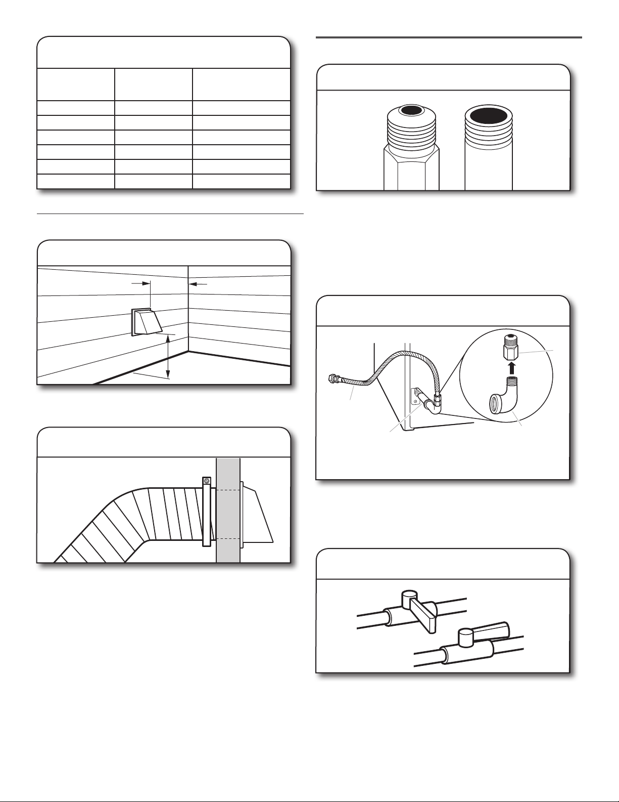
12" min.
(305 mm)
12" min.
(305 mm)
A
B
C
D
A
B
Vent System Chart
(Long Vent Models Only)
Number of
90° turns
or elbows
0 Rigid metal 36.6 m (120 ft.)
1 Rigid metal 33.5 m (110 ft.)
2 Rigid metal 30.5 m (100 ft.)
3 Rigid metal 27.4 m (90 ft)
4 Rigid metal 24.4 m (80 ft)
5 Rigid metal 21.3 m (70 ft.)
Type
of vent
or Angled hoods
Install Vent System
1. Install exhaust hood
305 mm min.
Box/louvered
(12" min.)
MAKE GAS CONNECTION
1. Connect gas supply to dryer
Flared
male tting
Remove red cap from gas pipe. Using a wrench to tighten,
connect gas supply to dryer. Use pipe-joint compound
on threads of all non-ared male ttings. If exible metal
tubing is used, be sure there are no kinks.
NOTE: For propane gas connections, you must use pipe-joint
compound resistant to action of propane gas. Do not use
TEFLON® tape.
Non-ared
male tting
2. Plan pipe tting connection
305 mm min.
(12" min.)
Install exhaust hood and use caulking compound to seal
exterior wall opening around exhaust hood.
2. Connect vent to exhaust hood
Vent must t over the exhaust hood. Secure vent to exhaust
hood with 102 mm (4") clamp. Run vent to dryer location
using straightest path possible. Avoid 90° turns. Use clamps
to seal all joints. Do not use duct tape, screws, or other
fastening devices that extend into interior of vent to secure
vent, because they can catch lint.
A. 9.5 mm (3/8") exible gas
connector
B. 9.5 mm (3/8") dryer pipe
A combination of pipe ttings must be used to connect dryer
to existing gas line. A recommended connection is shown.
Your connection may be different, according to supply line
type, size, and location.
C. 9.5 mm (3/8") to 9.5 mm (3/8")
pipe elbow
D. 9.5 mm (3/8") pipe-to-are
adapter tting
3. Open shut-off valve
Closed valve
A
Open valve
B
16
Open shut-off valve in supply line; valve is open when handle
is parallel to gas pipe. Then, test all connections by brushing
on an approved noncorrosive leak-detection solution.
Bubbles will show a leak. Correct any leaks found.
Page 17
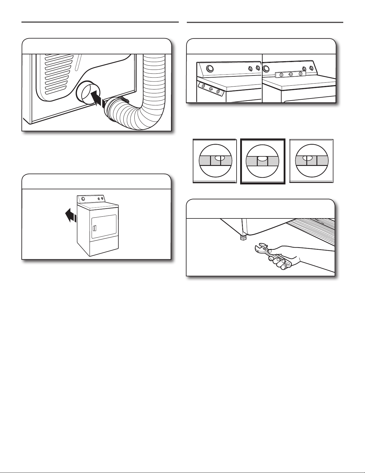
CONNECT VENT
LEVEL DRYER
1. Connect vent to exhaust outlet
Using a 102 mm (4") clamp, connect vent to exhaust outlet
in dryer. If connecting to existing vent, make sure vent is
clean. Dryer vent must t over dryer exhaust outlet and inside
exhaust hood. Check that vent is secured to exhaust hood
with a 102 mm (4") clamp.
2. Move dryer to nal location
1. Level dryer
Check levelness of dryer from side to side. Repeat from
front to back.
NOTE: The dryer must be level for the moisture sensing system
to operate correctly.
Not Level LEVEL Not Level
2. Tighten and adjust leveling legs
Move dryer to nal location. Avoid crushing or kinking vent.
After dryer is in place, remove corner posts and cardboard
from under the dryer.
If dryer is not level or the same height as the washer, prop up
using a wood block. Use wrench to adjust legs up or down
and check again for levelness. Once legs are level, make sure
all four legs are snug against the oor before tightening them.
17
Page 18
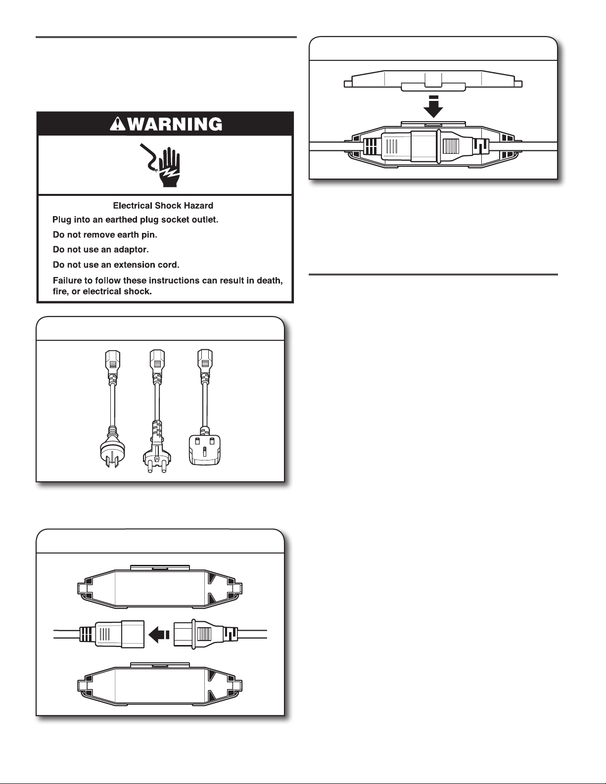
POWER CORD INSTALLATION
(on some models)
IMPORTANT: To be performed by Whilrpool Corporation
authorised service personnel only.
1. Select plug
Select the plug that fits with the electric receptacle.
NOTE: Plug types and quantities will vary by model.
2. Assemble plug
3. Secure power cord
Secure the power cord by seating the connection on the cord
lock. Place the cord lock cover and push until it snaps. Make
sure the power cord connection is seated on the cord lock
and that the cord lock clamps correctly.
Plug power supply cord into an earthed outlet. Turn power
supply on.
COMPLETE INSTALLATION
CHECKLIST
Check that all parts are now installed. If there is an extra
q
part, go back through steps to see what was skipped.
Check that you have all of your tools.
q
Dispose of/recycle all packaging materials.
q
Check dryer’s nal location. Be sure vent is not crushed
q
or kinked.
Check that dryer is level. See “Level Dryer.”
q
Remove lm on console and any tape remaining on dryer.
q
Wipe dryer drum interior thoroughly with a damp cloth
q
to remove any dust.
Read “Dryer Use” in your Use and Care Guide.
q
Set the dryer on a full heat cycle (not an air cycle) for
q
20 minutes and start the dryer.
If the dryer will not start, check the following:
n Dryer is plugged into an earthed 3-prong outlet.
n Electrical supply is connected.
n Household fuse is intact and tight or circuit breaker has
not tripped.
n Dryer door is closed.
When the dryer has been running for 5 minutes, open the
q
dryer door and feel for heat. If you feel heat, cancel cycle
and close the door.
If you do not feel heat, turn the dryer off and check to see
whether gas supply line shut-off valve is open.
n If the gas supply line shut-off valve is closed, open it,
then repeat the 5-minute test as outlined above.
n If the gas supply line shut-off valve is open, contact
a qualied technician.
NOTE: You may notice an odor when the dryer is rst heated.
This odor is common when the heating element is rst used.
The odor will go away.
Assemble the plug into the end of the power cord located on
the back of the dryer.
18
Page 19
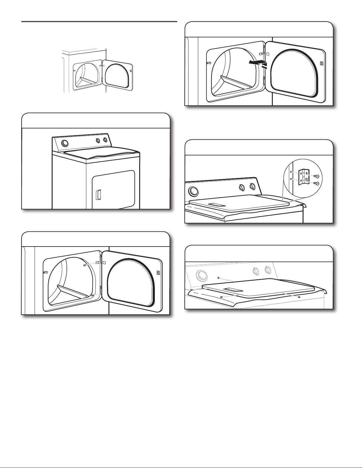
REVERSE DOOR SWING
(OPTIONAL)
NOTE: Magnetized screwdriver is helpful.
1. Place towel on dryer
3. Lift door off top screws
Lift door until top screws in dryer cabinet are in large part of
hinge slot. Pull door forward off screws. Set door (handle side
up) on top of dryer. Remove top screws from dryer cabinet.
4. Remove screws from hinges
Place towel on top of dryer to avoid damaging the surface.
2. Remove bottom screws
Open dryer door. Remove bottom screws from dryer cabinet
side of hinges. Loosen (do not remove) top screws from dryer
cabinet side of hinges.
Remove screws attaching hinges to door.
5. Remove screws from door
Remove screws at top, bottom, and side of door (4 screws)
that hold the inner and outer door together. Holding door over
towel on dryer, grasp sides of outer door and lift to separate
it from inner door. Set outer door aside.
NOTE: Do not pry apart with putty knife or screwdriver.
Do not pull on door seal or plastic door catches.
19
Page 20
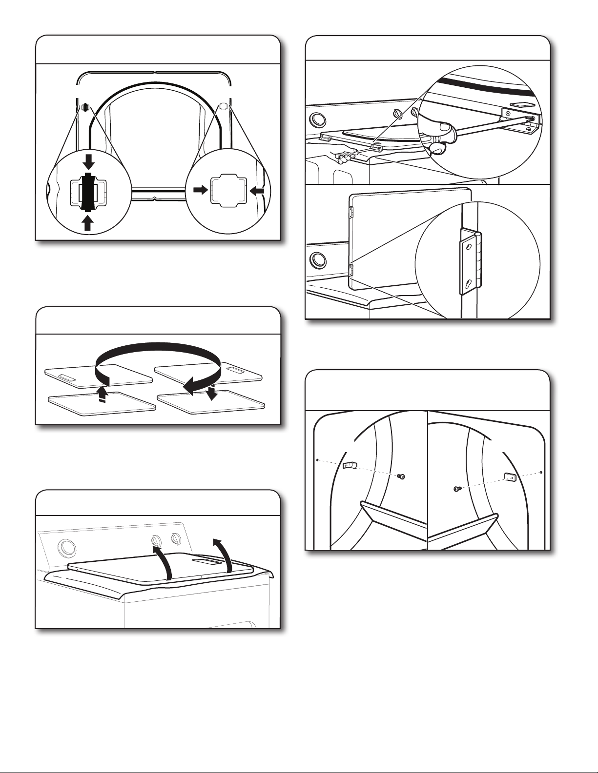
6. Switch door catch, bezel, and plug
9. Attach door hinges
Catch and bezel
Remove the door catch, bezel, and plug from the inside of
the inner door by squeezing and pulling/pushing them. Place
the door catch, bezel, and plug on the sides opposite from
where they were.
Plug
7. Rotate outer door
Reattach door hinges to dryer door so that the larger hole is
at the bottom of the hinge.
Rotate outer door 180º and set it back down on inner door.
Reattach outer door panel to inner door panel so handle is
on the side where hinges were just removed. Insert 4 door
screws.
8. Flip door over
Flip door over so handle side is down.
10. Remove door strike and
door strike plug
Door strike plugDoor strike
Remove door strike and door strike plug from dryer cabinet.
Insert the door strike into door strike plug hole and secure
with screw. Insert door strike plug into original door strike
hole and secure with screw.
20
Page 21
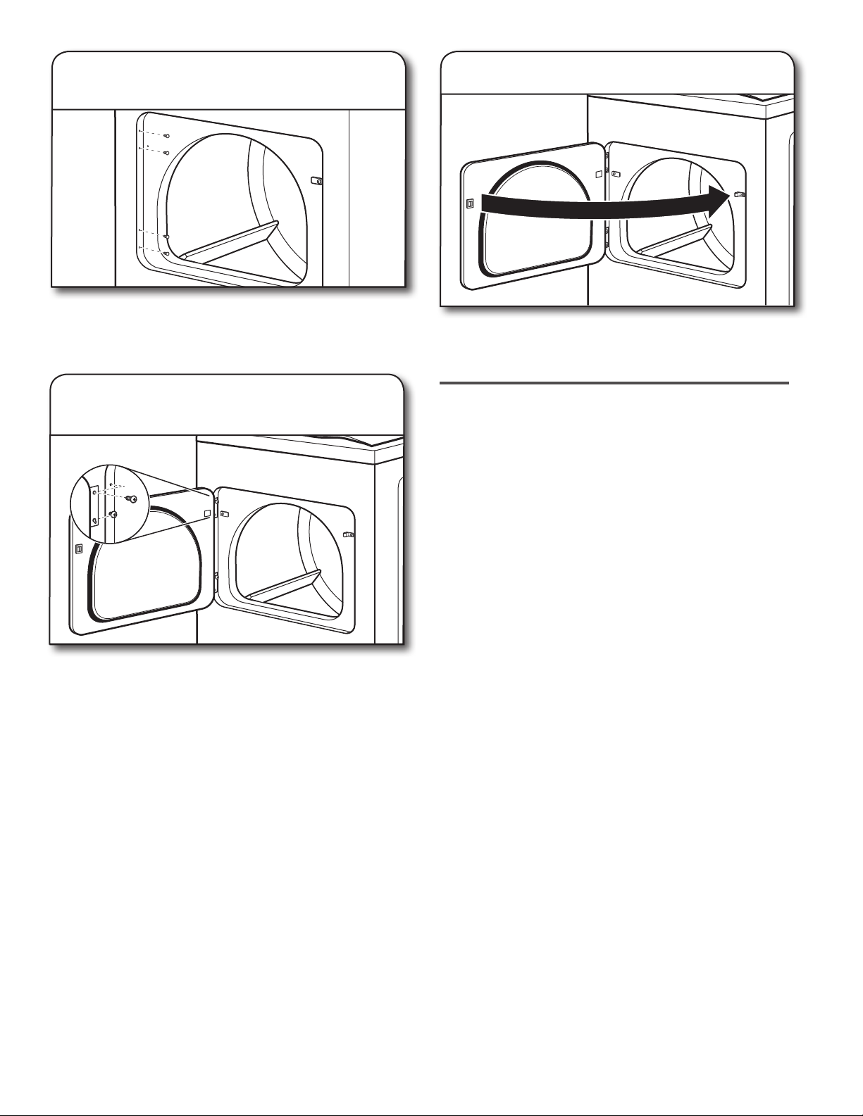
11. Remove and transfer
hinge hole plugs
Use a small, at-blade screwdriver to gently remove 4 hinge
hole plugs on left side of dryer cabinet. Transfer plugs into
hinge holes on opposite side of dryer cabinet.
13. Check door strike alignment
Close door and check that door strike aligns with door
catch. If it is needed, slide door catch left or right within
slot to adjust alignment.
12. Insert screws in hinge holes
on dryer cabinet
NOTE: Two people may be needed to reinstall door.
Insert screws into the bottom holes on left side of dryer
cabinet. Tighten screws halfway. Position door so large
end of door hinge slot is over screws. Slide door up so
screws are in bottom of slots. Tighten screws. Insert
and tighten top screws in hinges.
TROUBLESHOOTING
See the Use and Care Guide or visit our website and
reference “Frequently Asked Questions” to possibly
avoid the cost of a service call.
21
Page 22

Whirlpool Corporation, 2000 N M 63, Benton Harbor, MI 49022 US
www.whirlpool.com/accessories
02/17
Whirlpool2017
W10849532D
 Loading...