

Page 1

InstalloHon Instructions
Page 2
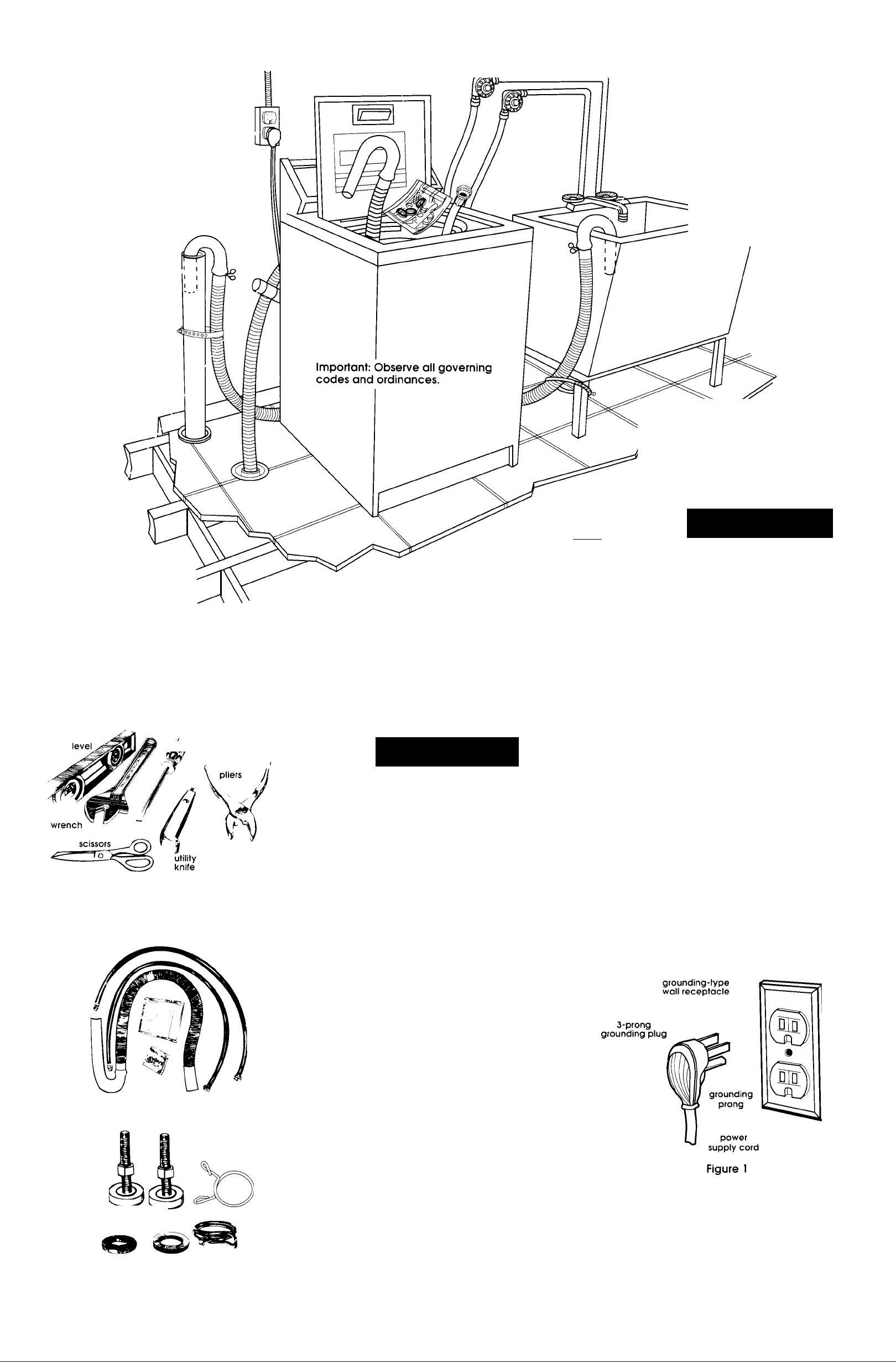
Before yott start...
Check location where washer will be
installed, Proper installation is your
responsibility. Make sure you have
everything necessary for correct
installation,
Grounded electrical outlet is
required. See Electrical
requirennents.
Standpipe drain system: Needs a
two-inch (51 mm) minimum
diameter standpipe with minimum
carry-away capacity of
17 gallons (64 liters)
per minute.
Top of standpipe
must be at least
34 inches (86 cm)
high and no
higher than
72 inches (132 cm)
from bottom of
washer.
Untape and open washer lid.
Remove packages, hoses and
literature pack from washer.
Hot and cold water faucets: Must be
within 4 feet (122 cm) of the back of the
washer and provide water pressure 5-100
PSI (34.5-689,6 KPa),
Laundry tub drain system: Needs a 20gallon (76 liter) laundry tub. Top of tub
must be at least 34 inches (86 cm) high
and no higher than 52 inches (132 cm)
from bottom of washer.
Maximum height must not
exceed 52 inches (132 cm)
with 50 Hz power and 72
inches (183 cm) with 60 Hz
power from bottom of
washer.
Water heater: Set
to deliver 140°F
(60°C) water to
washer.
Maximum height must
not exceed 52 inches
(132 cm) with 50 Hz
power and 72
inches (183 cm)
with 60 Hz power
from bottom
of washer.
Floor drain
system
requires a
siphon break,
Part No,
285320,
Tools needed for
Support: Floor must be sturdy
enough to support washer
weight of 315 pounds (143kg).
Electrical
Level floor:-Maximum
slope under entire
washer— 1 inch (25 cm).
Hecommended
If a longer drain hose is needed, drain
hose (Part No. 388423) and hose
extension kit (Part No. 285442) are
avaiiabie from Whiripooi-authorized
parts distributors. If drain hose must be
shortened, use kit (Part No. 285442).
A CAUTION
Product Damage
Do Not store or operate washer
below 32°F (0°C) (some water
may remain in washer).
See Use & Care Guide for
“Winterizing” information.
Failure to follow above may
result in product damage.
installation:
flat-blade
MM/ screwdriver
Parts supplied for installation:
requirements
Awarning
Electrical Shock Hazard
• Electrical ground is required on
this appliance.
• If cold water pipe is interrupted by
plastic, non-metallic gaskets or other
insulating materials, Do Not use for
grounding.
• Do Not ground to a gas pipe.
• Do Not modify the power supply cord
plug. If it does not fit the outlet, have a
proper outlet installed by a qualified
electrician.
• Do Not have a fuse in the neutral or
grounding circuit. A fuse in the neutral
or grounding circuit could result in an
electrical shock.
• Do Not use an extension cord with this
appliance.
•Check with a qualified electrician if
you are in doubt as to whether the
appliance is properly grounded.
Failure to follow these instructions could
result in serious injury or death.
grounding method
For your personai safety, this appliance
must be grounded. This appliance is
equipped with a power suppiy cord
having a 3-prong grounding plug. To
minimize possible shock hazard, the cord
must be plugged into a mating
3-prong grounding-type wall receptacle,
grounded in accordance with National
Electrical Codes, and all local codes and
ordinances. See Figure 1, If a mating wall
receptacle is not available, it is the
personal responsibility and obligation of
the customer to have a properly
grounded 3-prong wall receptacle
installed by a qualified electrician.
3-prong
Remove parts from packages. Check
that ail parts were included.
literature package
1 drain hose
1 hose clamp
2 inlet hoses
4 flat water hose washers
2 front leveling legs
with nuts
1 small clamp
Panel A
If codes permit and a separate grounding
wire is used, it is recommended that a
qualified electrician determine that the
grounding path is adequate.
A 120-volt, 50/60-Hz, AC-only, 15- or 20ampere fused electrical supply is required.
(Time-delay fuse or circuit breaker is
recommended.) It is recommended that
a separate circuit serving only this
appliance be provided.
Page 3
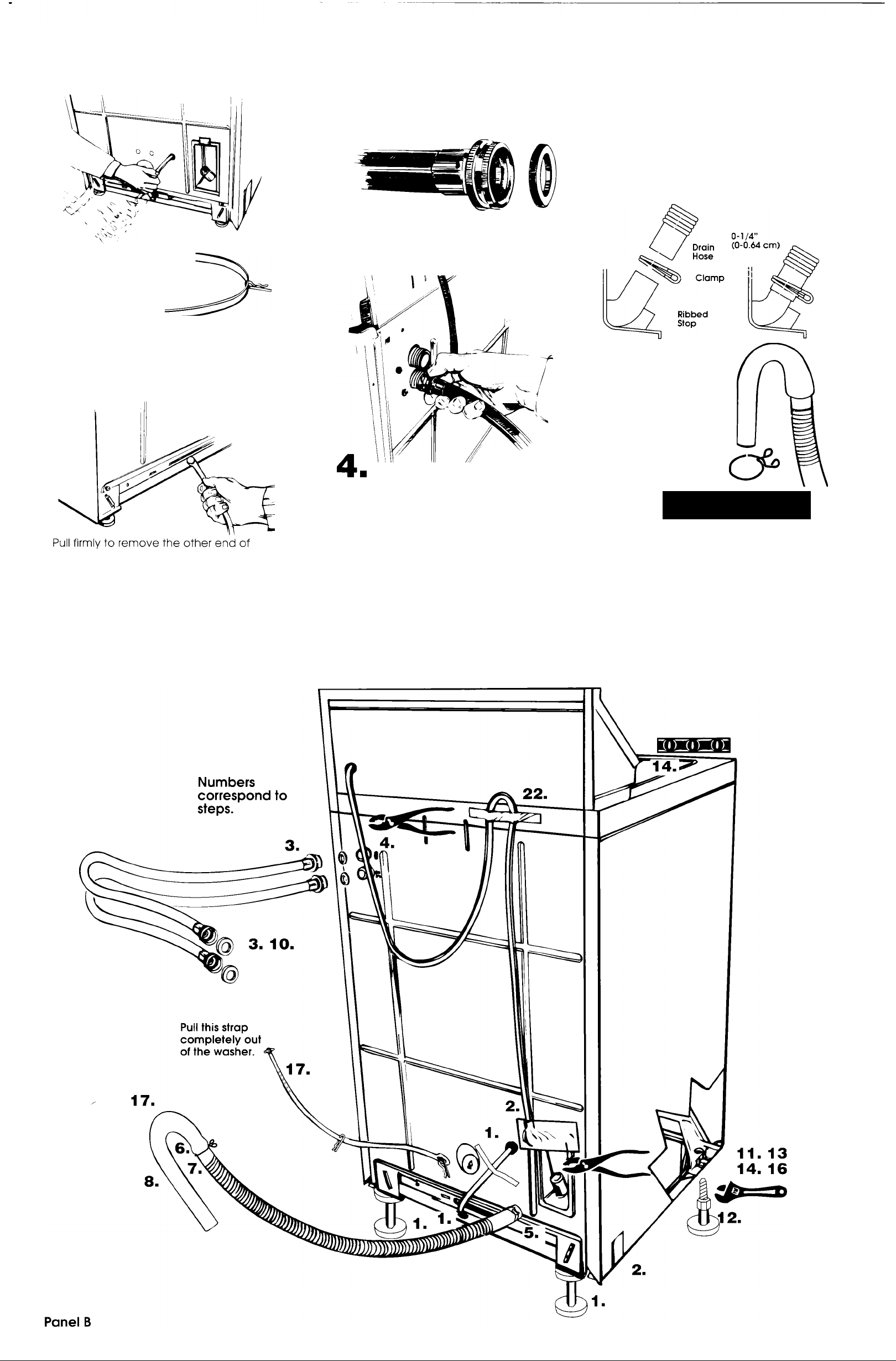
Now start...
With washer in laundry area.
Pull the strap
completely out of
the washer.
I ■ Pull to completely remove the
shipping strop with 2 cotter pins from the
Inside of the washer,
shipping strap from the back of the
washer. The shipping strap plug must be
completely removed from the washer for
the self-leveling legs fo be released,
Save the shipping strap for use in Step 17.
^mrn Read, then remove label that
covers power cord and drain connector,
Peel the tape down and off each side of
cabinet.
Use new hoses and washers that came
with your washer.
coupling washer
■ Insert a flat washer into each end
3
of the inlet hoses. Check that washers are
firmly seated in couplings.
Inlets are plastic.
Do not strip or
crossthread.
Attach hose to bottom inlet valve
opening first; then second hose to top
inlet. Tighten couplings by hand. Then
use pliers to make an additional twothirds turn.
IMPORTANT: THIS PROCEDURE MUST BE
FOLLOWED TO ASSURE PROPER
INSTALLATION.
To prevent the drain hose from
■ coming off or leaking, it must be
5
installed per the following instructions:
1. Wet the inside end of the drain hose
with tap water, DO NOT USE ANY
OTHER LUBRICANT.
2, Squeeze ears of clamp with pliers to
open and place clamp over the
end of the drain hose,
3, While holding clamp open, work
end of drain hose onto drain
connector until drain hose is within
1/4 inch (0,64 cm) of ribbed stop,
4, When the end of the drain hose is
within 1 /4 inch (0,64 cm) of ribbed
stop, position clamp on drain hose
so that the bottom of the clamp is
1/4 inch (0.64 cm) from the end of
the hose, release pliers.
0-1/4”
max.
(0-0.64
cm)
Open
clamp and slide
over "hook" end of
drain hose to
secure the rigid
and corrugated
sections together
A CAUTION
Floor Damage
Slide washer onto cardboard or
hardboard before moving across fioor.
Faiiure to do so may cause damage to
floor covering.
■ ■ Move washer close to final
position. Put "hook" end of drain hose
into laundry tub or standpipe. Check for
proper length of drain hose.
Page 4
8
OF DRAIN HOSE DOWN THE STANDPIPE.
THIS COULD CAUSE SIPHONING.
DO NOT FORCE EXCESS LENGTH
9
hose, run water through both faucets into
a bucket, This will get rid of particles in
the water lines that might clog hoses.
Mark which is the hot water faucet.
10
marked "H" to hot water faucet. Attach
top hose (inlet marked "C") to cold water
faucet, Tighten couplings to faucets by
hand; then use pliers to make final twothirds turn.
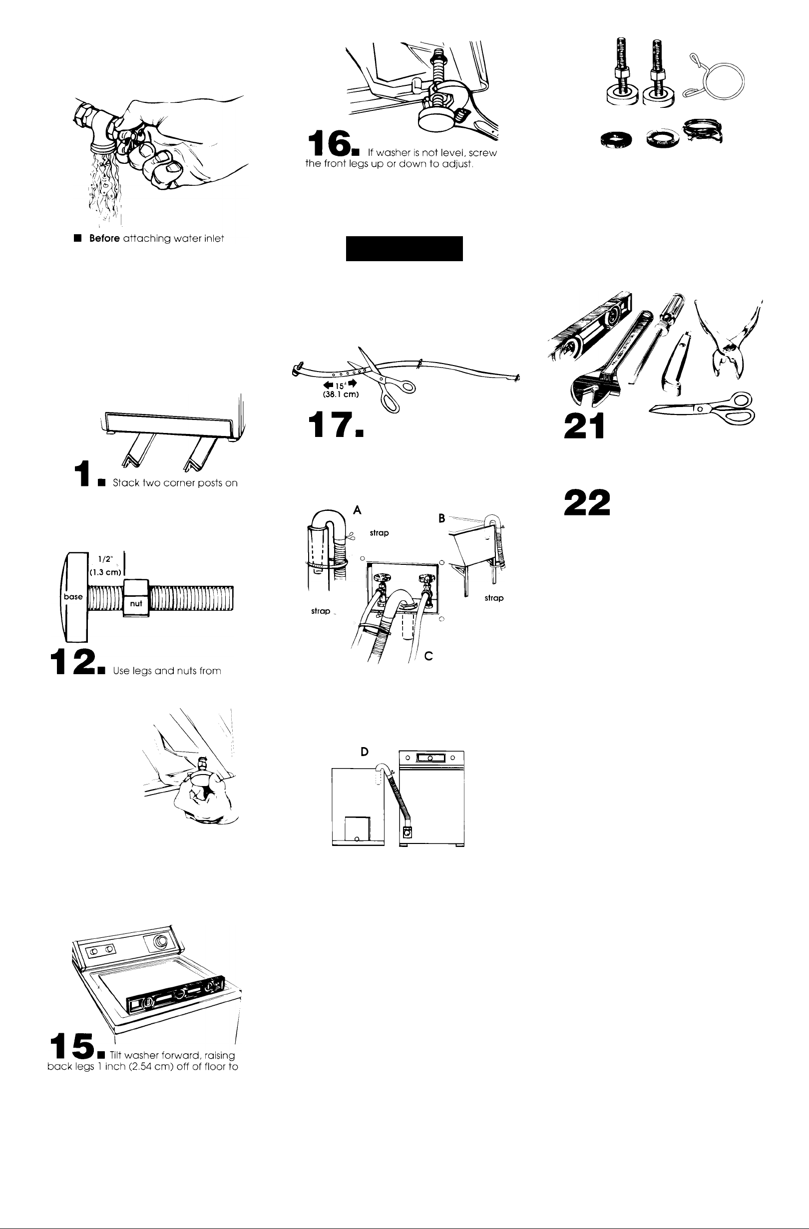
top of each other. Tilt washer backwards
and insert corner posts 3 inches (7,6 cm)
in from one side of washer as shown.
Repeaf with other corner posts on other
side of washer.
Attach bottom hose (inlet
Repeat Step 15.
When washer is level, use wrench to turn
nuts on front legs up tightly against washer
base. If nuts are not tight against washer
base, the washer may vibrate.
A CAUTION
Property Damage
Secure the drain hose to the tub or
standpipe with the shipping strap
removed from the back of the washer.
Failure to properly secure drain hose
could result in water damage.
Measure and mark a point
approximately 15 inches (38.1 cm) from
the plug end of the shipping strap. Cut
the shipping strap at this point.
Check that hose is not twisted or kinked
and is securely in place.
19
installed. See parts list. Panel A, If there is
an extra part, go back through steps to
see which step was skipped.
20
check for leaks. Tighten couplings if there
is leaking. DO NOT OVERTIGHTEN; this
could cause damage to faucet.
your fools. Check that the shipping strap
with 2 cotter pins and plug was removed
from the back of the washer and used to
secure the drain hose.
Check that all parts are now
Turn on water faucets and
■ Check that you have all of
I Untape power supply cord
and plug into grounded outlet.
parts package. Screw nut down to
within 1 /2 inch (1,3 cm) of base.
13.
Insert legs into
correct holes at
each front corner
of washer until
nuts touch
washer. Do Not
tighten nuts until
Step 16,
Put 'hook" end of drain hose in fub or
standpipe. Tightly wrap the shipping strap
around the drain hose and tub or
standpipe or inlet hose as shown in
Figures A-C, Push plug into the nearest
hole in the shipping strap.
23
read the Use and Care Guide to fully
undersfand your new washer. Now start
the washer and allow it to complete the
regular cycle.
from your new washer, read your
Whirlpool Use and Care Guide.
Take a few minufes and
You have
successfully installed
your new Whirlpool washer.
To get the most efficient use
Congratulations!
Keep Installation Instructions and
Guide. The instructions will make
reinstalling your Whirlpool
washer in another home
as easy as the first
installation.
14
remove corner post(s). Gently lower
washer to floor.
Move washer to its final location. Remove
cardboard or hardboard from under
washer.
adjust rear self-leveling legs. Gently lower
washer to floor. Check levelness of the
washer by placing a carpenter's level on
top of fhe washer, first side to side; then
front to back.
Tilt washer backward and
If a longer drain hose is needed, drain
hose (Part No. 388423) and hose
extension kit (Part No. 285442) are
available from authorized parts
distributors. If drain hose must be
shortened, use hose kit (Part No. 285442),
Note: If washer is moved to adjust drain hose, the
washer must be leveled again. Repeat Steps 15-16.
Place cardboard under the washer and carefully
move washer to avoid damaging floor covering.
18 ■ CHECK ELECTRICAL
REQUIREMENTS. BE SURE YOU HAVE
CORRECT ELECTRICAL SUPPLY AND
RECOMMENDED GROUNDING METHOD.
Panel C
Page 5
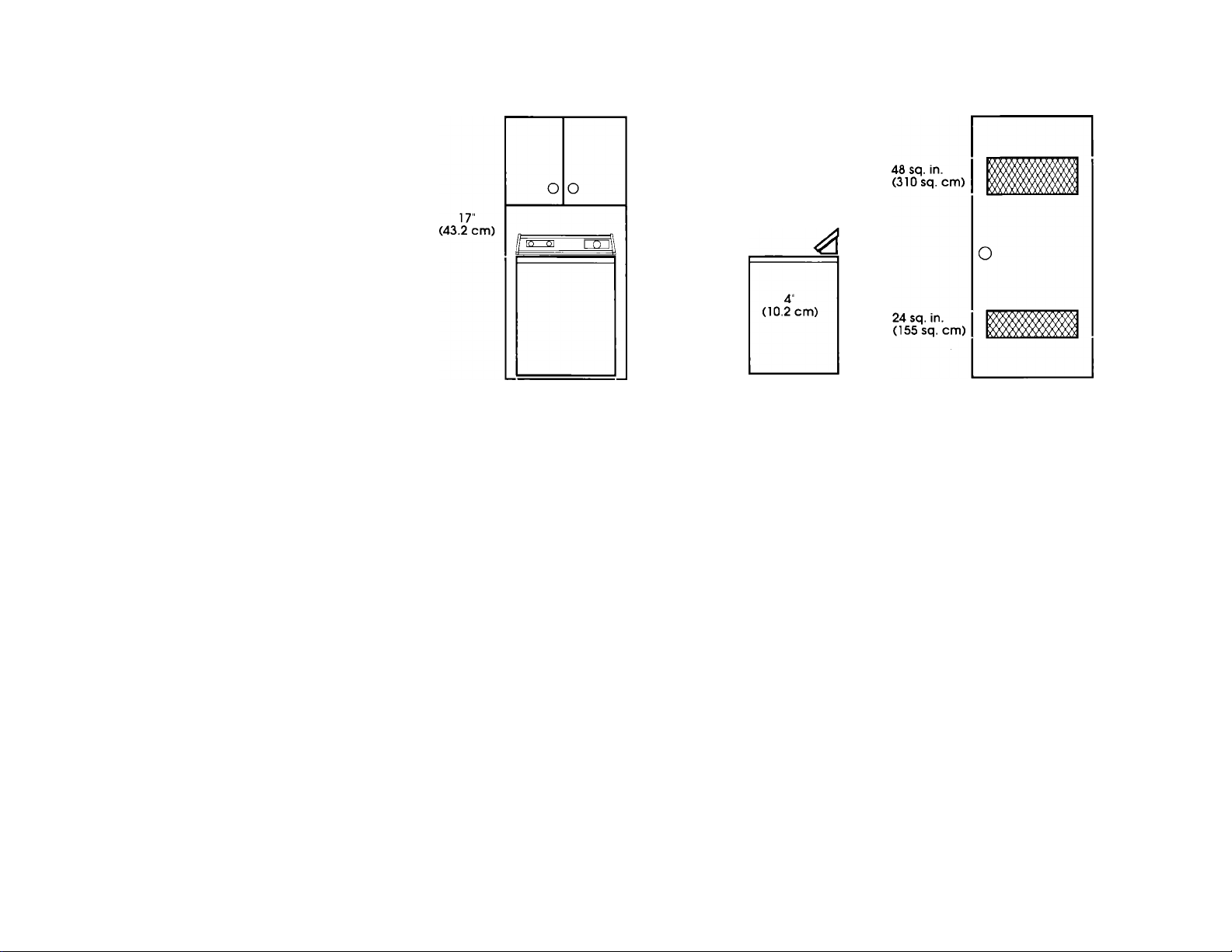
Recessed area instructions...
This washer may be installed in a
recessed area or closet.
The installation spacing is in inches and is
minimum allowable. Additional spacing
should be considered for ease of
installation and servicing.
If closet door is installed, the minimum air
openings in top and bottom are required,
Louvered doors with air openings in top
and bottom are acceptable.
Companion appliance spacing should
be considered.
If you need assistance...
Call your dealer or local authorized
service company.
When you oall, you will need the washer
model number and serial number. Both
numbers are on the serial/rating plate
located under the washer lid and on the
top of fhe washer.
48 sq. in.
(310 sq. cm)
24 sq. in.
(155 sq. cm)
(0 cm) (0 cm)
Additional clearances for wall, door
and floor moldings may be required.
(door not shown)
0" 0"
Front view
Closet door
14" max.
(35.6 cm
max.)
1" min.
(2.5 cm min.)
Side view Front view
Minimum installation spacing
3"
(7.6 cm)
3"
(7.6 cm)
Part No. 3358968
© 1992 Whirlpool Corporation
AiVhirlp<M)l
Prepared by Whirlpool Corporation, Benton Harbor, Michigan 49022
/ JL CORPORATION
Printed in U.S.A,
 Loading...