

Page 1
Quick Reference
Table of Contents:
Pages
Product dimensions
Cabinet opening dimensions
Before you start
Electrical requirements
Installation steps
If you need assistance:
Check your Use and Care Guide for a toll-free number to call or call
the dealer from whom you purchased this appliance. The dealer is
listed in the Yellow Pages of your phone directory under
“Appliances — Household — Major — Service and Repair.”
Call when you:
嘼 Have questions about range installation or operation.
嘼 Need to obtain the name and number of an authorized service
company.
When you call, you will need:
嘼 The range model number:
嘼 The range serial number:
Both numbers are listed on the model/serial rating plate, located on
the oven door or on the oven frame.
1
1
1
2
23
IMPORTANT:
Read and save these instructions.
Installation Instructions
IMPORTANT:
Installer: Leave Installation Instructions with the homeowner.
Homeowner: Keep Installation Instructions for future reference.
Save Installation Instructions for local electrical inspector's use.
Part No.
3191799 Rev. A
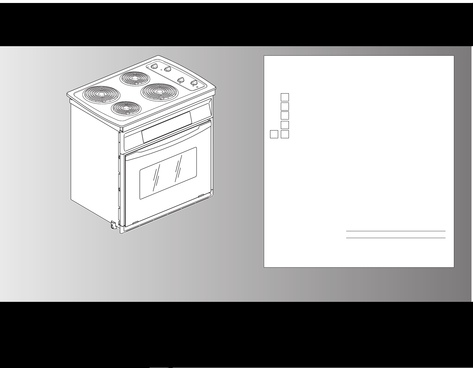
30" Drop-In
Electric Range
Page 2

This is the safety alert symbol.
This symbol alerts you to hazards that can kill or
hurt you and others. All safety messages will be
preceded by the safety alert symbol and the word “DANGER”
or “WARNING”. These words mean:
Page 1
2 screws
2 door removal pins
Phillips
screwdriver
1/2" dia.
router bit
Product dimensions
Before you start...
30-3/4"
recessed
height
from
underside
of cooktop
to support
slats
28-3/16"
cooktop
recessed width
23-1/8"
recessed
depth
shipping
foot
31-11/16"
overall
height
Important: Observe all governing codes and
ordinances.
Proper installation is your responsibility. Have a qualified
technician install this range.
Range location should be away from strong draft areas,
such as windows, doors and strong heating vents.
Cabinet opening dimensions that are shown must be used.
Given dimensions provide minimum clearance.
Recessed installation area must provide complete
enclosure around the recessed portion of the range.
Electrical ground is required. See “Electrical requirements.”
IMPORTANT: Some cabinet and building materials are not
designed to withstand the heat produced by the oven for
baking and self-cleaning. Check with your builder or cabinet
supplier to make sure that the materials used will not
discolor, delaminate or sustain other damage.
Range support surface MUST be solid, level and flush with
bottom of cabinet cutout.
Do not seal range to side cabinets.
When installing a cooktop under existing cabinets and the
installation does not meet the minimum cabinet clearances.
Install a range hood above the cooktop to avoid burn
hazards.
Copies of the standards listed may be obtained from:
**
National Fire Protection Association
Batterymarch Park
Quincy, Massachusetts 02269
Tools needed:
Parts supplied:
It is the customer’s responsibility:
To contact a qualified electrical installer.
To assure that the electrical installation is adequate and in
conformance with National Electrical Code, ANSI/NFPA
70 — latest edition**, and all local codes and ordinances.
7/8" min.
required
between
cutout and
cabinet door
or hinge.
Locate electrical
supply junction
box on cutout
floor or on rear
wall (shown)
near floor line.
Top of countertop
Note: countertop
must be level
across front and
front to back.
Front view of
cabinet cutout
For minimum
clearances to the
top of cooktop see
Note.*
*Note: 24" min. when bottom of wood or
metal cabinet is protected by not less than
1/4" flame retardant millboard covered
with not less than No. 28 MSG sheet steel,
0.015" stainless steel, 0.024" aluminum or
0.020" copper.
30" min. clearance between the top of the
cooking platform and the bottom of an
unprotected wood or metal cabinet.
wall
1-1/8"
max.
13" max. upper
cabinet depth
19-5/8"
25" countertop
depth
24" lower
cabinet depth
floor
cabinet
front
Side view of
cabinet cutout
30"
overall
width
You can be killed or
seriously injured if you
don’t follow instructions.
DANGER
WARNING
Your safety and the safety of others is very
important.
We have provided many important safety messages in this
manual and on your appliance. Always read and obey all
safety messages.
All safety messages will identify the hazard, tell you how to
reduce the chance of injury, and tell you what can happen if
the instructions are not followed.
You will be killed or
seriously injured if you
don’t follow instructions.
Mobile home installation
The installation of this range must conform to the
Manufactured Home Construction and Safety Standards,
Title 24 CFR, Part 3280 (formerly the Federal Standard for
Mobile Home Construction and Safety, Title 24, HUD, Part
280); or when such standard is not applicable, the Standard
for Manufactured Homes Installations (Manufactured Home
Sites, Communities and Setups), ANSI A225.1/NFPA 501A,
or with local codes.**
When this range is installed in mobile home, it must be
secured to the floor during transit. Any method of securing
the range is adequate as long as it conforms to the
standards listed above.
Four-wire power supply cable must be used in a mobile
home installation. The appliance wiring will need to be
revised. See four-wire electrical connection, Page 3.
1-1/2" max.
countertop
thickness
Top view of
cabinet cutout
28-5/32" oven
recessed width
31-1/2"
overall
cooktop
width
Cabinet opening dimensions
Install a 3-1/2"-wide
support slat on each
side. Slats must be level
front to back and with
each other.
30-3/4"
top of
counter-
top to
bottom
of cabinet
cutout
30-3/4"
top of
countertop to
support slats
21"
cooktop
depth
24-13/32"
to back
of oven
28-1/2" min.
opening width
28-5/8"
opening is
recommended,
if available.
36" overall
countertop
height
1/4"
radius both
corners
Countertop preparation:
Front edges: You may need to
shave or cut the trim of formed
or metal front-edged
countertops to clear the 30"
width of cooktop.
If countertop thickness is
more than 1-1/2" inches
thick: Countertop must be
notched as shown to avoid
damaging the oven control
panel.
If countertop extends more
1-1/8" beyond cabinet front:
Notch countertop as shown
to clear oven control panel.
30-1/8"
notch width
to be equal
both sides
notch width
to be equal
both sides
1-1/2"
max
30-1/8"
1-1/8"
max
cabinet
front
30”
Page 3
Page 2
Electrical requirements
Installation steps
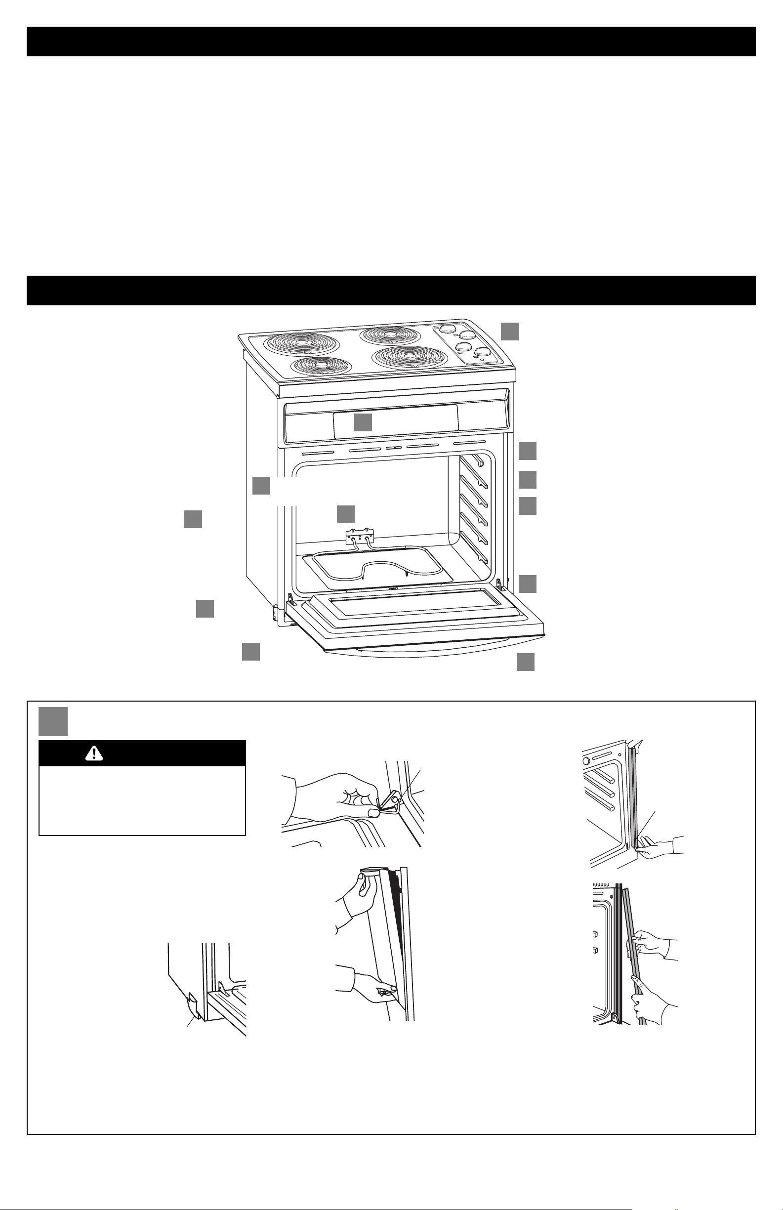
1. Turn power supply
off. Move range close to
final position.
• Remove and discard
shipping materials, tape
and protective film from
the range. Do Not
remove shipping base
or shipping feet at the
front lower corners of
range. The shipping feet will protect the
lower range trim until range is inserted into
cabinet.
• Remove and set aside oven racks and other
parts from inside oven.
Preparation
A
A
Remove trim
screws.
A
Remove
oven door.
C
Reattach side
trim pieces.
A
Remove
side trim.
C
Remove
shipping
feet.
A
Remove
oven racks.
C
Use screws to attach
range to cabinet.
D
Check cooktop
operation.
C
Grasp oven
frame to
lift range.
D
Check oven
operation.
C
Replace
oven door.
B
2.Completely open oven door. Insert small
end of a door removal pin into each door hinge.
Grasp door handle from the bottom and gently
close door as far as it will shut. Lift slightly and
grasp bottom of door with other hand. Pull door
out at bottom to remove. Set door aside on
protected surface.
Insert small
end of pin
here.
Do Not
remove
shipping feet.
3.Remove trim screws attaching right and
left side trim to range. Grasp the bottom end of
trim and pull away from range. Slide top end of
trim downward to remove trim from range. Take
care not to scratch other surfaces with ends of
trim. Set trim and screws aside on protected
surface.
Remove trim screw.
Pull trim out.
Pull top of trim
down.
If codes permit and a separate ground wire is used,
it is recommended that a qualified electrician
determine that the ground path and wire gauge are
in accordance with local codes.
Do Not ground to a gas pipe.
Check with a qualified electrician if you are not sure
range is properly grounded.
Do Not have a fuse in the neutral or ground circuit.
嘼 Flexible armored cable from appliance should
be connected directly to junction box.
嘼 Fuse both sides of the line.
嘼 A U.L.-listed conduit connector must be
provided at the junction box.
嘼 Do Not cut the conduit.
Wire sizes and connections must conform with the
rating of the appliance and to the requirements of
the National Electrical Code, ANSI/NFPA 70 — latest
edition (** See Page 1) and all local codes and
ordinances.
Important: Use both hands to remove oven door.
Do Not use handle or any portion of the front
frame or trim for lifting.
Before moving range across floor, check that
range is on shipping base or slide range onto
cardboard or hardboard.
Do Not remove shipping feet at the front lower
corners of range.
Excessive Weight Hazard
Use two or more people to move and
install range.
Failure to do so can result in back or
other injury.
WARNING
Connect
power
supply
cable.
Range must be connected to the proper electrical
voltage and frequency as specified on the
model/serial rating plate. (The model/serial rating
plate is located on the oven door or on the oven
frame.)
嘼 CONNECT WITH COPPER WIRE ONLY.
嘼 Models rated from 11.8 kW to 13.3 kW at 240
volts (8.9 kW to 10.0 kW at 208 volts) require a
separate 40-ampere circuit.
嘼 A time-delay fuse or circuit breaker is
recommended.
嘼 Connect directly to the fused disconnect (or
circuit breaker box) through flexible, armored
or non-metallic sheathed, copper cable (with
ground wire).
Page 4
This range is manufactured with white (neutral)
power supply wire and a cabinet-connected bare
ground wire twisted together.
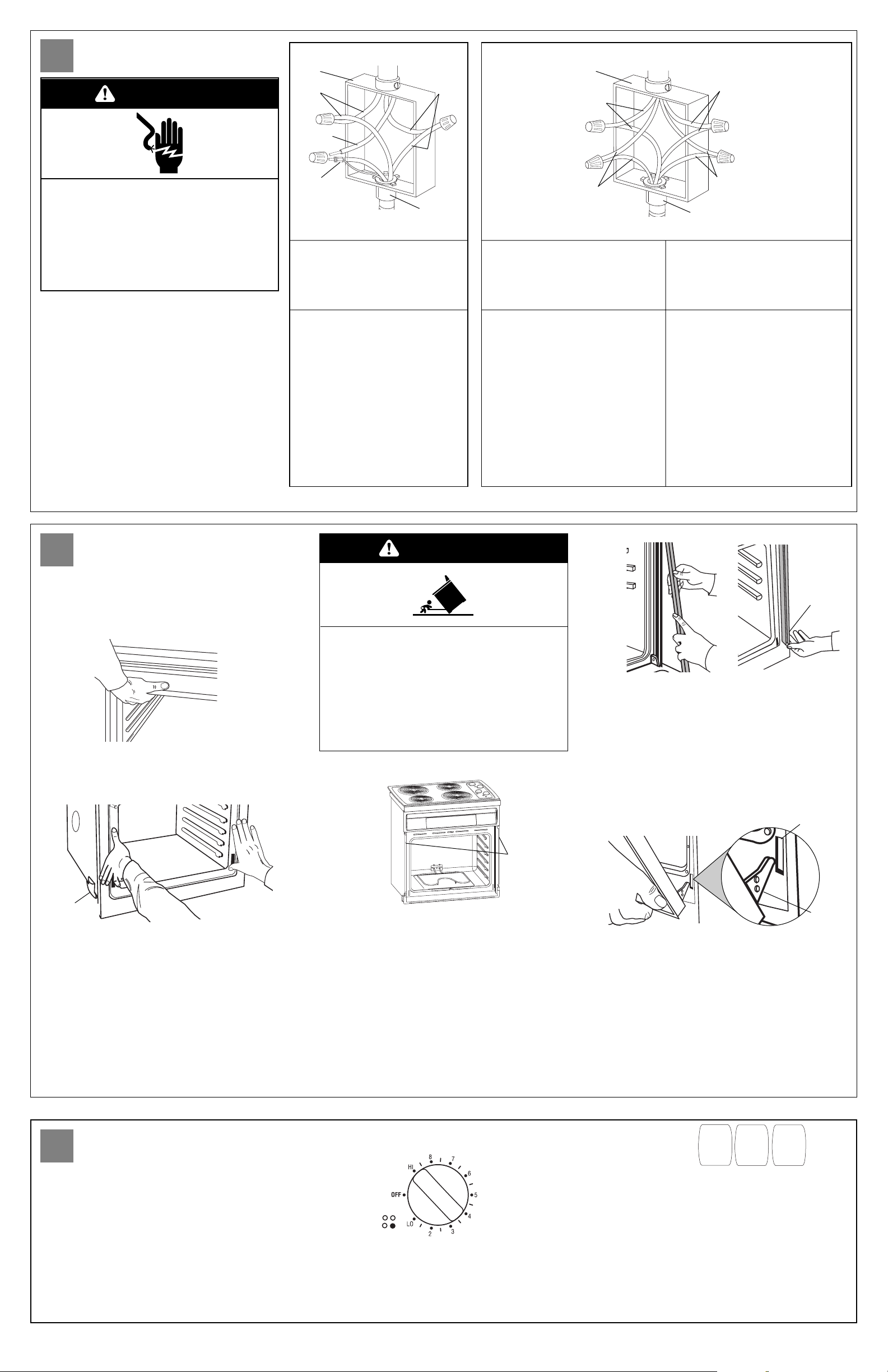
4. Make electrical connection following the
steps needed for your installation.
1. Disconnect the power supply.
2. Remove the junction box cover.
3. Connect range cable to junction box through
the U.L.-listed conduit connector.
4. Connect the two black wires together with
twist-on connectors.
5. Connect the two red wires together with
twist-on connectors.
6. Complete electrical connection according to
local codes and ordinances.
Figure 1
junction
box
red
wires
white
wire
white and bare
ground range
cable wires —
factory crimped
cable from
power supply
black
wires
cable from
range
U.L.-listed
conduit
connector
Figure 2
cable from
power supply
cable from
range
junction
box
U.L.-listed
conduit connector
red
wires
white
wires
black wires
bare ground
wires
If local codes PERMIT
connecting cabinet-ground
conductor to neutral white
wire in junction box:
If local codes DO NOT PERMIT
connecting cabinet-ground
conductor to neutral white
wire in junction box:
If connecting to a
four-wire electrical system:
7. Connect the factory-crimped
bare and white range cable
wires to the neutral (white) wire
in junction box. See Figure 1.
8. Replace junction box cover.
7. Separate the factory-crimped
bare and white range cable
wires.
8. Connect white range cable wire
to neutral (white) wire in
junction box. See Figure 2.
9. Connect the bare ground range
cable wire to a grounded wire in
the junction box. See Figure 2.
10. Replace junction box cover.
7. Separate factory-crimped bare
and white range cable wires.
8. Connect white range cable wire
to neutral (white) wire in
junction box. See Figure 2.
9. Connect the bare ground range
cable wire to the green ground
wire in junction box. Do Not
connect bare ground wire to
neutral (white) wire in junction
box. See Figure 2.
10. Replace junction box cover.
Carefully push against seal area of range front
frame when pushing range into cabinet.
Do Not push against outside edges.
Page 3
10.Turn on power supply. The display
panel will light up briefly. “PF” should appear in
the temperature display.
Electrical connection
B
Attachment
C
Check operation
D
5. Lift range into cabinet cutout using the
oven opening as an area to grip. Be careful not to
damage countertop.
To avoid damaging the countertop, lift range
slightly while pushing against seal area of front
frame. Push range into cabinet cutout until
shipping feet almost contact cabinet. Use a
Phillips screwdriver to remove screws attaching
shipping feet. Remove and discard shipping
feet.
Push range completely into cabinet and center
range in cabinet cutout. Be careful not to
damage countertop.
Push trim
into place.
Replace
trim screw.
oven frame
hinge slot
2 screws
Slide top
of trim up.
9. Replace the oven door by inserting ends
of hinges into hinge slots in range frame. Push
behind each hinge so that hinges are pushed into
range frame as far as they will go. Open door and
remove both door removal pins. Close and open
door to check that door closes and opens
completely. If door does not close or open
completely, you have not pushed hinges
completely into frame. Repeat door removal step
and reinsert door into hinge slots again.
shipping
foot
door
hinge
6. Important: Securely fasten range to cabinet
using the two screws provided. Insert the screws
through holes in mounting rails. Do Not
overtighten screws.
7. Slide top end of each trim upward onto
range side rails. Push each trim into place at
bottom of trim. Use screws to attach each trim to
range. Take care not to scratch other surfaces with
ends of trim.
11. Check the operation of the cooktop
elements. Push in and turn each surface unit
control knob to “HI” position. Check the operation
of the cooktop elements and indicator lights.
8. Replace oven racks.
12.Check the operation of the oven
element. Press the “BROIL” pad. “BROIL” will
appear in the display. Press the “START” pad.
Make sure the oven door is closed and the “ON”
light is shown in the display area. After 2
minutes, partially open oven door. You should
feel heat from the oven. Press the “CANCEL” pad.
If your oven does not heat or an “F”, followed by
a number, appears in the display, contact your
dealer or check the “If you need service...”
section of this Installation Instructions.
BAKE
BROIL
CLEAN
Electrical Shock Hazard
Turn power supply off before connecting
wires.
Use 8-gauge solid copper wire.
Electrically ground range.
Failure to follow these instructions can result
in death, fire, or electrical shock.
Tip Over Hazard
A child or adult can tip the range and be killed.
Securely attach mounting screws to cabinet.
Reattach mounting screws if the range is
moved.
Failure to follow these instructions can result
in death or serious burns to children and
adults.
WARNING
WARNING
Page 5

If range does not operate:
嘼 Check that circuit breaker is not tripped or
house fuse blown.
嘼 See Use and Care Guide for troubleshooting list.
Printed in U.S.A.
If you need service:
Maintain the quality built into your range by calling
an authorized service company.
To obtain the name and number of an authorized
service company:
嘼 Contact the dealer from whom you purchased
your range; or
嘼 Look in the Yellow Pages of your telephone
directory under “Appliances — Household —
Major — Service and Repair” for an authorized
service company; or
嘼 Call the Consumer Assistance Center. The toll-
free phone number is listed in your Use and
Care Guide.
When you call, you will need:
嘼 The range model number.
嘼 The range serial number.
Both numbers are listed on the model/serial rating
plate, located on the oven door or on the oven
frame.
If you need assistance:
If you have questions about operating, cleaning or
maintaining your range:
嘼 Refer to your Use and Care Guide.
嘼 Call the Consumer Assistance Center: Check
your Use and Care Guide for a toll-free
number to call or call the dealer from whom
you purchased this appliance. The dealer is
listed in the Yellow Pages of your phone
directory under “Appliances — Household —
Major — Service and Repair.”
NOTE:
Refer to Use and Care Guide for operating
instructions and cleaning instructions.
Part No. 3191799 Rev. A
© 1999 Whirlpool Corporation
 Loading...