

Whirlpool 29-718, 35-718 User Manual
IMPORTANT:
Read and save
these instructions.
IMPORTANT:
Installer: Leave Installation Instructions
with homeowner.
Homeowner: Keep Installation Instructions
for future reference.
Save Installation Instructions for electrical
inspector’s use.
30” and 36” Convertible
Range Hood
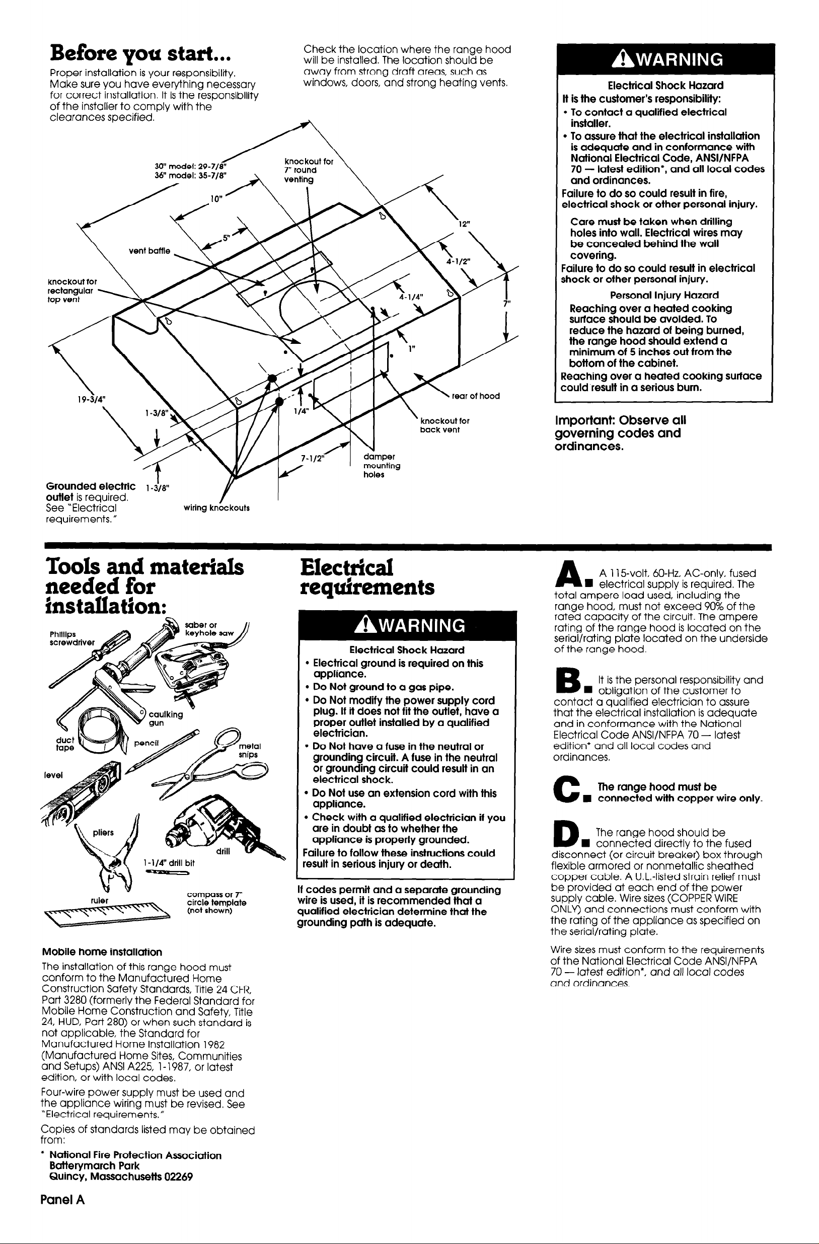
Before you start...
Proper installation is your responsibility.
Make sure you have everything necessary
for correct installation. It is the responsibility
of the installer to comply with the
clearances specified.
30” model: 29-718
36’ model: 35-718”
knockout for
Check the location where the range hood
will be installed. The location should be
away from strong draft areas, such as
windows, doors, and strong heating vents.
rear of hood
Electrical Shock Hazard
It is the customer’s responsibility:
l
To contact a qualified electrical
installer.
l
To assure that the electrical installation
is adequate and in conformance with
National Electrical Code, ANSVNFPA
70 - latest edition*, and all local codes
and ordinances.
Failure to do so could result in fire,
electrical shock or other personal injury.
Care must be taken when drilling
holes into wall. Electrical wires may
be concealed behind the wall
covering.
Failure to do so could result in electrical
shock or other personal injury.
Personal Injury Hazard
Reaching over a heated cooking
surface should be avoided. To
reduce the hazard of being burned,
the range hood should extend a
minimum of 5 inches out from the
bottom of the cabinet.
Reaching over a heated cooking surface
zould result in a serious burn.
Grounded electric 1 -&w
outlet is required.
See “Electrical
requirements, fl
wiring knockouts
Tools and materials
needed for
installation:
compass or 7”
circle template
(not shown)
\
knockout for
back vent
mounting
holes
Electrical requirements
Electrical Shock Hazard
l
Electrical ground is required on this
appliance.
l
Do Not ground to a gas pipe.
l
Do Not modify the power supply cord
plug. If it does not fit the outlet, have a
proper outlet installed by a qualified
electrician.
l
Do Not have a fuse in the neutral or
grounding circuit. A fuse in the neutral
or grounding circuit could result in an
electrical shock.
l
Do Not use an extension cord with this
appliance.
l
Check with a qualified electrician if you
are in doubt as to whether the
appliance is properly grounded.
Failure to follow these instructions could
result in serious injury or death.
If codes permit and a separate grounding
wire is used, it is recommended that a
qualified electrician determine thal the
grounding path is adequate.
Important: Observe all
governing codes and
ordinances.
A 115-volt, 60-Hz, AC-only, fused
A
n electrical supplv is reauired. The
total ampere load used’including the
range hood, must not exceed 90% of the
rated capacity of the circuit. The ampere
rating of the range hood is located on the
serial/rating plate located on the underside
of the range hood.
B
contact a qualified electrician to assure
that the electrical installation is adequate
and in conformance with the National
Electrical Code ANSI/NFPA 70 - latest
edition* and all local codes and
ordinances,
C
D
disconnect (or circuit breaker) box through
flexible armored or nonmetallic sheathed
copper cable. A U.L.-listed strain relief must
be provided at each end of the power
supply cable. Wire sizes (COPPER WIRE
ONLY) and connections must conform with
the rating of the appliance as specified on
the serial/rating plate.
It is the personal responsibility and
n obliaation of the customer to
The range hood must be
n connected with copper wire only.
The range hood should be
n connected directly to the fused
Mobile home installation
The installation of this range hood must
conform to the Manufactured Home
Construction Safety Standards, Title 24 CFR,
Part 3280 (formerly the Federal Standard for
Mobile Home Construction and Safety, Title
24, HUD, Part 280) or when such standard is
not applicable, the Standard for
Manufactured Home Installation 1982
(Manufactured Home Sites, Communities
and Setups) ANSI A225, 1 - 1987, or latest
edition, or with local codes.
Four-wire power supply must be used and
the appliance wiring must be revised. See
“Electrical requirements.”
Copies of standards listed may be obtained
from:
* National Fire Protection Association
Batterymarch Park
Quincy, Massachusetts 02269
Panel A
Wire sizes must conform to the requirements
of the National Electrical Code ANSI/NFPA
70 - latest edition*, and all local codes
and ordinances.
Venting
requirements
Now start...
With range hood in kitchen.
round ductwork
Fire Hazard
l
Terminate venting system to outside.
. Do Not terminate the vent in an atlic or
other enclosed space.
Failure to follow these instructions could
result in a fire.
Ductwork needed for installation is not
included. If roof or wall cap has a damper,
Do Not use damper supplied with hood.
Determine which outside venting method
needs to be used. NOTE: If a non-vented
(recirculating) installation is desired, follow
instructions on Panel D.
The length of the ductwork and number of
elbows should be kept to a minimum to
provide efficient performance. The size of
the ductwork should be uniform. Do Not
install two elbows together. Use duct tape
to seal all joints in the ductwork system.
Ductwork can terminate either through the
roof or wall. Use caulking to seal exterior
wall or roof opening around exhaust hood.
For the most efficient and quiet operation, it
is recommended that the range be vented
vertically through the roof through 7” round
ductwork.
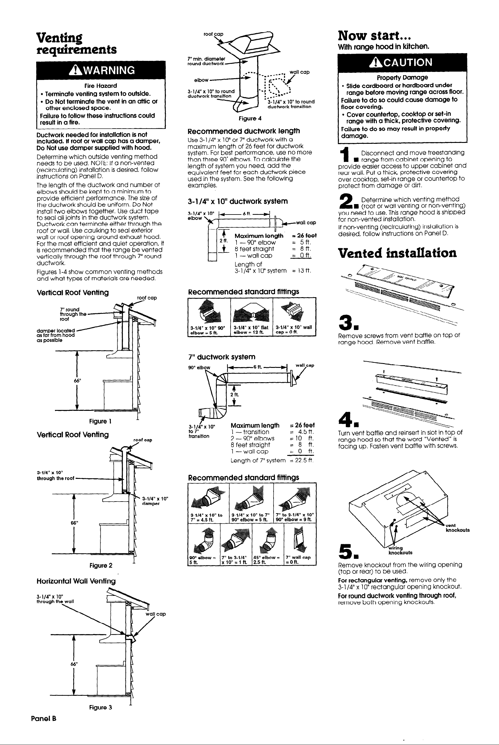
Figures l-4 show common venting methods
and what types of materials are needed.
elbow
3-l/4” x 10” to round
ductwork transition
Figure 4
Recommended ductwork length
Use 3- l/4” x lo” or 7” ductwork with a
maximum length of 26 feet for ductwork
system. For best performance, use no more
than three 90” elbows. To calculate the
length of system you need, add the
equivalent feet for each ductwork piece
used in the system. See the following
examples.
3- l/4” x lo” ductwork system
+- 6 ft. 4
I lb--
I
Length of
3-1/4”xl0”system = 13ft
wall cap
Property Damage
l
Slide cardboard or hardboard under
range before moving range across floor.
Failure to do so could cause damage to
floor covering.
l
Cover countertop, cooktop or set-in
range with a thick, protective covering.
Failure to do so may result in property
damage.
Disconnect and move freestanding
n range from cabinet opening to
1
provide easier access to upper cabinet and
rear wall. Put a thick protective covering
over cooktop, set-in range or countertop to
protect from damage or dirt.
Determine which venting method
I (roof or wall venting or non-venting)
2
you need to use. This range hood is shipped
for non-vented installation.
If non-venting (recirculating) installation is
desired, follow instructions on Panel D.
Vented installation
Vertical Roof Venting
7” round
through the
roof -
damper located
as far from hood
as possible
Figure 1
Vertical Roof Venting
roof coo
1
roof cap
Recommended standard fittings
-
3-114” x IQ” 90”
elbow = 5 ft.
I
3-l/4” x IO” flat
elbow = 12 ft.
7” ductwork system
3-l/Lx lo”
to 7”
transition
Maximum length
1 - transition
2 - 90” elbows
8 feet straight
l-
wall cap
Length of 7” system = 22.5 ft.
3-114” x 10” wall
cap=oft.
I
= 26 feet
= 4.5ft.
=lO ft.
= 8 ft.
= 0 ft.
I
Remove screws from vent baffle on top of
range hood. Remove vent baffle.
-
4.
Turn vent baffle and reinsert in slot in top of
range hood so that the word “Vented” is
facing up, Fasten vent baffle with screws.
3-114” x 10”
through the roof
Figure 2
Horizontal Wall Venting
1
Recommended standard fittings
lo”
knockouts
knockouts
Remove knockout from the wiring opening
(top or rear) to be used.
For rectangular venting, remove only the
3-l /4” x 10” rectangular opening knockout.
For round ductwork venting through roof,
remove both opening knockouts.
Panel B
Figure 3 ’
 Loading...