

Whirlpool 285595 Instruction Sheet
INSTALLATION INSTRUCTIONS
for 285595 Neutral Pack (50 Hz)
wWARNING
Electrical Shock Hazard
Disconnect power before servicing.
Replace all panels before operating.
Failure to do so can result in death or electrical shock.
NOTE: The neutral drain pack cannot be used in direct-into-spin gearcases.
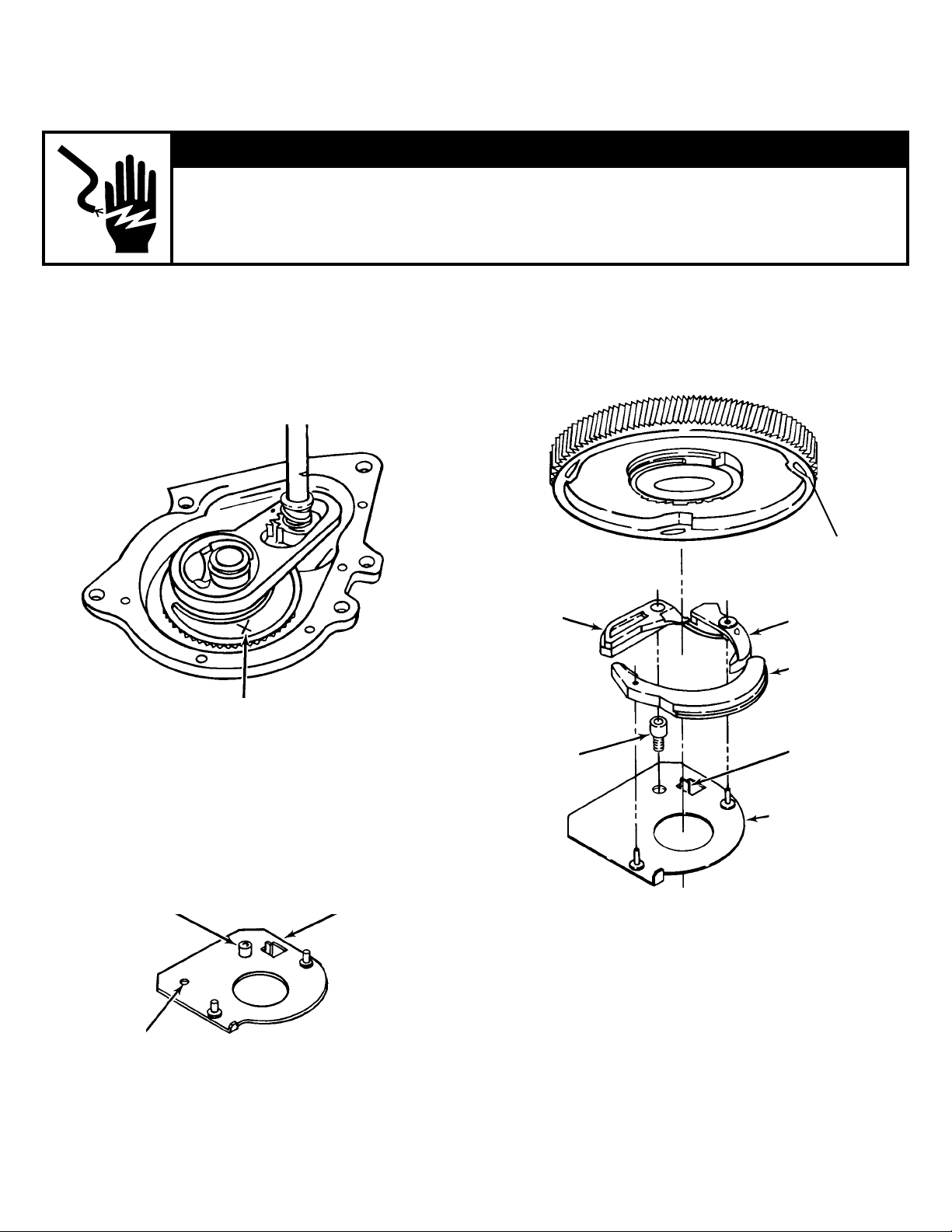
Retainer Rack-Shoulder Pawl
Stud Determination Procedure
1. Examine the main drive gear to see if an “X” is
marked into it. See Figure 1.
Location of “X”
mark on the main
drive gear
Figure 1
3. If the answer to number 1 is no, then use old rack
retainer and small pawl stud with yellow or orange
paint dot. Refer to Figure 3, Rack Retainer.
Spin gear assembly
(Includes: 62570 Spin
gear, 63343 Strike cam,
63342 Delay spring)
Spin
pawl
Shoulder
pawl
stud
Trip lever
Latch
Tab
2. If the answer to number 1 is yes, then use new rack
retainer and large pawl stud with blue paint dot. See
Figure 2.
Large pawl
stud with blue
Loctite patch
ID hole
Figure 2
© Whirlpool Corporation 1999
(All Rights Reserved)
New rack
retainer
Retainer rack
(Old shown)
Figure 3
4. After determining which rack retainer and pawl stud
should be used, follow installation procedure.
1
Instruction Sheet 285683 Rev. A 1/99
(continued)

Installation Procedure
1. Remove from gearcase: Spin gear, delay spring and
strike cam. Dispose of these components and replace
with spin gear assembly. (See Figure 3, Spin Gear
Assembly.)
2. Install rack retainer using the shoulder pawl stud.
(Use rack-stud determination procedure to find out
which rack retainer and pawl stud should be used.)
3. Install trip lever. The spring of the trip lever MUST rest
against the tab on the rack retainer, and trip lever will
snap into place.
4. Install spin pawl and latch as shown.
285683-A
2
 Loading...